

Page 1

Thermal Design Guide for
Socket F (1207) Processors
32800Publication # 3.00Revision:
August 2006Issue Date:
Advanced Micro Devices
Page 2

© 2005 Advanced Micro Devices, Inc. All rights reserved.
The contents of this document are provided in connection with Advanced Micro Devices,
Inc. (“AMD”) products. AMD makes no representations or warranties with respect to the
accuracy or completeness of the contents of this publication and reserves the right to make
changes to specifications and product descriptions at any time without notice. The information contained herein may be of a preliminary or advance nature and is subject to change
without notice. No license, whether express, implied, arising by estoppel or otherwise, to
any intellectual property rights is granted by this publication. Except as set forth in AMD’s
Standard Terms and Conditions of Sale, AMD assumes no liability whatsoever, and disclaims any express or implied warranty, relating to its products including, but not limited
to, the implied warranty of merchantability, fitness for a particular purpose, or infringement
of any intellectual property right.
AMD’s products are not designed, intended, authorized or warranted for use as components in systems intended for surgical implant into the body, or in other applications
intended to support or sustain life, or in any other application in which the failure of
AMD’s product could create a situation where personal injury, death, or severe property or
environmental damage may occur. AMD reserves the right to discontinue or make changes
to its products at any time without notice.
Trademarks
AMD, the AMD Arrow logo, and combinat ions ther eo f, are trad em arks of Adva nced Mic ro Devi ces , Inc .
Other product names used in this publication are for identification purposes only and may be trademarks of their respective companies.
Page 3

32800 Rev. 3.00 August 2006
Thermal Design Guide for Socket F (1207) Processors
Contents
Revision History . . . . . . . . . . . . . . . . . . . . . . . . . . . . . . . . . . . . . . . . . . . . . . . . . . . . . . . . . . . . . . . . .9
Chapter 1 Introduction . . . . . . . . . . . . . . . . . . . . . . . . . . . . . . . . . . . . . . . . . . . . . . . . . . . . . . . .11
1.1 Summary of Requirements . . . . . . . . . . . . . . . . . . . . . . . . . . . . . . . . . . . . . . . . . . . . .11
Chapter 2 Processor Thermal Solutions . . . . . . . . . . . . . . . . . . . . . . . . . . . . . . . . . . . . . . . . . .13
2.1 Processor Specifications . . . . . . . . . . . . . . . . . . . . . . . . . . . . . . . . . . . . . . . . . . . . . . .13
2.2 Socket Description . . . . . . . . . . . . . . . . . . . . . . . . . . . . . . . . . . . . . . . . . . . . . . . . . . .14
Chapter 3 Thermal Design of Platforms Using the AMD Processor-In-a-Box (PIB)
Thermal Solution . . . . . . . . . . . . . . . . . . . . . . . . . . . . . . . . . . . . . . . . . . . . . . . . . . .15
3.1 Motherboard Component Height Restrictions . . . . . . . . . . . . . . . . . . . . . . . . . . . . . .15
3.2 Thermal Solution Design Requirements . . . . . . . . . . . . . . . . . . . . . . . . . . . . . . . . . . .16
3.3 Sample Heat Sinks and Attachment Methods . . . . . . . . . . . . . . . . . . . . . . . . . . . . . . .16
3.3.1 Backplate Assembly . . . . . . . . . . . . . . . . . . . . . . . . . . . . . . . . . . . . . . . . . . . .18
3.3.2 Retention Frame . . . . . . . . . . . . . . . . . . . . . . . . . . . . . . . . . . . . . . . . . . . . . . .19
Chapter 4 Thermal Design of Custom 1U-2P Systems . . . . . . . . . . . . . . . . . . . . . . . . . . . . . .21
4.1 Motherboard Component Height Restrictions . . . . . . . . . . . . . . . . . . . . . . . . . . . . . .21
4.2 Thermal Solution Design Requirements . . . . . . . . . . . . . . . . . . . . . . . . . . . . . . . . . . .22
4.3 Sample Heat Sinks and Attachment Methods . . . . . . . . . . . . . . . . . . . . . . . . . . . . . . .22
4.3.1 Backplate Assembly . . . . . . . . . . . . . . . . . . . . . . . . . . . . . . . . . . . . . . . . . . . .24
4.3.2 Spring Screws . . . . . . . . . . . . . . . . . . . . . . . . . . . . . . . . . . . . . . . . . . . . . . . . .24
4.3.3 Heat Sink . . . . . . . . . . . . . . . . . . . . . . . . . . . . . . . . . . . . . . . . . . . . . . . . . . . . .25
4.3.4 Fans . . . . . . . . . . . . . . . . . . . . . . . . . . . . . . . . . . . . . . . . . . . . . . . . . . . . . . . . .26
4.3.5 Thermal Interface Material . . . . . . . . . . . . . . . . . . . . . . . . . . . . . . . . . . . . . . .27
Chapter 5 Thermal Design of Custom 2U-4P Systems . . . . . . . . . . . . . . . . . . . . . . . . . . . . . .29
5.1 Motherboard Component Height Restrictions . . . . . . . . . . . . . . . . . . . . . . . . . . . . . .29
5.2 Thermal Solution Design Requirements . . . . . . . . . . . . . . . . . . . . . . . . . . . . . . . . . . .30
5.3 Sample Heat Sinks and Attachment Methods . . . . . . . . . . . . . . . . . . . . . . . . . . . . . . .30
5.3.1 Backplate Assembly . . . . . . . . . . . . . . . . . . . . . . . . . . . . . . . . . . . . . . . . . . . .32
5.3.2 Spring Clip . . . . . . . . . . . . . . . . . . . . . . . . . . . . . . . . . . . . . . . . . . . . . . . . . . .33
5.3.3 Retention Frame . . . . . . . . . . . . . . . . . . . . . . . . . . . . . . . . . . . . . . . . . . . . . . .33
Contents 3
Page 4

Thermal Design Guide for Socket F (1207) Processors
32800 Rev. 3.02 August 2006
5.3.4 Heat Sink . . . . . . . . . . . . . . . . . . . . . . . . . . . . . . . . . . . . . . . . . . . . . . . . . . . . .33
5.3.5 Fans . . . . . . . . . . . . . . . . . . . . . . . . . . . . . . . . . . . . . . . . . . . . . . . . . . . . . . . . .35
5.3.6 Thermal Interface Material . . . . . . . . . . . . . . . . . . . . . . . . . . . . . . . . . . . . . . .35
Appendix A Keep-Out Drawings for Platforms Using the PIB Thermal Solution for
Socket F (1207) Processors . . . . . . . . . . . . . . . . . . . . . . . . . . . . . . . . . . . . . . . . . . . .37
Appendix B Keep-Out Drawings for Custom 1U-2P Systems Based on the
Socket F (1207) Processor . . . . . . . . . . . . . . . . . . . . . . . . . . . . . . . . . . . . . . . . . . . .45
Appendix C Keep-Out Drawings for Custom 2U-4P Systems Based on the
Socket F (1207) Processor . . . . . . . . . . . . . . . . . . . . . . . . . . . . . . . . . . . . . . . . . . . .53
Appendix D Flow Simulation Results for Custom 2U-4P Systems Based on
Socket F (1207) Processors . . . . . . . . . . . . . . . . . . . . . . . . . . . . . . . . . . . . . . . . . . . .61
4 Contents
Page 5

32800 Rev. 3.00 August 2006
Thermal Design Guide for Socket F (1207) Processors
List of Figures
Figure 1. The 1207-Pin Socket. . . . . . . . . . . . . . . . . . . . . . . . . . . . . . . . . . . . . . . . . . . . . . . . . . . .14
Figure 2. Motherboard Component Height Restrictions for Platforms Using the
AMD PIB Thermal Solution. . . . . . . . . . . . . . . . . . . . . . . . . . . . . . . . . . . . . . . . . . . . . .15
Figure 3. Exploded View of Thermal Solution AMD PIB Platforms based on
Socket F (1207) Processors. . . . . . . . . . . . . . . . . . . . . . . . . . . . . . . . . . . . . . . . . . . . . . .18
Figure 4. Motherboard Component Height Restrictions for Custom 1U-2P Systems. . . . . . . . . .21
Figure 5. Exploded View of Thermal Solution for Custom 1U-2P Systems. . . . . . . . . . . . . . . . .24
Figure 6. High Performance Heat Sink for Custom 1U-2P Systems . . . . . . . . . . . . . . . . . . . . . . .25
Figure 7. Thermal Performance Chart of Heat Sink When Used with a Dual-Core Processor
in 90 nm Process. . . . . . . . . . . . . . . . . . . . . . . . . . . . . . . . . . . . . . . . . . . . . . . . . . . . . . .26
Figure 8. Motherboard Component-Height Restrictions for Custom 2U-4P Systems. . . . . . . . . .29
Figure 9. Exploded View of Thermal Solution for Custom 2U-4P System Based on Socket F
(1207) Processors32
Figure 10. High Performance Heat Sink for Custom 2U-4P Systems . . . . . . . . . . . . . . . . . . . . . . .34
Figure 11. Thermal Performance Chart of Heat Sink When Used with a Dual-Core Processor
in 90 nm Process. . . . . . . . . . . . . . . . . . . . . . . . . . . . . . . . . . . . . . . . . . . . . . . . . . . . . . .35
Figure 12. Socket F (1207) PIB Board Component Height Restrictions. . . . . . . . . . . . . . . . . . . . .38
Figure 13. Socket F (1207) PIB Mounting Holes, Contact Pads, and No-Routing Zone . . . . . . . .39
Figure 14. Socket F (1207) PIB Socket Outline and Socket Window. . . . . . . . . . . . . . . . . . . . . . .40
Figure 15. Socket F (1207) PIB Heat Sink Height Restriction Zone. . . . . . . . . . . . . . . . . . . . . . . .41
Figure 16. Socket F (1207) PIB Board No-Through-Hole Keep-Out . . . . . . . . . . . . . . . . . . . . . . .42
Figure 17. Socket F (1207) PIB Board Bottom Side Keep-Out. . . . . . . . . . . . . . . . . . . . . . . . . . . .43
Figure 18. Socket F (1207) 1U-2P Board Component Height Restrictions. . . . . . . . . . . . . . . . . . .46
Figure 19. Socket F (1207) 1U-2P Mounting Holes, Contact Pads, and No-Routing Zone . . . . . .47
Figure 20. Socket F (1207) 1U-2P Socket Outline and Socket Window. . . . . . . . . . . . . . . . . . . . .48
Figure 21. Socket F (1207) 1U-2P Heat Sink Height Restriction Zone. . . . . . . . . . . . . . . . . . . . . .49
Figure 22. Socket F (1207) 1U-2P Board No-Through-Hole Keep-Out . . . . . . . . . . . . . . . . . . . . .50
Figure 23. Socket F (1207) 1U-2P Backplate Contact Zone . . . . . . . . . . . . . . . . . . . . . . . . . . . . . .51
Figure 24. Socket F (1207) 2U-4P Board Component Height Restrictions. . . . . . . . . . . . . . . . . . .54
Figure 25. Socket F (1207) 2U-4P Mounting Holes, Contact Pads, and No-Routing Zone . . . . . .55
List of Figures 5
Page 6

Thermal Design Guide for Socket F (1207) Processors
32800 Rev. 3.02 August 2006
Figure 26. Socket F (1207) 2U-4P Socket Outline and Socket Window. . . . . . . . . . . . . . . . . . . . .56
Figure 27. Socket F (1207) 2U-4P Heat Sink Height Restriction Zone. . . . . . . . . . . . . . . . . . . . . .57
Figure 28. Socket F (1207) 2U-4P Board No-Through-Hole Keep-Out . . . . . . . . . . . . . . . . . . . . .58
Figure 29. Socket F (1207) 2U-4P Backplate Contact Zone . . . . . . . . . . . . . . . . . . . . . . . . . . . . . .59
Figure 30. Floor-Plan of AMD Reference Custom 2U-4P System . . . . . . . . . . . . . . . . . . . . . . . . .61
Figure 31. Streamline Plot of AMD Reference Custom 2U-4P System . . . . . . . . . . . . . . . . . . . . .62
6 List of Figures
Page 7

32800 Rev. 3.00 August 2006
Thermal Design Guide for Socket F (1207) Processors
List of Tables
Table 1. Mechanical and Thermal Specifications for Socket F (1207) Processors. . . . . . . . . . . .13
Table 2. Thermal Solution Design Requirements for Platforms Using Socket F (1207)
PIB processors . . . . . . . . . . . . . . . . . . . . . . . . . . . . . . . . . . . . . . . . . . . . . . . . . . . . . . . .16
Table 3. Components for the Processor Thermal Reference Design for the AMD PIB
Thermal Solution . . . . . . . . . . . . . . . . . . . . . . . . . . . . . . . . . . . . . . . . . . . . . . . . . . . . . .17
Table 4. Thermal Solution Design Requirements for Custom 1U-2P Systems . . . . . . . . . . . . . .22
Table 5. Components for the Processor Thermal Reference Design for Custom
1U-2P Systems . . . . . . . . . . . . . . . . . . . . . . . . . . . . . . . . . . . . . . . . . . . . . . . . . . . . . . . .23
Table 6. Fin Parameters. . . . . . . . . . . . . . . . . . . . . . . . . . . . . . . . . . . . . . . . . . . . . . . . . . . . . . . . .25
Table 7. Thermal Solution Design Requirements for Custom 2U-4P Systems . . . . . . . . . . . . . .30
Table 8. Components for the Processor Thermal Reference Design for Custom
2U-4P Systems . . . . . . . . . . . . . . . . . . . . . . . . . . . . . . . . . . . . . . . . . . . . . . . . . . . . . . . .31
Table 9. Chemical Element of SK7 Spring Steel . . . . . . . . . . . . . . . . . . . . . . . . . . . . . . . . . . . . .33
Table 10. Fin Parameters. . . . . . . . . . . . . . . . . . . . . . . . . . . . . . . . . . . . . . . . . . . . . . . . . . . . . . . . .34
List of Tables 7
Page 8

Thermal Design Guide for Socket F (1207) Processors
32800 Rev. 3.02 August 2006
8 List of Tables
Page 9
32800 Rev. 3.00 August 2006
Revision History
Thermal Design Guide for Socket F (1207) Processors
Date Revision
July 2006 3.00 Initial Public release.
Description
Revision History 9
Page 10

Thermal Design Guide for Socket F (1207) Processors
32800 Rev. 3.02 August 2006
10 Revision History
Page 11

32800 Rev. 3.00 August 2006
Thermal Design Guide for Socket F (1207) Processors
Chapter 1 Introduction
This document specifies performance requirements for the design of thermal and mechanical
solutions for socket F (1207) processors, utilizing AMD 64-bit technology. Detailed drawings,
descriptions, and design targets are provided to help manufacturers, vendors, and engineers meet the
requirements for the socket F (1207) processors.
1.1 Summary of Requirements
To allow optimal reliability of a processor, the thermal and cooling solution dissipates heat from that
processor operating at the thermal design power. This document specifies the required values for the
thermal and mechanical parameters of systems based on socket F (1207) processors.
Chapter 1 Introduction 11
Page 12

Thermal Design Guide for Socket F (1207) Processors
32800 Rev. 3.02 August 2006
12 Introduction Chapter 1
Page 13

32800 Rev. 3.00 August 2006
Thermal Design Guide for Socket F (1207) Processors
Chapter 2 Processor Thermal Solutions
This chapter describes the thermal solutions for systems based on socket F (1207) processors.
2.1 Processor Specifications
The objective of thermal solutions is to maintain the processor temperature within specified limits.
Thermal performance, physical mounting, acoustic noise, mass, reliability, and cost must be
considered during the design of a thermal solution.
Table 1 lists the pertinent processor specifications for a thermal solution design for systems based on
socket F (1207) processors.
Table 1. Mechanical and Thermal Specifications for Socket F (1207) Processors
Symbol Description
T
Case
A
CPU
Form
Factor
Maximum case
temperature
Processor contact
area
Processor form
factor
Maximum
Value
67°C - 72°C Consult the processor data sheet for the
thermal requirements specific to the
processor.
32.5 mm x
32.5 mm
LGA LGA form factor for socket F (1207)
Interfaces with heat sink
processors
Notes
Chapter 2 Processor Thermal Solutions 13
Page 14

Thermal Design Guide for Socket F (1207) Processors
32800 Rev. 3.02 August 2006
2.2 Socket Description
Figure 1 shows a three-dimensional view of the 1207-pin socket used with socket F (1207)
processors. This socket is based on LGA (land-grid array) technology . The LGA socket has 35 pads x
35 pads on a 1.1 mm pitch, with a 3.52 mm wide de-populated BGA (ball grid array) zone in the
center, plus a 0.66 mm offset between the two BGA arrays. A small solder-ball makes the electrical
and mechanical connection to the motherboard at each socket contact.
Figure 1. The 1207-Pin Socket
14 Processor Thermal Solutions Chapter 2
Page 15
32800 Rev. 3.00 August 2006
Thermal Design Guide for Socket F (1207) Processors
Chapter 3 Thermal Design of Platforms Using
the AMD Processor-In-a-Box (PIB)
Thermal Solution
This chapter describes the motherboard component height restrictions, thermal-solution design
requirements, sample heat sinks, and attachment methods for platforms using the AMD Processor-Ina-Box (PIB) thermal solution for socket F (1207) processors.
3.1 Motherboard Component Height Restrictions
The mounting solution for the heat sink calls for a standard motherboard keep-out region and
mounting holes for the processor. Figure 2 shows an overview of the motherboard component height
restrictions for platforms using the PIB thermal solution for socket F (1207) processors.
Figure 2. Motherboard Component Height Restrictions for Platforms Using the AMD PIB
Thermal Solution
Chapter 3 Thermal Design of Platforms Using the AMD Processor-In-a-
Box (PIB) Thermal Solution
15
Page 16

Thermal Design Guide for Socket F (1207) Processors
32800 Rev. 3.02 August 2006
Depending on the system features and layout, more space around the socket may be available for the
thermal solution than is shown in Figure 2 on page 15. This space permits heat sink designs with
better thermal performance.
Appendix A on page 37 shows a complete, detailed set of keep-out drawings for the AMD PIB
thermal solution for socket F (1207).
3.2 Thermal Solution Design Requirements
T able 2 provides the design-target specifications that must be met for the processor to operate reliably
in a typical platform using the AMD PIB thermal solution for socket F (1207) processors.
Table 2. Thermal Solution Design Requirements for Platforms Using Socket F (1207) PIB
processors
Symbol Description Maximum
L Length of heat sink 68 mm
W Width of heat sink 77 mm
H Height of heat sink 60 mm
θ
ca
M
HS
F
clip
T
A
Notes:
1. This is the thermal resistance required for dual-core, 90-nm socket F (1207) processors. The thermal resistance
requirement may vary depending on the product OPN. The user should consult the processor data sheet for the
thermal requirements specific to the part.
2. Heat sinks weighing up to 450 g can be attached to the motherboard. Heat sinks weighing over 450 g should be tied
directly to the chassis for reliable shock and vibration performance.
Case-to-ambient thermal
resistance
Mass of heat sink
Clip force 75 lbs ±15 lbs
Local ambient temperature near
processor
0.26°C/W
450 g to 700 g
38°C
1
2
3.3 Sample Heat Sinks and Attachment Methods
The heat sink, fan, mounting spring clip, and thermal interface material used for the AMD PIB
thermal solution for socket F (1207) processors are the same as the heat sink, fan, mounting spring
clip, and thermal interface material used for systems based on the socket 940 processor.
The backplate and retention frame are different from those used in the socket 940 processor. The
EMC shield implemented in the socket 940-based systems is not recommended for AMD PIB thermal
solutions for socket F (1207) processors.
16 Thermal Design of Platforms Using the AMD Processor-In-a-
Chapter 3
Box (PIB) Thermal Solution
Page 17

32800 Rev. 3.00 August 2006
Thermal Design Guide for Socket F (1207) Processors
Table 3 lists the parts used in the thermal reference design for the AMD PIB thermal solution for
socket F (1207) processors.
Table 3. Components for the Processor Thermal Reference Design for the AMD PIB
Thermal Solution
Part Description Material Quantity
Heat sink Copper with aluminum fins 1
Heatpipe Sintered-powder copper 2
Fan Plastic 1
Spring clip SK7 heat treated spring steel 1
Retention frame Lexan, 20% glass-filled 2
Backplate Low-carbon steel, anti-corrosive
finish
Insulator Formex GK-17 1
1
Figure 3 on page 18 shows an exploded view of the thermal solution for platforms using an AMD PIB
based on socket F (1207) processors.
Chapter 3 Thermal Design of Platforms Using the AMD Processor-In-a-
Box (PIB) Thermal Solution
17
Page 18

Thermal Design Guide for Socket F (1207) Processors
32800 Rev. 3.02 August 2006
Figure 3. Exploded View of Thermal Solution AMD PIB Platforms based on Socket F (1207)
Processors
3.3.1 Backplate Assembly
The backplate is mounted on the backside of the motherboard and enhances local stiffness to support
shock and vibration loads acting on the heat sink. The backplate assembly prevents excessive
motherboard warpage in the area near the processor. Without a backplate, excessive warpage could
cause serious damage to electrical connections of the processor socket and integrated circuit packages
surrounding the processor. The backplate also serves as a stiffener plate for the LGA socket.
The reference backplate is made from a 1/16-inch, hard-milled steel, has an overall thickness of 0.138
inch (3.5 mm), including stiffening ribs, and has a mounting-hole pitch of 3.5 inches. To
accommodate the capacitors on the backside of the board, there is a square hole in the center of the
backplate.
18 Thermal Design of Platforms Using the AMD Processor-In-a-
Box (PIB) Thermal Solution
Chapter 3
Page 19

32800 Rev. 3.00 August 2006
Thermal Design Guide for Socket F (1207) Processors
Note: Do not cut entirely through the center rib. Doing so will compromise the stiffness of the
backplate.
The plate uses two PennEngineering (PEM) standoffs that serve multiple purposes. The PEM
standoffs serve as attachment points for the retention frame screws. They also align the backplate
properly to the motherboard. Features in the retention frame slide over the standoffs and allow the
installation of the screws with a minimum chance of cross threading. Additionally, four M3.5 PEM
standoffs in the backplate serve as attachment points for the socket.
The insulator prevents the backplate from electrically shorting to the motherboard. A pressuresensitive adhesive in the insulator keeps the backplate in place against the motherboard during
assembly. The insulator also is thick enough to prevent any significant capacitive coupling between
the motherboard and backplate.
3.3.2 Retention Frame
The plastic retention frame, made of 20% glass-filled Lexan, is a two-piece implementation rather
than the single-piece frame used for socket 940. This change accommodates the larger foot-print of
socket F (1207) processors.
The retention frame serves multiple purposes. The retention frame aligns the heat sink and provides a
stop for the heat sink in large shock-force events. The retention frame and backplate are attached to
the motherboard by the motherboard vendor. Two screws securely hold the backplate and retention
frame together. The two mounting tabs on the retention frame serve as attachment points for the heat
sink spring clip.
Chapter 3 Thermal Design of Platforms Using the AMD Processor-In-a-
Box (PIB) Thermal Solution
19
Page 20

Thermal Design Guide for Socket F (1207) Processors
32800 Rev. 3.02 August 2006
20 Thermal Design of Platforms Using the AMD Processor-In-a-
Box (PIB) Thermal Solution
Chapter 3
Page 21

32800 Rev. 3.02 3.0 0 August 2006
Thermal Design Guide for Socket F (1207) Processors
Chapter 4 Thermal Design of Custom 1U-2P
Systems
This chapter describes the motherboard component-height restrictions, thermal-solution design
requirements, sample heat sinks, and attachment methods for custom 1U-2P systems based on socket
F (1207) processors.
Note: These keep-outs are defined for custom rack mount equipment to optimize thermal and
acoustic performance in these systems. These keep-outs are not compliant with AMD
Processor-In-a-Box (PIB) thermal solutions.
4.1 Motherboard Component Height Restrictions
The mounting solution for the heat sink calls for a standard motherboard keep-out region and
mounting holes for the processor. Figure 4 shows an overview of the motherboard component height
restrictions for custom 1U-2P systems based on the thermal solution for socket F (1207) processors.
Figure 4. Motherboard Component Height Restrictions for Custom 1U-2P Systems
Chapter 4 Thermal Design of Custom 1U-2P Systems 21
Page 22

Thermal Design Guide for Socket F (1207) Processors
32800 Rev. 3.02 August 2006
Depending on the system features and layout, more space around the socket may be available for the
thermal solution than is shown in Figure 4 on page 21. This space permits heat sink designs with
better thermal performance.
Appendix B on page 45 shows a complete, detailed set of keep-out drawings for custom 1U-2P
systems based on socket F (1207) processors.
4.2 Thermal Solution Design Requirements
T o maintain the case temperature of the processor below the maximum specification, certain heat sink
design parameters must be considered. Table 4 provides the design-target specifications that must be
met for socket F (1207) processors to operate reliably.
Table 4. Thermal Solution Design Requirements for Custom 1U-2P Systems
Symbol Description Maximum
L Length of heat sink 87 mm
W Width of heat sink 74 mm
H Height of heat sink 28 mm
θ
ca
M
HS
F
clip
T
A
Notes:
1. This is the thermal resistance required for dual core, 90-nm socket F (1207) processors. The thermal resistance
requirement may vary depending on the product OPN. The user should consult the processor data sheet for the
thermal requirements specific to the part.
2. Heat sinks weighing up to 450 g can be attached to the motherboard. Heat sinks weighing over 450 g should be tied
directly to the chassis for more reliable shock and vibration performance.
3. This chapter describes a heat sink weighing less than or equal to 450 g.
Case-to-ambient thermal
resistance
Mass of heat sink 450 g to 700 g
Clip force 75 lbs ±15 lbs
Local air temperature entering
processor heat sink
0.26°C/W
1, 2, 3
38°C
4.3 Sample Heat Sinks and Attachment Methods
The following sections provide one possible thermal design solution and the specifics on attaching
that solution to the motherboard.
Table 5 on page 23 lists the parts used in the thermal reference design solution for 1U-2P systems
based on socket F (1207) processors.
22 Thermal Design of Custom 1U-2P Systems Chapter 4
Page 23

32800 Rev. 3.02 3.0 0 August 2006
Thermal Design Guide for Socket F (1207) Processors
Table 5. Components for the Processor Thermal Reference Design for Custom 1U-2P
Systems
Part Description Material Quantity
Heat sink Copper base, aluminum fins 1
Fan Plastic 1
Spring screw SK7 heat treated spring steel 2
Backplate Low carbon steel, anti-corrosive
finish
Insulator Formex GK-17 1
1
Figure 5 on page 24 shows an exploded view of the components used in the thermal reference design
solution for custom 1U-2P systems based on socket F (1207) processors.
Chapter 4 Thermal Design of Custom 1U-2P Systems 23
Page 24

Thermal Design Guide for Socket F (1207) Processors
32800 Rev. 3.02 August 2006
Figure 5. Exploded View of Thermal Solution for Custom 1U-2P Systems
The following sections describe the mechanical requirements of the components shown in Figure 5.
4.3.1 Backplate Assembly
For details on the backplate assembly, see section 3.3.1 on page 18.
Note: The backplate for this custom design has a mounting-hole pitch of 4.1 inches.
4.3.2 Spring Screws
The spring screws are designed to apply 75 lbs of force to the heat sink. This force is necessary to
help prevent the heat sink from lifting off the package during shock- or vibration-induced events.
24 Thermal Design of Custom 1U-2P Systems Chapter 4
Page 25

32800 Rev. 3.02 3.0 0 August 2006
Thermal Design Guide for Socket F (1207) Processors
Lifting the heat sink away from the processor can result in damage to the processor contact pads, the
socket contacts, or the socket solder-ball joints. Maintaining the spring force is important for the life
of the processor and the socket and for repeated installations and upgrades of the processor.
4.3.3 Heat Sink
Figure 6 shows a picture of the reference design heat sink for 1U-2P systems. The footprint of the
heat sink is 87 mm x 74 mm. The heat sink weighs 420 g and has aluminum fins soldered to a copper
base. The copper base tapers from a thickness of 6 mm at the center to 1.5 mm at the edges. This
tapering provides optimum heat-spreading performance from the processor to the heat sink while
keeping the heat sink weight within specification. The fin geometry is designed to provide optimized
thermal performance in combination with the fans, as described in Section 4.3.4, on page 26, in a
typical 1U-2P system.
Figure 6. High Performance Heat Sink for Custom 1U-2P Systems
Table 6 shows the parameters of the aluminum fins for the high-performance heat sink shown in
Figure 6.
Table 6. Fin Parameters
Length
87 mm 22 mm 26.5 mm 0.4 mm 1.48
Height (at
Center)
Height (at Edges) Thickness Pitch No. of Fins
50
mm
Chapter 4 Thermal Design of Custom 1U-2P Systems 25
Page 26

Thermal Design Guide for Socket F (1207) Processors
32800 Rev. 3.02 August 2006
Other fan and heat sink combinations may yield adequate thermal performance. The system designer
must ensure that the thermal solution provides required cooling for the processor for the given system
layout and flow characteristics.
Because the processor-mounting surface extends above the surface of the cam box on the socket, the
heat sink bottom can be flat. The heat sink must have a flat surface of at least 40 mm x 40 mm,
centered over the processor.
Figure 7 shows the measured thermal performance vs. flow rate for a slightly shorter version of this
heat sink (3.5" hole pitch vs. 4.1" hole pitch). This data represents the expected performance of this
heat sink on a dual-core socket F (1207) processor. Based on flow tests on the AMD reference 1U-2P
system, the flow through the heat sink is estimated to be approximately 20 cubic feet per minute
(CFM). Figure 7 shows that this corresponds to case-to-ambient thermal resistance of 0.24°C/W. This
case-to-ambient thermal resistance has been confirmed through system thermal tests. The
requirement (see Table 4 on page 22) is 0.26°C/W.
Figure 7. Thermal Performance Chart of Heat Sink When Used with a Dual-Core Processor
in 90 nm Process
4.3.4 Fans
AMD has tested the heat sink described in Section 4.3 on page 22 with a row of five 40 mm x 50 mm
x 56 mm fans (Delta Part number GFB0412EHS) in a typical 1U-2P system. The fan has a 27.3-CFM
maximum flow rate and a 1.63-inches water maximum pressure head. The heat sinks are ducted so
the flow from two fans enters each of the processor heat sinks.
26 Thermal Design of Custom 1U-2P Systems Chapter 4
Page 27

32800 Rev. 3.02 3.0 0 August 2006
Thermal Design Guide for Socket F (1207) Processors
4.3.5 Thermal Interface Material
The heat sink contacts the top surface of the processor package and utilizes the thermal interface
material between the processor lid and the heat sink. AMD recommends using a high performance
grease such as Shin-Etsu 7783D or Dow Corning TC-5022. AMD does not recommend using phase
change materials between the heat sink and the processor. Phase-change materials develop high
adhesion forces between the heat sink and processor when the material is in the solid phase. This
strong adhesive force can cause the processor to stick to the heat sink, making heat sink removal
difficult and damaging the socket solder balls.
Chapter 4 Thermal Design of Custom 1U-2P Systems 27
Page 28

Thermal Design Guide for Socket F (1207) Processors
32800 Rev. 3.02 August 2006
28 Thermal Design of Custom 1U-2P Systems Chapter 4
Page 29

32800 Rev. 3.02 August 2006
Thermal Design Guide for Socket F (1207) Processors
Chapter 5 Thermal Design of Custom 2U-4P
Systems
This chapter describes the motherboard component-height restrictions, thermal-solution design
requirements, sample heat sinks, and attachment methods for custom 2U-4P systems based on socket
F (1207) processors.
Note: These keep-outs are defined for custom rack mount equipment to optimize thermal and
acoustic performance in these systems. These keep-outs are not compliant with AMD
Processor-In-a-Box (PIB) thermal solutions.
5.1 Motherboard Component Height Restrictions
The mounting solution for the heat sink calls for a standard motherboard keep-out region and
mounting holes for the processor. Figure 8 shows an overview of the motherboard component height
restrictions for custom 2U-4P systems based on the thermal solution for socket F (1207) processors.
Figure 8. Motherboard Component-Height Restrictions for Custom 2U-4P Systems
Chapter 5 Thermal Design of Custom 2U-4P Systems 29
Page 30

Thermal Design Guide for Socket F (1207) Processors
32800 Rev. 3.00 August 2006
Depending on the system features and layout, more space around the socket may be available for the
thermal solution than is shown in Figure 8 on page 29. This space permits heat sink designs with
better thermal performance.
Appendix C on page 53 shows a complete, detailed set of keep-out drawings for custom 2U-4P
systems based on socket F (1207) processors.
5.2 Thermal Solution Design Requirements
Table 7 provides the design-target specifications that must be met for socket F (1207) processors to
operate reliably in a typical 2U-4P system based on socket F (1207) processors.
Table 7. Thermal Solution Design Requirements for Custom 2U-4P Systems
Symbol Description Maximum
L Length of heat sink 92 mm
W Width of heat sink 58 mm
H Height of heat sink 40 mm
θ
ca
Case-to-ambient thermal
0.26°C/W
1, 2, 3
resistance
M
F
T
HS
clip
A
Local ambient temperature near
Mass of heat sink 450 g to 700 g
Clip force 75 lbs ±15 lbs
38°C
processor
Notes:
1. This is the thermal resistance required for dual-core, 90-nm socket F (1207) processors. The thermal resistance
requirement may vary depending on the product OPN. The user should consult the processor data sheet for the
thermal requirements specific to the part.
2. Heat sinks weighing up to 450 g can be attached to the motherboard. Heat sinks weighing over 450 g should be tied
directly to the chassis for more reliable shock and vibration performance.
3. This chapter describes a heat sink weighing less than or equal to 450 g. Design examples of solutions up to 700 g are
in development.
5.3 Sample Heat Sinks and Attachment Methods
The following sections provide one possible thermal design solution and the specifics on attaching
that solution to the motherboard.
Table 8 on page 31 lists the parts used in the thermal reference design for Custom 2U-4P systems
based on socket F (1207) processors.
30 Thermal Design of Custom 2U-4P Systems Chapter 5
Page 31

32800 Rev. 3.02 August 2006
Thermal Design Guide for Socket F (1207) Processors
Table 8. Components for the Processor Thermal Reference Design for Custom 2U-4P
Systems
Part Description Material Quantity
Heat sink Aluminum 1
Fan Plastic 1
Spring clip SK7 heat treated spring steel 1
Retention frame Lexan , 20% glass-fi lled 2
Backplate Low carbon steel, anti-corrosive
finish
Insulator Formex GK-17 1
1
Figure 9 on page 32 shows an exploded view of the components used in the thermal reference design
solution for custom 2U-4P systems based on socket F (1207) processors.
Chapter 5 Thermal Design of Custom 2U-4P Systems 31
Page 32

Thermal Design Guide for Socket F (1207) Processors
32800 Rev. 3.00 August 2006
Figure 9. Exploded View of Thermal Solution for Custom 2U-4P System Based on Socket F
(1207) Processors
The following sections describe the mechanical requirements of the components shown in Figure 9.
5.3.1 Backplate Assembly
For details on the backplate assembly, see section 3.3.1 on page 18.
Note: The backplate for this custom design has a mounting-hole pitch of 4.1 inches.
32 Thermal Design of Custom 2U-4P Systems Chapter 5
Page 33

32800 Rev. 3.02 August 2006
Thermal Design Guide for Socket F (1207) Processors
5.3.2 Spring Clip
The spring clip is designed to apply 75 lbs of force to the center of the heat sink. This force is
necessary to help prevent the heat sink from lifting off of the package during shock or vibrationinduced events. Lifting the heat sink away from the processor can result in damage to the processor
contact pads, the socket contacts, or the socket solder-ball joints. Maintaining the spring force is
important for the life of the processor and for repeated installations and upgrades of the processor.
The spring clip material is heat-treatable spring steel, SK7. AMD strongly recommends using SK7 or
an equivalent material for the spring clip. The clip should be plated after heat treatment for cosmetic
and anti-corrosive reasons. Table 9 gives the chemical composition of SK7. The heat treatment used
should bring the ultimate strength of the material to a minimum of 1,300 megapascals (MPa) or 189
kilopounds per square inch (kpsi), and it should bring the yield strength to 940 MPa (or 136 kpsi).
Other materials commonly used for heat sink spring clips have been shown to yield under the high
load of the initial spring-clip deflection and become deformed so that the spring clip can no longer
apply the same load.
Table 9. Chemical Element of SK7 Spring Steel
Element Percentage of the Element
C 0.60-0.70
Si Maximum 0.35
Mn 0.80-0.90
P Maximum 0.030
S Maximum 0.030
Fe Remaining balance
5.3.3 Retention Frame
The plastic retention frame, made of 20% glass-filled Lexan, is a two-piece implementation rather
than the single-piece frame used for socket 940. This change accommodates the larger foot-print of
socket F (1207) processors.
The retention frame serves multiple purposes. The retention frame aligns the heat sink and provides a
stop for the heat sink in large shock-force events. The retention frame and backplate are attached to
the motherboard by the motherboard vendor. Two screws securely hold the backplate and retention
frame together. The two mounting tabs on the retention frame serve as attachment points for the heat
sink spring clip.
5.3.4 Heat Sink
Figure 10 on page 34 shows a picture of the reference design heat sink for 2U-4P systems. The
footprint of the reference design heat sink is 92 mm x 58 mm. The heat sink weighs 378 g and has an
aluminum fin stack soldered to the copper base. The copper base tapers from a thickness of 7 mm at
Chapter 5 Thermal Design of Custom 2U-4P Systems 33
Page 34

Thermal Design Guide for Socket F (1207) Processors
32800 Rev. 3.00 August 2006
the center to 2.5 mm at the edges. The heat sink also has three heat pipes soldered to the base and
connected to the top of the fin stack to improve fin efficiency. This design provides optimum heat
spreading performance from the processor to the heat sink. The fin geometry has been designed to
provide optimized thermal performance in combination with the fans, as described in Section 5.3.5,
on page 35, in a typical 2U-4P system.
Figure 10. High Performance Heat Sink for Custom 2U-4P Systems
Table 10 shows the parameters of the aluminum fins for the high-performance heat sink shown in
Figure 10.
Table 10. Fin Parameters
Length Height (at Center) Height (at Edges) Thickness Pitch No of Fins
92 mm 32.5 mm 37 mm 0.2 mm 1.5 mm 39
Other fan and heat sink combinations may yield adequate thermal performance. The system designer
must ensure that the thermal solution provides required cooling for the processor for the given system
layout and flow characteristics.
Because the processor-mounting surface extends above the surface of the cam box on the socket, the
heat sink bottom can be flat. The heat sink must have a flat surface of at least 40 mm x 40 mm,
centered over the processor.
Figure 11 shows the measured thermal performance vs. flow rate for this heat sink. This data
represents the expected performance of this heat sink on a dual-core socket F (1207) processor. Based
34 Thermal Design of Custom 2U-4P Systems Chapter 5
Page 35

32800 Rev. 3.02 August 2006
Thermal Design Guide for Socket F (1207) Processors
on flow simulations of an AMD reference 2U system, the flow-through of the heat sink is
approximately 18 CFM. Figure 1 1 shows that this flow rate corresponds to a case-to-ambient thermal
resistance of 0.22°C/W. This case-to-ambient thermal resistance exceeds requirements (see Table 7
on page 30).
Figure 11. Thermal Performance Chart of Heat Sink When Used with a Dual-Core Processor
in 90 nm Process
5.3.5 Fans
AMD has conducted simulations of the heat sink described in Section 5.3.4 on page 33 with two 60
mm x 60 mm x 38 mm fans (Delta Part number FFB0812EHE-HS2) in series, that is, back to back.
The fans have a maximum flow rate of 80.2 CFM and a maximum pressure drop of 0.8 inches of
water. The heat sinks are ducted so the flow from the two fans enters the processor heat sinks with
some bypass. The bypass is designed to cool the core VRM.
5.3.6 Thermal Interface Material
The heat sink makes contact with the top surface of the processor package utilizing the thermal
interface material between the processor lid and the heat sink. AMD recommends using a high
performance grease such as Shin-Etsu 7783D or Dow Corning TC-5022. AMD does not recommend
using phase change materials between the heat sink and the processor. Phase-change materials
develop high adhesion forces between the heat sink and processor when the material is in the solid
phase. This strong adhesive force may cause the processor to stick to the heat sink, making heat sink
removal difficult and damaging the socket solder balls.
Chapter 5 Thermal Design of Custom 2U-4P Systems 35
Page 36

Thermal Design Guide for Socket F (1207) Processors
32800 Rev. 3.00 August 2006
36 Thermal Design of Custom 2U-4P Systems Chapter 5
Page 37

32800 Rev. 3.00 August 2006
Thermal Design Guide for Socket F (1207) Processors
Appendix A Keep-Out Drawings for Platforms
Using the PIB Thermal Solution for
Socket F (1207) Processors
Appendix A contains detailed recommended keep-out drawings for processor heat sink and mounting
hardware for platforms using socket F (1207) Processor-In-a-Box (PIB) processors. Depending on the
system features and layout, more space around the processor may be available for the thermal
solution than is shown in these drawings. This space permits the design of heat sinks with better
thermal performance.
Appendix A Keep-Out Drawings for Platforms Using the PIB Thermal
Solution for Socket F (1207) Processors
37
Page 38

Thermal Design Guide for Socket F (1207) Processors
8
7
56 4
3
2
1
D
DE
VORPPAETADNOITPIRCSED.VER
WN5002/80/11esaeleRlaitinI0.2
WN6002/81/1
SNOISIVER
C
.gniwardsi
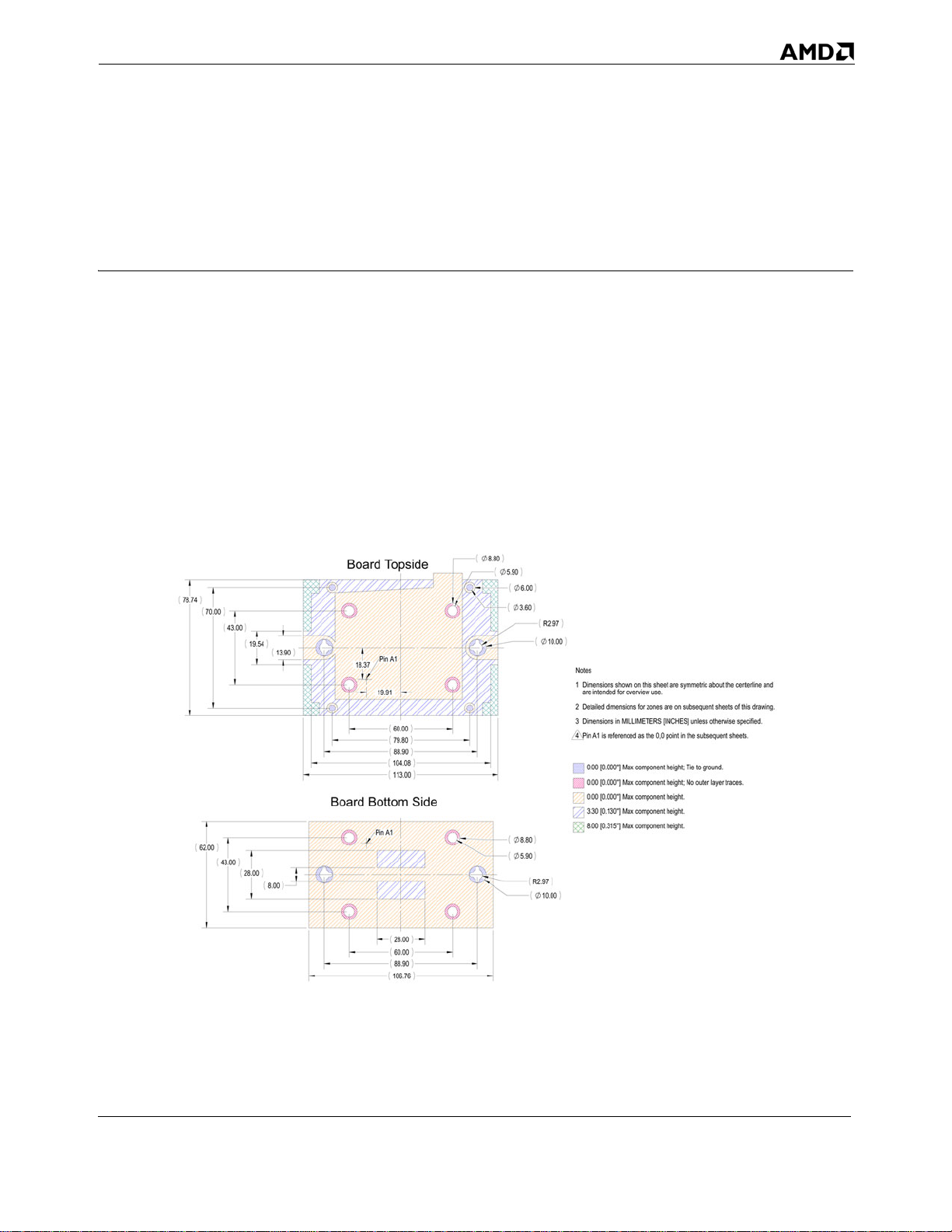
dnaenilretnecehttuobacirtemmyserateehssihtnonwohssnoisnemiD1
.deificepsesiwrehtosselnu]SEHCNI[SRETEMILLIMnisno
.steehstneuqesbusehtnitniop0,0ehtsadecnerefersi1AniP4
htfosteehstneuqesbusnoerasenozrofsnoisnemiddeliateD2
32800 Rev. 3.02 August 2006
B
.secartreyalretuooN;thgiehtnenopmocxaM]''000.0[00.0
.dnuorgoteiT;thgiehtnenopmocxaM]''000.0[00.0
A
6FO1TEEHS
VER
SECIVEDORCIMDECNAVDA
tnenopmoCrossecorP)7021(FtekcoS
SAXET,NITSUA
:ELTIT
1.2
tnailpmoCsnoitcirtseRthgieHdna
1
BIPDMAhtiw
4210000Z97
.ON.GWD
tuopeeK
23
.eltitgniwarddegnahC
1.2
00.6
09.5
08.8
00.01
79.2R
06.3
.esuweivrevorofdednetniera
isnemiD3
setoN
09.88
00.06
1AniP
19.91
73.81
08.97
.thgie
.thgiehtnenopmocxaM]''513.0[00.8
.thgiehtnenopmocxaM]''031.0[03.3
htnenopmocxaM]''000.0[00.0
00.01
79.2R
08.8
09.5
00.311
8
0
.4
01
1AniP
00.06
00.82
4
5
67.601
09.88
6
Board Topside
Board Bottom Side
09.31
45.91
00.34
00.07
47.87
D
Figure 12. Socket F (1207) PIB Board Component Height Restrictions
C
00.26
B
00.8
00.82
00.34
A
38 Keep-Out Drawings for Platforms Using the PIB Thermal
Solution for Socket F (1207) Processors
78
Appendix A
Page 39

32800 Rev. 3.00 August 2006
8
7
56 4
3
2
1
Thermal Design Guide for Socket F (1207) Processors
D
elohgnitnuomdetalp-noN
x352.1940.0
711.079.2R
R
x2ALIATED
1:2ELACS
831.0 x305.3
x2101.2
73.35
B
C
reppocdetaocredloS
241.006.3
632.000.6
x4BLIATED
1:2ELACS
x2054.0
x223.52
x2075.178.93
x273.81327.0
799.0
24.11
A
x2556.0
x231.3
000.0
321.0
36.61
00.0
B
elohgnitnuomdetalp-noN
232.009.5
643.008.8
x4CLIATED
1:2ELACS
3.00876.41
2.53464.36
2.35 5 2x
59.81
49.91
1.96 5 2x
A
6FO2TEEHS
VER
SECIVEDORCIMDECNAVDA
tnenopmoCrossecorP)7021(FtekcoS
SAXET,NITSUA
:ELTIT
1.2
tnailpmoCsnoitcirtseRthgieHdna
1
BIPDMAhtiw
4210000Z97
.ON.GWD
tuopeeK
23
4
5
1AniP
C
o -Ndna,sdaPtcatnoC,seloHgnitnuoM
weiVenoZgnituoR
x259.6R472.0
D
C
0.0000.00
0.39 7 2x10.09
0.787
2x19.99
0.96624.54
1.44136.59
B
6
.secartreyalretuooN;thgiehtnenopmocxaM]''000.0[00.0
.dnuorgoteiT;thgiehtnenopmocxaM]''000.0[00.0
.thgie
78
htnenopmocxaM]''000.0[00.0
A
Figure 13. Socket F (1207) PIB Mounting Holes, Contact Pads, and No-Routing Zone
Appendix A Keep-Out Drawings for Platforms Using the PIB Thermal
Solution for Socket F (1207) Processors
39
Page 40

Thermal Design Guide for Socket F (1207) Processors
8
7
56 4
3
2
1
32800 Rev. 3.02 August 2006
D
634.278.16
189.133.05
001.233.35
C
327.073.81
854.036.11
000.000.0
B
A
6FO3TEEHS
VER
SECIVEDORCIMDECNAVDA
SAXET,NITSUA
tnenopmoCrossecorP)7021(FtekcoS
:ELTIT
1.2
tnailpmoCsnoitcirtseRthgieHdna
1
BIPDMAhtiw
4210000Z97
.ON.GWD
tuopeeK
23
4
1AniP
2.18955.61
38.6 1 1.520
5
19.9 1 0.784
0.0000.00
6
0.72418.39
.dnuorgoteiT;thgiehtnenopmocxaM]''000.0[00.0
wodniWtekcoSdnaeniltuOtekcoS
.thgiehtnenopmocxaM]''000.0[00.0
78
D
C
B
A
Figure 14. Socket F (1207) PIB Socket Outline and Socket Window
40 Keep-Out Drawings for Platforms Using the PIB Thermal
Solution for Socket F (1207) Processors
Appendix A
Page 41

32800 Rev. 3.00 August 2006
8
7
56 4
3
2
1
Thermal Design Guide for Socket F (1207) Processors
D
x247.75372.2
x241.05 479.1
C
801.1 x241.82
x2933.006.8
x2825.004.31
000.000.0
B
A
6FO4TEEHS
VER
SECIVEDORCIMDECNAVDA
tnenopmoCrossecorP)7021(FtekcoS
SAXET,NITSUA
:ELTIT
1.2
tnailpmoCsnoitcirtseRthgieHdna
1
BIPDMAhtiw
4210000Z97
.ON.GWD
tuopeeK
23
x2728.000.12
4
3.00 8 2x76.41
2x71.95
2.833
2.65 4 2x67.41
5
1AniP
0.0000.00
enoZnoitcirtseRthgieHkniStaeH
1.08 6 2x27.59
1.26 5 2x32.13
6
1.44 1 2x36.59
.thgiehtnenopmocxaM]''513.0[00.8
.thgiehtnenopmocxaM]''031.0[03.3
D
C
B
A
78
Figure 15. Socket F (1207) PIB Heat Sink Height Restriction Zone
Appendix A Keep-Out Drawings for Platforms Using the PIB Thermal
Solution for Socket F (1207) Processors
41
Page 42

Thermal Design Guide for Socket F (1207) Processors
8
7
56 4
3
2
1
32800 Rev. 3.02 August 2006
D
C
B
A
6FO5TEEHS
VER
SECIVEDORCIMDECNAVDA
tnenopmoCrossecorP)7021(FtekcoS
SAXET,NITSUA
:ELTIT
1.2
tnailpmoCsnoitcirtseRthgieHdna
1
BIPDMAhtiw
4210000Z97
.ON.GWD
tuopeeK
23
4
449.173.94
794.036.21
000.000.0
5
2.88573.29
6
0.0000.00
1.31833.47
78
stnenopmocelohhguorhtoN
1AniP
No-Through-H ole Com ponents Zone
D
C
B
A
Figure 16. Socket F (1207) PIB Board No-Through-Hole Keep-Out
42 Keep-Out Drawings for Platforms Using the PIB Thermal
Solution for Socket F (1207) Processors
Appendix A
Page 43

32800 Rev. 3.00 August 2006
8
7
56 4
3
2
1
Thermal Design Guide for Socket F (1207) Processors
D
x2321.0
794.036.21
31.3
C
x2075.1
x2327.0
665.073.41
472.173.23
000.000.0
188.0
271.073.4
73.81
73.22
449.173.94
78.93
B
A
6FO6TEEHS
VER
SECIVEDORCIMDECNAVDA
tnenopmoCrossecorP)7021(FtekcoS
SAXET,NITSUA
:ELTIT
1.2
tnailpmoCsnoitcirtseRthgieHdna
1
BIPDMAhtiw
4210000Z97
.ON.GWD
tuopeeK
23
4
2.88573.29
5
2.53464.36
)draoBfoedisrednUmorfweiV(ediSmottoBdraoB
elohurhtdetalp-noN
x408.8643.0
1.96 5 2x
1.33 5 2x33.91
49.91
6
.secartreyalretuooN;thgiehtnenopmocxaM]''000.0[00.0
0.233
5.91
2x
0.00
0.000
0.39 7 2x
10.09
0.96624.54
.dnuorgoteiT;thgiehtnenopmocxaM]''000.0[00.0
.thgie
78
htnenopmocxaM]''000.0[00.0
1.31833.47
elohurhtdetalp-noN
x200.01493.0
D
C
B
A
Figure 17. Socket F (1207) PIB Board Bottom Side Keep-Out
Appendix A Keep-Out Drawings for Platforms Using the PIB Thermal
Solution for Socket F (1207) Processors
43
Page 44

Thermal Design Guide for Socket F (1207) Processors
32800 Rev. 3.02 August 2006
44 Keep-Out Drawings for Platforms Using the PIB Thermal
Solution for Socket F (1207) Processors
Appendix A
Page 45

32800 Rev. 3.00 August 2006
Thermal Design Guide for Socket F (1207) Processors
Appendix B Keep-Out Drawings for Custom 1U-
2P Systems Based on the Socket F
(1207) Processor
Appendix B contains detailed recommended keep-out drawings for processor heat sink and mounting
hardware for a custom 1U-2P system based on the socket F (1207) processors. Depending on the
system features and layout, more space around the processor may be available for the thermal
solution than is shown in these drawings. This space permits the design of heat sinks with better
thermal performance.
Note: These keep-outs are defined for custom rack mount equipment to optimize thermal and
acoustic performance in these systems. These keep-outs are not compliant with AMD
Processor-In-a-Box (PIB) thermal solutions.
Appendix B Keep-Out Drawings for Custom 1U-2P Systems Based on the
Socket F (1207) Processor
45
Page 46

Thermal Design Guide for Socket F (1207) Processors
8
7
56 4
3
2
1
32800 Rev. 3.02 August 2006
SNOISIVER
D
DEVORPPAETADNOITPIRCSED.VER
WN5002/60/21
WN6002/13/10
5002/10
5002/30
xnimm68.0-f
.daCotuAfodaetsniskroWdiloSnituopeekdetaerC
gniwardtuo-peekS2U1)7021(FtekcoSfoesaeleR
otfihsnoigirooteudsegnahcnoisnemiD
P2/U1otnoitatonS2U1degnahC
.
segnahcgnittamroF
ynimm86.0-dna
0.1
1.3
0.2
0.3
.sdap
dezilatemevahdnarenalpocebdluohssenoztcatnocerawrdaH
setoN
1
26.7
C
.deificepsesiwrehtosselnu]SEHCNI[SRETEMILLIMnisnoi
.steehstneuqesbusehtnitniop0,0ehtsadecnerefersi1AniP
.detalptoneraselohgnitnuomerawdrahknistaeH
snemiD
2
3
4
.secartreyalretuooN;thgiehtnenopmocxaM]''000.0[00.0
.dnuorgoteiT;thgiehtnenopmocxaM]''000.0[00.0
.thgie
htnenopmocxaM]''000.0[00.0
B
.thgiehtnenopmocxaM]''787.0[00.02
.thgiehtnenopmocxaM]''031.0[03.3
A
6FO1TEEHS
VER
SECIVEDORCIMDECNAVDA
tnenopmoCrossecorP)7021(FtekcoS
SAXET,NITSUA
:ELTIT
1.3
,snoitcirtseRthgieHdnatuopeeK
rotcaFmroFP2/U1m
otsuCrof
1
8210000Z97
.ON.GWD
23
4
08.8
09.5
5
42.521
09.88
00.06
1AniP
1AniP
00.121
00.82
6
Board To pside
00.31
BoardBottomSide
78
09.31
00.34
00.65
47.87
D
C
00.8
B
00.8
00.82
00.66
A
Figure 18. Socket F (1207) 1U-2P Board Component Height Restrictions
46 Keep-Out Drawings for Custom 1U-2P Systems Based on the
Socket F (1207) Processor
Appendix B
Page 47

32800 Rev. 3.00 August 2006
8
7
56 4
3
2
1
Thermal Design Guide for Socket F (1207) Processors
D
elohgnitnuomdetalp-noN
493.000.01
432.049.5
seloHgnitnuoM
x2ALIATED
1:2ELACS
x305.3
831.0
x305.2890.0
C
241.006.3
003.026.7
sdaPtcatnoCerawdraH
x4BLIATED
1:2ELACS
reppoc
detaocredloS
A
B
C
B
elohgnitnuomdetalp-noN
643.008.8
232.0
09.5
seloHgnitnuoMtekcoS
1:2ELACS
CLIATED
2.83471.98
2.53 4 2x
1.96 5 2x
A
6FO2TEEHS
VER
SECIVEDORCIMDECNAVDA
tnenopmoCrossecorP)7021(FtekcoS
SAXET,NITSUA
:ELTIT
64.36
49.91
1.3
,snoitcirtseRthgieHdnatuopeeK
rotcaFmroFP2/U1m
otsuCrof
1
8210000Z97
.ON.GWD
23
4
5
1AniP
472.059.6R
0.0000.00
0.39 7 2x10.09
o -Ndna,sdaPtcatnoC,seloHgnitnuoM
0.96 6 2x24.54
1.26632.16
.dnuorgoteiT;thgiehtnenopmocxaM]''000.0[00.0
weiVenoZgnituoR
x224.11054.0
x223.52 799.0
x2628.1
x2075.178.93
x2327.073.81
73.64
D
C
x2973.036.9
x231.3
000.0
321.0
00.0
B
A
6
.secartreyalretuooN;thgiehtnenopmocxaM]''000.0[00.0
78
.thgie
htnenopmocxaM]''000.0[00.0
Figure 19. Socket F (1207) 1U-2P Mounting Holes, Contact Pads, and No-Routing Zone
Appendix B Keep-Out Drawings for Custom 1U-2P Systems Based on the
Socket F (1207) Processor
47
Page 48

Thermal Design Guide for Socket F (1207) Processors
8
7
56 4
3
2
1
32800 Rev. 3.02 August 2006
D
C
B
A
6FO3TEEHS
VER
SECIVEDORCIMDECNAVDA
tnenopmoCrossecorP)7021(FtekcoS
SAXET,NITSUA
:ELTIT
1.3
,snoitcirtseRthgieHdnatuopeeK
rotcaFmroFP2/U1m
otsuCrof
1
8210000Z97
.ON.GWD
23
4
1AniP
wodniWtekcoSdnaeniltuOtekcoS
2.18955.61
5
19.9 1 0.784
0.0000.00
6
0.72418.39
.secartreyalretuoon,thgiehtnenopmocxaM]''000.0[00.0
enoZnoitcirtseRthgieH
78
.thgiehtnenopmocxaM]''000.0[00.0
000.000.0
189.133.05
634.278.16
001.233.35
D
C
327.073.81
854.036.11
B
A
Figure 20. Socket F (1207) 1U-2P Socket Outline and Socket Window
48 Keep-Out Drawings for Custom 1U-2P Systems Based on the
Socket F (1207) Processor
Appendix B
Page 49

32800 Rev. 3.00 August 2006
8
7
56 4
3
2
1
Thermal Design Guide for Socket F (1207) Processors
D
C
B
A
6FO4TEEHS
VER
SECIVEDORCIMDECNAVDA
tnenopmoCr
SAXET,NITSUA
ossecorP)7021(FtekcoS
:ELTIT
1.3
,snoitcirtseRthgieHdnatuopeeK
rotcaFmroFP2/U1motsuCrof
1
8210000Z97
.ON.GWD
23
knistaehhguorhtwolfriawollaotsienoZthgieH
4
3.24982.53
2.83 4 2x
71.98
5
1AniP
0.0000.00
6
weiVenoZnoitcirtseRthgieHkniStaeH
1.26 6 2x
32.16
728.000.12
372.247.75
D
C
000.000.0
B
1.68142.71
..thgiehtnenopmocxaM]''787.0[00.02
.thgiehtnenopmocxaM]''031.0[03.3
A
78
Figure 21. Socket F (1207) 1U-2P Heat Sink Height Restriction Zone
Appendix B Keep-Out Drawings for Custom 1U-2P Systems Based on the
Socket F (1207) Processor
49
Page 50

Thermal Design Guide for Socket F (1207) Processors
8
7
56 4
3
2
1
32800 Rev. 3.02 August 2006
D
C
B
A
6FO5TEEHS
VER
SECIVEDORCIMDECNAVDA
tnenopmoCrossecorP)7021(FtekcoS
SAXET,NITSUA
:ELTIT
1.3
,snoitcirtseRthgieHdnatuopeeK
rotcaFmroFP2/U1motsuCrof
1
8210000Z97
.ON.GWD
23
4
3.16680.41
5
1AniP
0.0000.00
675.036.41
220.273.15
000.000.0
1.59840.59
6
78
.stnenopmocelohhguorhtoN
No-Through-Hole Component Zone
D
C
B
A
Figure 22. Socket F (1207) 1U-2P Board No-Through-Hole Keep-Out
50 Keep-Out Drawings for Custom 1U-2P Systems Based on the
Socket F (1207) Processor
Appendix B
Page 51

32800 Rev. 3.00 August 2006
8
7
56 4
3
2
1
Thermal Design Guide for Socket F (1207) Processors
D
C
x2972.0
x2630.029.0
271.073.4
80.7
472.173.23
188.0
665.073.41
73.22
B
x2527.1
x2014.128.53
A
6FO6TEEHS
VER
SECIVEDORCIMDECNAVDA
tnenopmoCr
SAXET,NITSUA
ossecorP)7021(FtekcoS
:ELTIT
1.3
,snoitcirtseRthgieHdnatuopeeK
rotcaFmroFP2/U1motsuCrof
1
8210000Z97
.ON.GWD
23
28.34
elohgnitnuomdetalp-noN
4
08.8 643.0
3.16680.41
2.94 7 2x74.86
2.83471.98
2.43 5 2x61.86
2x49.91 1.965
5
33.9 1 2x1.335
1AniP
5.9 1 2x0.233
0.0000.00
0.39 7 2x10.09
6
0.86 8 2x22.04
1.26632.16
weiVenoZtcatnoCetalpkcaB
675.036.41
D
493.000.01
elohgnitnuomdetalp-noN
x2
000.000.0
321.0
31.3
C
x2075.1
x273.81
220.273.15
327.0
78.93
B
1.38 0 2x35.04
1.59840.59
.secartreyalretuooN;thgiehtnenopmocxaM]''000.0[00.0
.dnuorgoteiT;thgiehtnenopmocxaM]''000.0[00.0
78
.thgiehtnenopmocxaM]''031.0[03.3
.thgie
htnenopmocxaM]''000.0[00.0
A
Figure 23. Socket F (1207) 1U-2P Backplate Contact Zone
Appendix B Keep-Out Drawings for Custom 1U-2P Systems Based on the
Socket F (1207) Processor
51
Page 52

Thermal Design Guide for Socket F (1207) Processors
32800 Rev. 3.02 August 2006
52 Keep-Out Drawings for Custom 1U-2P Systems Based on the
Socket F (1207) Processor
Appendix B
Page 53

32800 Rev. 3.00 August 2006
Thermal Design Guide for Socket F (1207) Processors
Appendix C Keep-Out Drawings for Custom 2U-
4P Systems Based on the Socket F
(1207) Processor
Appendix C contains detailed recommended keep out drawings for processor heat sink and mounting
hardware for a 2U-4P system based on the socket F (1207) processor. Depending on the system
features and layout, more space around the processor may be available for the thermal solution than is
shown in these drawings. This space permits the design of heat sinks with better thermal
performance.
Note: These keep-outs are defined for custom rack mount equipment to optimize thermal and
acoustic performance in these systems. These keep-outs are not compliant with AMD
Processor-In-a-Box (PIB) thermal solutions.
Appendix C Keep-Out Drawings for Custom 2U-4P Systems Based on the
Socket F (1207) Processor
53
Page 54

Thermal Design Guide for Socket F (1207) Processors
8
7
56 4
3
2
1
32800 Rev. 3.02 August 2006
SNOISIVER
D
DEVORPPAETADNOITPIRCSED.VER
WN5002/60/21
WN6002/13/10
5002/10
5002/30
tuo-peekesaercnI.noitallatsniroftuopeekpilcdednapxE
tuo-peekrossecorpS4U2)7021(FtekcoSfoesaeleR
.daCotuAfodaetsniskroWdilo
6teehSnoxnimm2yb
.segnahcgnittamroF
SnituopeekdetaerC
gniward
0.1
0.2
0.3
06.3
.sdapdezilatemevahdnarenalpocebdluohssenoztcatnocerawrdaH
P4/U2otnoitatonS4U2degnahC
setoN
1.3
1
26.7
C
.deificepsesiwreh
.steehstneuqesbuseht
tosselnu]SEHCNI[SRETEMILLIMnisnoisnemiD
.detalptoneraselohgnitnuomerawdrahknistaeH
nitniop0,0ehtsadecnerefersi1AniP
2
3
4
00.01
.secartreyalretuooN;thgiehtnenopmocxaM]''000.0[00.0
.dnuorgoteiT;thgiehtnenopmocxaM]''000.0[00.0
.thgie
htnenopmocxaM]''000.0[00.0
B
.thgiehtnenopmocxaM]''493.0[00.01
.thgiehtne
.thgiehtnenopmocxaM]''031.0[03.3
nopmocxaM]''787.0[00.02
A
6FO1TEEHS
VER
SECIVEDORCIMDECNAVDA
tnenopmoCrossecorP)7021(FtekcoS
SAXET,NITSUA
:ELTIT
1.3
,snoitcirtseRthgieHdnatuopeeK
rotcaFmroFP4/U2motsuCrof
1
9210000Z97
.ON.GWD
23
4
Board Topside
08.8
09.5
5
26.431
41.401
00.57
42.51
00.34
08.05
85.86
D
C
00.06
1AniP
00.31
Board Bottom Side
00.8
B
1AniP
00.82
00.26
A
42.521
09.88
00.121
00.82
6
78
Figure 24. Socket F (1207) 2U-4P Board Component Height Restrictions
54 Keep-Out Drawings for Custom 2U-4P Systems Based on the
Socket F (1207) Processor
Appendix C
Page 55

32800 Rev. 3.00 August 2006
8
7
56 4
3
2
1
Thermal Design Guide for Socket F (1207) Processors
D
elohgnitnuomdetalp-noN
432.049.5
493.000.01
x3890.005.2
seloHgnitnuoMemarF
x2ALIATED
1:2ELACS
x35.3
831.0
C
003.026.7
241.006.3
sdaPtcatnoCerawdraH
x4BLIATED
1:2ELACS
reppoc
detaocredloS
A
B
B
elohgnitnuomdetalp-noN
232.0
643.008.8
09.5
seloHgnitnuoMtekcoS
x4CLIATED
1:2ELACS
3.43487.22
2.97 1 2x75.47
71.9 8 2.834
2.53 4 2x64.36
A
6FO2TEEHS
VER
SECIVEDORCIMDECNAVDA
tnenopmoCr
SAXET,NITSUA
ossecorP)7021(FtekcoS
:ELTIT
1.3
,snoitcirtseRthgieHdnatuopeeK
rotcaFmroFP4/U2motsuCrof
1
9210000Z97
.ON.GWD
23
4
5
C
1AniP
472.059.6R
0.0000.00
o -Ndna,sdaPtcatnoC,seloHgnitnuoM
weiVenoZgnituoR
x2000.000.0
x2324.057.01
x2320.199.52
x2327.177.34
D
x2327.073.81
C
x230.7
772.0
B
1.86647.40
0.96 6 2x
32.1 6 1.266
1.40 4 2x35.65
24.54
.dnuorgoteiT;thgiehtnenopmocxaM]''000.0[00.0
A
6
.secartreyalretuooN;thgiehtnenopmocxaM]''000.0[00.0
78
.thgie
htnenopmocxaM]''000.0[00.0
Figure 25. Socket F (1207) 2U-4P Mounting Holes, Contact Pads, and No-Routing Zone
Appendix C Keep-Out Drawings for Custom 2U-4P Systems Based on the
Socket F (1207) Processor
55
Page 56

Thermal Design Guide for Socket F (1207) Processors
8
7
56 4
3
2
1
32800 Rev. 3.02 August 2006
D
C
B
A
6FO3TEEHS
VER
SECIVEDORCIMDECNAVDA
SAXET,NITSUA
tnenopmoCrossecorP)7021(FtekcoS
:ELTIT
1.3
,snoitcirtseRthgieHdnatuopeeK
rotcaFmroFP4/U2motsuCrof
1
9210000Z97
.ON.GWD
23
4
1
A
niP
2.18955.61
1.52038.61
0.0000.00
0.72418.39
5
19.9 1 0.784
6
.secartreyalretuooN;thgiehtnenopmocxaM]''000.0[00.0
wodniWtekcoSdnaeniltuOtekcoS
enoZnoitcirtseRthgieH
78
000.000.0
634.278.16
370.266.25
189.133.05
D
327.073.81
C
854.036.11
B
.thgiehtnenopmocxaM]''000.0[00.0
A
Figure 26. Socket F (1207) 2U-4P Socket Outline and Socket Window
56 Keep-Out Drawings for Custom 2U-4P Systems Based on the
Socket F (1207) Processor
Appendix C
Page 57

32800 Rev. 3.00 August 2006
8
7
56 4
3
2
1
Thermal Design Guide for Socket F (1207) Processors
D
C
B
A
6FO4TEEHS
VER
SECIVEDORCIMDECNAVDA
SAXET,NITSUA
tnenopmoCr
ossecorP)7021(FtekcoS
:ELTIT
1.3
,snoitcirtseRthgieHdnatuopeeK
rotcaFmroFP4/U2motsuCrof
1
9210000Z97
.ON.GWD
23
rofdengisedsituopeekwolfriasihttahtetoN
.erehtnoeblliwg
tsomehtsipotehT.tekcosehtfoedisrehtienoognacti
dna,deriuqeryltcirtstonsituopeekepiptaeH
.gniwardsihtotlanoziroheratahtsnif
nituorgnituorRDDesuacebeciohclacigol
4
2x3.249
82.53
2.83 4 2x
71.98
2.26057.41
5
1AniP
0.0000.00
6
0.69317.59
weiVenoZnoitcirtseRthgieHkniStaeH
1.266
32.1 6 2 x
x266.25370.2
475.273.56
D
C
000.000.0
726.029.51
B
1.681
2x42.71
.thgiehtnenopmocxaM]''493.0[00.01
.thgiehtnenopmocxaM]''787.0[00.02
.thgiehtnenopmocxaM]''031.0[03.3
A
78
Figure 27. Socket F (1207) 2U-4P Heat Sink Height Restriction Zone
Appendix C Keep-Out Drawings for Custom 2U-4P Systems Based on the
Socket F (1207) Processor
57
Page 58

Thermal Design Guide for Socket F (1207) Processors
8
7
56 4
3
2
1
32800 Rev. 3.02 August 2006
D
C
B
A
6FO5TEEHS
VER
SECIVEDORCIMDECNAVDA
tnenopmoCrossecorP)7021(FtekcoS
SAXET,NITSUA
:ELTIT
1.3
,snoitcirtseRthgieHdnatuopeeK
rotcaFmroFP4/U2motsuCrof
1
9210000Z97
.ON.GWD
23
4
3.16680.41
5
1AniP
0.0000.00
6
794.036.21
449.173.94
000.000.0
1.59840.59
78
iehtnenopmocxaM]''000.0[00.0 .stnenopmocelohhguorhtondnathg
No-Through-H ole Com ponent Zone Vie w
D
C
B
A
Figure 28. Socket F (1207) 2U-4P Board No-Through-Hole Keep-Out
58 Keep-Out Drawings for Custom 2U-4P Systems Based on the
Socket F (1207) Processor
Appendix C
Page 59

32800 Rev. 3.00 August 2006
8
56 4
3
2
Thermal Design Guide for Socket F (1207) Processors
3.16680.41
2.834
B
2.94 7 2x
2.43 5 2x
1.96 5 2x49.91
1.33 5 2x33.91
A
SECIVEDORCIMDECNAVDA
SAXET,NITSUA
tnenopmoCr
,snoitcirtseRthgieHdnatuopeeK
rotcaFmroFP4/U2motsuCrof
ossecorP)7021(FtekcoS
:ELTIT
74.86
71.98
61.86
6FO6TEEHS
VER
1.3
1
9210000Z97
.ON.GWD
23
4
5
D
1
x2972.080.7
x2630.029.0
643.008.8
elohurhtdetalp-noN
1AniP
C
x2014.128.53
665.073.41
271.073.4
188.073.22
x2527.1
472.173.23
28.34
0.23 3 2x5.91
0.0000.00
0.39 7 2x10.09
0.86 8 2x22.04
1.38 0 2x35.04
weiVenoZtcatnoCetalpkcaB
7
794.036.21
D
elohurhtdetalp-noN
x2
000.000.0
321.0
31.3
327.073.81
C
x2
493.000.01
449.173.94
075.1
78.93
1.59840.59
B
.secartreyalretuooN;thgiehtnenopmocxaM]''000.0[00.0
.dnuorgoteiT;thgiehtnenopmocxaM]''000.0[00.0
.thgie
htnenopmocxaM]''000.0[00.0
A
6
78
.thgiehtnenopmocxaM]''031.0[03.3
Figure 29. Socket F (1207) 2U-4P Backplate Contact Zone
Appendix C Keep-Out Drawings for Custom 2U-4P Systems Based on the
Socket F (1207) Processor
59
Page 60

Thermal Design Guide for Socket F (1207) Processors
32800 Rev. 3.02 August 2006
60 Keep-Out Drawings for Custom 2U-4P Systems Based on the
Socket F (1207) Processor
Appendix C
Page 61

32800 Rev. 3.02 August 2006
Thermal Design Guide for Socket F (1207) Processors
Appendix D Flow Simulation Results for Custom
2U-4P Systems Based on Socket F
(1207) Processors
Appendix D describes the flow simulation results for 2U-4P systems based on socket F (1207)
processors.
Figure 30 shows a floor plan of an AMD reference custom 2U-4P system.
Figure 30. Floor-Plan of AMD Reference Custom 2U-4P System
Figure 31 shows a streamline plot of an AMD reference 2U-4P system.
Appendix D Flow Simulation Results for Custom 2U-4P Systems Based on
Socket F (1207) Processors
61
Page 62

Thermal Design Guide for Socket F (1207) Processors
32800 Rev. 3.00 August 2006
Figure 31. Streamline Plot of AMD Reference Custom 2U-4P System
Thermal simulation of the 2U-4P system shown in Figure 30 on page 61 with the heat sink and fan
described in Chapter 5 on page 29 predicts a flow rate through the heat sink of approximately 18
CFM and an air inlet temperature at the processor heat sinks of 3°C above external ambient
temperature.
62 Flow Simulation Results for Custom 2U-4P Systems Based on
Appendix D
Socket F (1207) Processors
 Loading...