

Page 1
MICRO CONTROLS INC.
ADVANCED
U
s
e
r
M
a
n
u
a
l
Manual #: 940-0D141
Page 2

GENERAL INFORMATION
Important User Information
The products and application data described in this manual are useful in a wide variety of different applications. Therefore, the user and others responsible for applying these products described herein are responsible
for determining the acceptability for ea ch applicati on. While ef forts have been made to provide accurate infor
mation within this manual, AMCI assumes no responsibility for the application or the completeness of the
information contained herein.
UNDER NO CIRCUMSTANCES WILL ADVANCED MICRO CONTROLS, INC. BE RESPONSIBLE OR
LIABLE FOR ANY DAMAGES OR LOSSES, INCLUDING INDIRECT OR CONSEQUENTIAL DAM
AGES OR LOSSES, ARISING FROM THE USE OF ANY INFORMATION CONTAINED WITHIN THIS
MANUAL, OR THE USE OF ANY PRODUCTS OR SERVICES REFERENCED HEREIN.
No patent liability is assumed by AMCI, with respect to use of information, circuits, equipment, or software
described in this manual.
The information contained within this manual is subject to change without notice.
This manual is copyright 2016 by Advanced Micro Controls Inc. You may reproduce this manual, in whole or
in part, for your personal use, provided that this copyright notice is included. You may distribute copies of this
complete manual in electronic format provided that they are unaltered from the version posted by Advanced
Micro Controls Inc. on our official website: www.amci.com. You may incorporate portions of this documents
in other literature for your own personal use provided that you include the notice “Portions of this document
copyright 2016 by Advanced Micro Controls Inc.” You may not alter the contents of this document or charge a
fee for reproducing or distributing it.
Standard Warranty
ADVANCED MICRO CONTROLS, INC. warrants that all equipment manufactured by it will be free from
defects, under normal use, in materials and workmanship for a period of [18] months. Within this warranty
period, AMCI shall, at its option, repair or replace, free of charge, any equipment covered by this warranty
which is returned, shipping charges prepaid, within eighteen months from date of invoice, and which upon
examination proves to be defective in material or workmanship and not caused by accident, misuse, neglect,
alteration, improper installation or improper testing.
The provisions of the "STANDARD WARRANTY" are the sole obligations of AMCI and excludes all other
warranties expressed or implied. In no event shall AMCI be liable for incidental or consequential damages or
for delay in performance of this warranty.
-
-
Returns Policy
All equipment being returned to AMCI for repair or replacement, regardless of warranty status, must have a
Return Merchandise Authorization number issued by AMCI. Call (860) 585-1254 with the model number and
serial number (if applicable) along with a description of the problem during regular business hours, Monday
through Friday, 8AM - 5PM Eastern. An "RMA" number will be issued. Equipment must be shipped to
AMCI with transportation charges prepaid. Title and risk of loss or damage remains with the customer until
shipment is received by AMCI.
24 Hour Technical Support Number
24 Hour technical support is available on this product. If you have internet access, start at www.amci.com.
Product documentation and FAQ’s are available on the site that answer most common questions.
If you require additional technical support, call (860) 583-1254. Your call will be answered by the factory during regular business hours, Monday through Friday, 8AM - 5PM Eastern. During non-business hours an automated system will ask you to enter the telephone number you can be reached at. Please remember to include
your area code. The system will page an engineer on call. Please have your product model number and a
description of the problem ready before you call.
We Want Your Feedback
Manuals at AMCI are constantly evolving entities. Your questions and comments on this manual are both welcomed and necessary if this manual is to be improved. Please direct all comments to: Technical Documentation, AMCI, 20 Gear Drive, Terryville CT 06786, or fax us at (860) 584-1973. You can also e-mail your
questions and comments to [email protected]
ADVANCED MICRO CONTROLS INC.
Page 3

TABLE OF CONTENTS
General Information
Important User Information ..................... 2
Standard Warranty ................................... 2
Returns Policy .......................................... 2
24 Hour Technical Support Number ........ 2
We Want Your Feedback ......................... 2
About this Manual
Audience .................................................. 5
Applicable Units ...................................... 5
Navigating this Manual ............................ 5
Manual Conventions ................................ 5
Trademarks and Other Legal Stuff .......... 5
Revision Record ....................................... 6
Revision History ............................ 6
Manual Layout ......................................... 6
DC60 Specifications
Overview .................................................. 7
Part Number Description ......................... 7
Connector Location and Pinout ............... 8
M12 Connector .............................. 8
Mating Connector and Cordsets .............. 9
Status LED ............................................... 9
Output Load Calculations ........................ 10
Voltage Output DuraCoder ............ 10
Current Output DuraCoder ............ 10
Electrical Specifications .......................... 11
Mechanical Specifications ....................... 11
Environmental Specifications .................. 11
Physical Installation
Installation Guidelines ............................. 13
Electrostatic Discharge
Prevention ................................... 13
Suitable Environment ................... 13
Shaft Loading ................................ 13
A Note on Cable Direction ........... 13
Availability of CAD Drawings ................ 13
Outline Drawings ..................................... 14
Flange Mount, Aluminum Body,
End Connect ............................... 14
Flange Mount, Aluminum Body,
Side Connect ............................... 14
Servo Mount, Aluminum Body,
End Connect ............................... 15
Servo Mount, Aluminum Body,
Side Connect ............................... 15
Shaft Details .................................. 16
Wire Power and I/O
Wiring Guidelines .................................... 17
Connector Location and Pinout ................ 17
Connector Pinout .......................... 17
Right Angle Cable Exit
Direction ..................................... 18
Mating Connectors and
Cordsets ...................................... 18
Sample Wiring Diagram .......................... 18
20 Gear Drive, Plymouth Ind. Park, Terryville, CT 06786
Tel: (860) 585-1254 Fax: (860) 584-1973 http://www.amci.com
3
Page 4

TABLE OF CONTENTS
Notes
Analog DC60 User Manual
4
ADVANCED MICRO CONTROLS INC.
Page 5
Read this chapter to learn how to navigate through this manual and familiarize
yourself with the conventions used in it. The last section of this chapter high
lights the manual’s remaining chapters and their target audience.
Audience
This manual explains the installation and operation of AMCI’s DC60 series of multi-turn resolver based
encoders with analog outputs. It is written for the engineer responsible for incorporating the DC60 into a
design as well as the engineer or technician responsible for its actual installation.
Applicable Units
This manual is applicable to all DC60 multi-turn encoders with analog outputs. All of these units offer sixteen
bit position resolution and can be ordered to encode from 1 to 1,024 turns. Outputs include multiple voltage
and current options.
Navigating this Manual
This manual is designed to be used in both printed and on-line forms. Its on-line form is a PDF document,
which requires Adobe Acrobat Reader version 7.0+ to open it. You are allowed to select and copy sections
for use in other documents. If you own Adobe Acrobat Reader version X+ or Adobe Acrobat version 7.0 +,
you are allowed to add notes and annotations. If you decide to print out this manual, all sections contain an
even number of pages which allows you to easily print out a single chapter on a duplex (two-sided) printer.
ABOUT THIS MANUAL
-
Manual Conventions
Three icons are used to highlight important information in the manual:
NOTES highlight important concepts, decisions you must make, or the implications of those
decisions.
CAUTIONS tell you when equipment may be damaged if the procedure is not followed
properly.
WARNINGS tell you when people may be hurt or equipment may be damaged if the pro-
cedure is not followed properly.
The following table shows the text formatting conventions:
Format Description
Normal Font Font used throughout this manual.
Emphasis Font Font used for parameter names and the first time a new term is introduced.
Cross Reference
HTML Reference
When viewing the PDF version of the manual, clicking on a blue cross reference jumps you to referenced section of the manual.
When viewing the PDF version of the manual, clicking on a red cross reference
opens your default web browser to the referenced section of the AMCI website
if you have Internet access.
Trademarks and Other Legal Stuff
The AMCI logo is a trademark of Advanced Micro Controls Inc. “Adobe” and “Acrobat” are registered
trademarks of Adobe Systems Incorporated.
All other trademarks contained herein are the property of their respective holders.
20 Gear Drive, Plymouth Ind. Park, Terryville, CT 06786
Tel: (860) 585-1254 Fax: (860) 584-1973 http://www.amci.com
5
Page 6
ABOUT THIS MANUAL
Revision Record
This manual, 940-0D141 is the second release of this manual. It was first released on May 17th, 2016.
Revision History
940-0D141: 05/17/2016 Updated connector pinout, wiring diagram, power requirements, and the descriptions of the Status LED and Preset to Zero feature.
940-0D140: 11/13/2015 Initial Release
Manual Layout
You will most likely read this manual for one of two reasons:
If you are curious about the DC60, this manual contains the information you need to determine if the
DC60 is the right product for your application. Chapter 1, DC60 Specifications, was written for you.
The chapter contains all of the information you will need to fully specify the DC60 product in your
application.
If you need to install and use the DC60, then the rest of the manual is written for you. To simplify
installation and configuration, the rest of the manual is broken down into tasks. Using the DC60
requires you to complete two tasks, and the manual is broken down into sections that explain how to
complete each one.
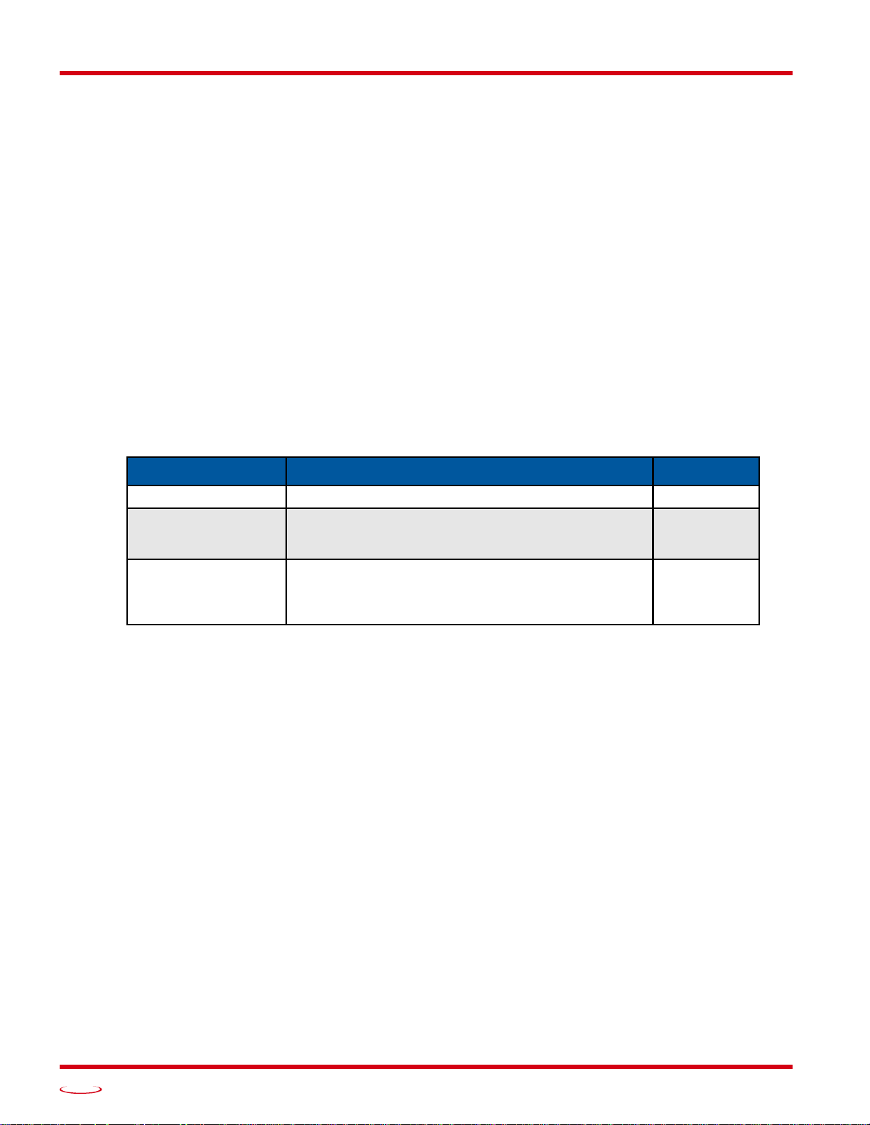
Chapter Title Chapter Description Starting Page
Analog DC60 User Manual
DC60 Specifications Complete specifications of the DC60 products. 7
Task instructions that give you the information and steps
Physical Installation
Wire Power and I/O
needed to physically install an DC60 encoder on your
machine.
Task instructions that give you the information and steps
needed to wire power and I/O connections to the DC60.
These instructions are applicable to both bench top and
machine wiring.
13
17
6
ADVANCED MICRO CONTROLS INC.
Page 7
Overview
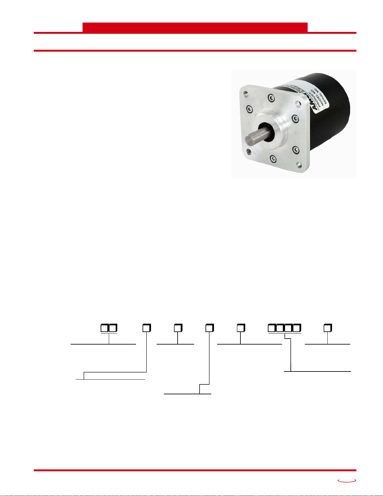
Figure 1 DC60 Resolver Based Encoder
E = End Connector
MOUNTING
F1 = 2.65" Square Flange
S1 = 58mm Servo Mount
SHAFT DIA.
1 = 0.375" dia.
3 = 0.250" dia.
4 = 6 mm dia.
6 = 10 mm dia.
OUTPUT TYPE
C = Current Output
V = Voltage Output
OUTPUT CODING
1 = 4 to 20 mA
2 = 0 to 20 mA
1 = 0 to +10 Vdc
Output Type = “V”
Output Type = “C”
SHAFT SEAL
V = Viton Seal, Aluminum Body
Notes:
0.375" dia x 0.884" long , w/ 0.047" x 0.77" flat
0.250" dia x 0.884" long, w/ 0.033" x 0.77" flat
6 mm dia x 10.25 mm long, w/ 0.3 mm x 9.5 mm flat
10 mm dia x 20.25 mm long, w/ 0.5 mm x 19.5 mm flat
The DC60 is a new line of heavy-duty resolver based encoder
products from AMCI. The first units to be released in this line
are absolute multi-turn encoders that offer a current or voltage
analog output.
Units can be ordered with a full scale output over any number
of turns between 1 and 1,024. The analog output has sixteen
bit resolution regardless of the number of turns encoded.
A flange mount unit with its connector on the end is shown in
figure
2.5 inch flange mount
58 mm servo mount
The following shaft options are available with both mounting
styles
0.375" dia x 0.884" long, w/ 0.047" x 0.77" flat
0.250" dia x 0.884" long, w/ 0.033" x 0.77" flat
6 mm dia x 10.25 mm long, w/ 0.3 mm x 9.5 mm flat
10 mm dia x 20.25 mm long, w/ 0.5 mm x 19.5 mm flat
The following current outputs are available:
DC60 SPECIFICATIONS
1. The following mounting styles are available:
The following voltage output is available:
An industry standard M12, 8 pin, A-coded, male connector is used as the power and I/O con nector. Both end
(axial) and side (radial) connector placement options are available. The body material of the DC60 units is
aluminum with a powder coat finish. Outline drawings of all of the packing options are available in the
line Drawings section of the manual starting on page 14.
Part Number Description
4 to 20 mA
0 to 20 mA
0 to +10 Vdc
DC60
B = Nitrile Seal, Aluminum Body
–
Out-
CONNECTOR
S = Side Connector
OUTPUT PERIOD
0001 to 1024:
# of turns for full scale output
Figure 2 Part Number Description
20 Gear Drive, Plymouth Ind. Park, Terryville, CT 06786
Tel: (860) 585-1254 Fax: (860) 584-1973 http://www.amci.com
7
Page 8
DC60 SPECIFICATIONS
Turck FS 8 or equ.
1
2
37
6
4
5
8
Connector Location and Pinout
M12 Connector
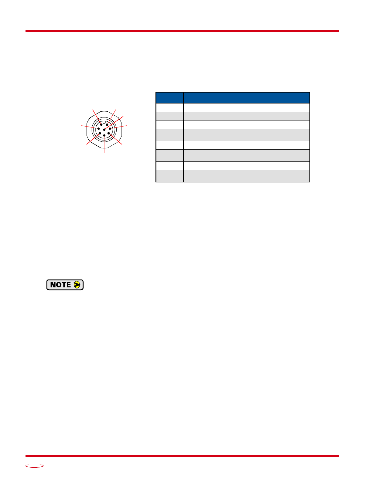
An eight pin, A-coded, male M12 connector is used on these DC60 units. It is located on the back or side of
the unit. This connector is the Turck eurofast FS 8 or equivalent. The pinout for the connector is shown
below.
Analog DC60 User Manual
Pin Single Ended Outputs
1 +DC Power Input
2 DC Return (GND)
3 Preset to Zero Input
4 No Function, Attach to DC Return
5 Analog Output
6 No Function, Attach to DC Return
7 Direction Control Input
8
Figure 3 I/O Connector Pinout
Pin 1: +DC Power Input: Input pin to power the DuraCoder. Requires a 10 to 30Vdc power supply at a max-
imum of 3.0 watts. This power draw does not include the current through the analog output.
Pins 2 and 8: DC Return: The return for the DC power supply and ground reference for both the digital
inputs and the analog output signal.
Pin 3: Preset to Zero Input: This pin is internally tied high to the +DC Input Power , (Pin 1) thro ugh a pull up
resistor. A high-to-low transition on this pin will preset the analog output to its minimum value. (In the case
of a 4 to 20 mA output, the output becomes 4 mA. In the case of a 0 to 10 Vdc Output, the output becomes 0
Vdc.) Therefore, this pin must be pulsed to ground (Pins 2 or 8) to preset the position. This input is heavily
filtered to prevent an accidental preset during normal operation, so the minimum pulse duration is 2,000 mil
liseconds.
All DC60 encoders use a nonvolatile memory technology known as F-RAM. Unlike older
memory technologies such as EEPROM, F-RAM does not have a limit on the number of times
the memory can be written to. You can preset the position as often as necessary in your appli
cation.
Pins 4 and 6: No Function: These pins can be left open if you are fabricating a custom cable. If a cordset is
used, these pins should be tied to DC Return (pins 2 and 8) for normal operation to prevent them from picking
up any electrical noise in the environment.
Pin 5: Analog Output: This pin is the analog output and it is referenced to DC Return (pins 2 and 8).
DC Return (GND)
-
-
Pin 7: Direction Control: This pin controls which direction the shaft must rotate in to increase the analog out-
put. The default is CW increasing output when looking at the shaft. If you are fabricating a custom cabl e and
want CW increasing output, this pin can be left open or attached to +DC Power Input (pin 1). Connecting this
pin to DC Return (pins 2 or 8), forces the output to increase with CCW rotation. If using a molded cordset,
connect the wire on this pin to either +DC Input Power or DC Return for normal operation. Do not leave the
wire floating.
8
ADVANCED MICRO CONTROLS INC.
Page 9
Analog DC60 User Manual
Status LED
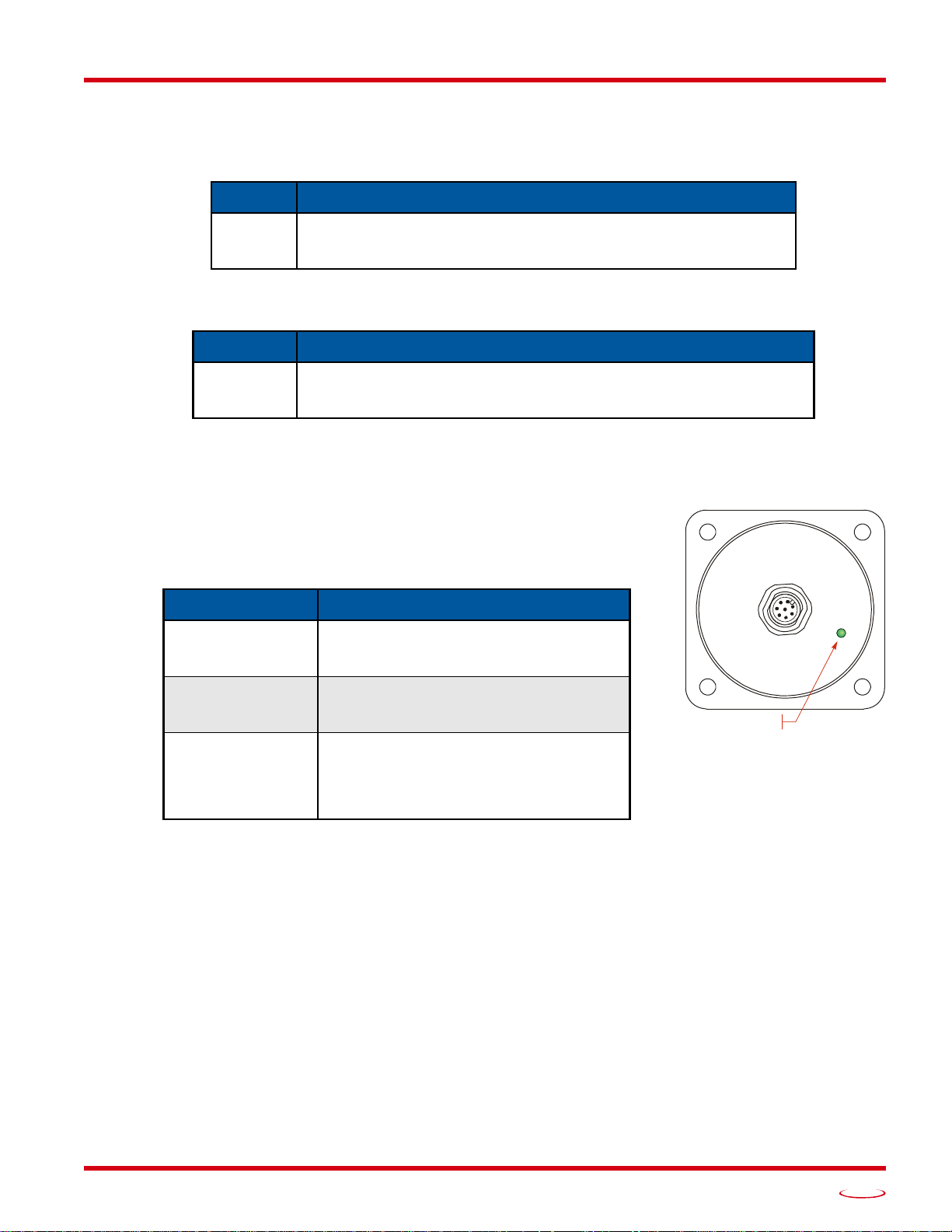
Figure 4 Status LED Location
Mating Connector and Cordsets
The following mating connector is available from AMCI. Note that any commercially available M12 connectors with the proper coding and contacts can be used.
AMCI # Description
Female, A-coded, 8 contacts. Screw terminal connections.
AMCI offers the followin
Status LED
Each DC60 has a Status LED on its rear cover . Figure 4 shows an end connect
unit. The LED is in the same location on side connect units. This LED indicates whether or not output is driving a load (cable break detect ion) and gives
a rough indication of the value of the analog output when it is driving a load.
Table
MS-37
AMCI # Description
CNFL-5M
3 shows the different blink patterns.
6 to 8 mm dia. cable. Maximum 20 AWG wire dia.
Straight, IP67 rated when properly installed.
g cordset fo
Molded cordset. 5 meters in length.
Straight M12 8 pin A-coded to flying leads
IP67 rated when properly installed.
DC60 SPECIFICATIONS
Table 1 Available Mating Connectors
r use with the DC60.
Table 2 Available Cordsets
Rear View
Blink Pattern Description
Alternating
Red/Green
Blinking Green
50% duty cycle
The DC60 is not driving a load. Most common causes are a mis-wiring or brake in the
cable.
The DC is driving a load and the shaft is
rotating. The LED is on for 1 second, off
for 1 second.
When the analog output is at its minimum,
Blinking Green
10 to 90% duty cycle
the duty cycle will be 10%. When the ana
log output is at its maximum, the duty cycle
will be 90%. The period is two seconds, so
the minimum on time is 0.2 seconds.
Table 3 Status LED Blink Patterns
-
20 Gear Drive, Plymouth Ind. Park, Terryville, CT 06786
Tel: (860) 585-1254 Fax: (860) 584-1973 http://www.amci.com
9
Page 10
DC60 SPECIFICATIONS
Maximum Load Resistance (ohms)
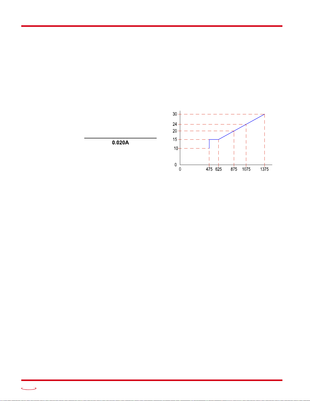
R =
LOAD
MAX
(+DC Input Voltage) – 2.5Vdc
Output Load Calculations
Voltage Output DuraCoder
A voltage output DuraCoder can drive an output load of 2 k or greater. If the output load is greater that
10 k, consider installing a 10 k resistor in parallel with the input terminals for greater noise immunity.
Current Output DuraCoder
The maximum load that can be driven by a current output DuraCoder depends on the power supply voltage
applied to the +DC Power Input (Pin 1). For input voltages up to 15 Vdc, the maximum load is 475
input voltages greater than or equal to 15 Vdc, the formula for determining the maximum load is given below
along with a simple graph of the curve.
Analog DC60 User Manual
. For
+DC Input Voltage
Figure 5 Maximum Load Resistance - Current Output
10
ADVANCED MICRO CONTROLS INC.
Page 11

Analog DC60 User Manual
DC60 SPECIFICATIONS
Electrical Specifications
Operating Voltage
10 Vdc to 30 Vdc maximum
Power Requirements
1.0 W max.
30 mA @ 24 Vdc typical
Value is the operating power and does not
include current supplied by the analog output.
Position Resolution
16 bit (1 part in 65,536)
Position Accuracy
±10 arc-minutes
Position Update Time
1.6 milliseconds
Maximum Output Settling Time
50 microseconds when switching between mini-
mum and maximum outputs
Direction of Increasing Counts
Default CW looking at shaft
Can be set to CCW increasing by shorting the
Direction Control Input pin (pin 7) to DC
Return.
Zero Position
Can be set by pulsing the Preset to Zero Input pin
(pin 3) from DC Return to open circuit or +DC
Power. Minimum pulse width of 2,000 mi llisec
onds.
Mechanical Specifications
Package Style
60 mm housing with flange or servo mounting
Mechanical Specifications (continued)
Connector Location
End
Housing
Powder coated aluminum
Available Shafts
0.250", 0.375", 6 mm, or 10 mm.
All shafts have flats.
Max. Starting Torque @ 25°C
2.0 oz-in (1.41 N·cm)
Moment of Inertia
6.0 X 10⁻⁴ oz-in-sec2 (43.2 X 10⁻⁶ kg-cm-sec2)
Max. Operating Speed
6000 RPM max.
Max. Shaft Loading
Axial: 20 lbs. (89 N)
Radial: 40 lbs. (178 N)
At specified max. loads, minimum bearing life is
2X10
9
revolutions.
Environmental Specifications
Operating Temperature
–40°F to +185°F (–40°C to +85°C)
Shock
50g, 11 millisecond duration
-
Vibration
20 g, 5 to 2000 Hz
Enclosure Rating
IP67
Approximate Weight
1.3 lbs. (0.59 kg)
20 Gear Drive, Plymouth Ind. Park, Terryville, CT 06786
Tel: (860) 585-1254 Fax: (860) 584-1973 http://www.amci.com
11
Page 12

DC60 SPECIFICATIONS
Notes
Analog DC60 User Manual
12
ADVANCED MICRO CONTROLS INC.
Page 13
PHYSICAL INSTALLATION
This section is intended for the engineer or technician responsible for installing
the DC60 resolver based encoder . Information in this chapter include s inst allation
guidelines, links to online CAD files, and mechanical drawings.
1.1 Installation Guidelines
1.1.1 Electrostatic Discharge Prevention
Electrostatic discharge can damage the DC60 if the discharge is through the I/O connector. Follow these
guidelines when handling the unit.
1) Touch a grounded object to discharge static potential before handling the unit.
2) Work in a static-safe environment whenever possible.
3) Do not touch the pins of the I/O connector.
4) Do not disassemble the unit
1.1.2 Suitable Environment
The DC60 has an IP67 environmental rating and can be installed in most industrial environments, including
areas subject to washdown spray and temporary immersion.
REQUIRED TASK
The IP67 rating is contingent on the proper installation of the mating connector.
1.1.3 Shaft Loading
A flexible coupler should be used when connecting a DC60 to a drive shaft, because any mismatch in shaft
alignment will result in large radial or axial loading on the shaft of the encoder. Limit shaft loading to the fol
lowing values. These values statistically yield an L10 life of 2X10⁹ revolutions. (Statistically, only 10% of
the bearings will have failed after 2X10
The effect is actually cubic. Cutting a shaft load in half will result in an eight fold increase in bearing life.
Radial Load Axial Load
40 lbs. (178 N) 20 lbs. (88 N)
Table 1.1 DC60 Maximum Shaft Loading Specifications
1.1.4 A Note on Cable Direction
All of the dimensional drawings in the Outline Drawings section (1.3), show the direction that the cable exits
when using right angle connectors. Use this information to properly route cables when designing the DC60
mounting.
1.2 Availability of CAD Drawings
CAD drawing for all DC60 devices are available on the AMCI website. Direct links to the files are:
http://www.amci.com/downloads/dwg/2D_DC60.zip
(DWG files compatible with AutoCAD R14+)
9
revolutions.) Shaft loading has an exponential effect on bearing life.
-
http://www.amci.com/downloads/step/3D_DC60.zip
(AP203 compatible STEP files.)
20 Gear Drive, Plymouth Ind. Park, Terryville, CT 06786
Tel: (860) 585-1254 Fax: (860) 584-1973 http://www.amci.com
13
Page 14
REQUIRED TASK: PHYSICAL INSTALLATION
(26.21)
(31.75)
typ.
(26.21)
typ.
C
C
(21.6)
Status LED location
(26.21)
(31.75)
typ.
(49.3)
typ.
C
C
Exit Direction of
Right Angle Cables
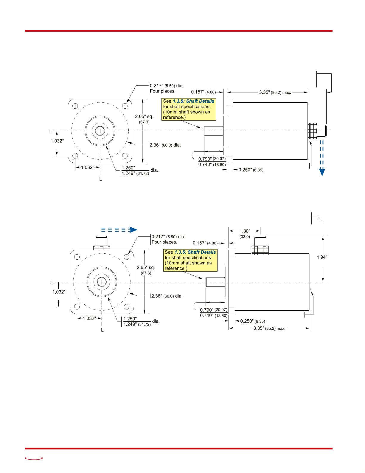
1.3 Outline Drawings
1.3.1 Flange Mount, Aluminum Body, End Connect
Analog DC60 User Manual
Figure 1.1 Flange Mount, End Connector Outline Drawing
1.3.2 Flange Mount, Aluminum Body, Side Connect
Additional clearance is needed for
the removal of the mating connectors.
Additional clearance is needed for
the removal of the mating connector.
0.85" max.
Exit Direction of
Right Angle Cables
(26.21)
Figure 1.2 Flange Mount, Side Connector Outline Drawing
Status LED locati on
max.
14
ADVANCED MICRO CONTROLS INC.
Page 15
Analog DC60 User Manual
C
(21.6)
C
Exit Direction of
Right Angle Cables
location
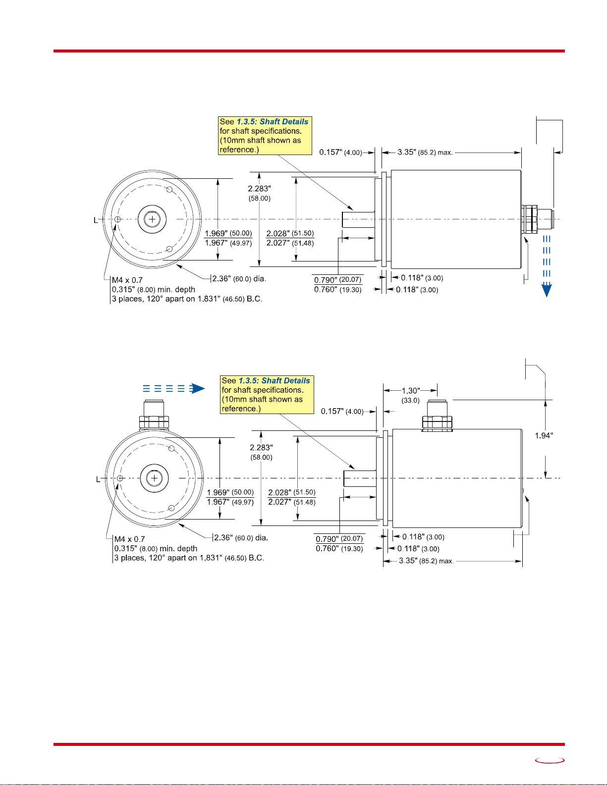
1.3 Outline Drawings (continued)
1.3.3 Servo Mount, Aluminum Body, End Connect
REQUIRED TASK: PHYSICAL INSTALLATION
Figure 1.3 Servo Mount, End Connector Outline Drawing
1.3.4 Servo Mount, Aluminum Body, Side Connect
Additional clearance is needed for
the removal of the mating connectors.
Additional clearance is needed for
the removal of the mating connector.
0.85" max.
Status LED locati on
Exit Direction of
Right Angle Cables
(49.3)
max.
Status LED
Figure 1.4 Servo Mount, Side Connector Outline Drawing
20 Gear Drive, Plymouth Ind. Park, Terryville, CT 06786
Tel: (860) 585-1254 Fax: (860) 584-1973 http://www.amci.com
15
Page 16
REQUIRED TASK: PHYSICAL INSTALLATION
(10.50)
1.3 Outline Drawings (continued)
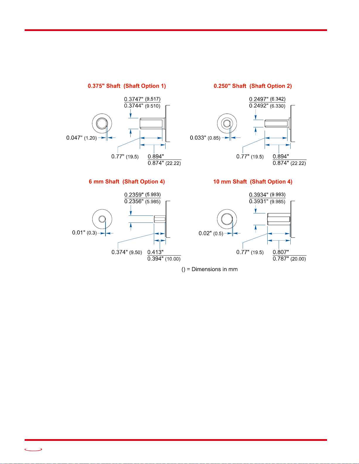
1.3.5 Shaft Details
The figure below shows the pilot of a flange mount nose. Listed dimensions are identical for the servo mount
option.
(22.72) (22.72)
Analog DC60 User Manual
Figure 1.5 Shaft Details
(20.50)
16
ADVANCED MICRO CONTROLS INC.
Page 17
REQUIRED TASK
1
5 Analog Output
2
6
Attach to DC Ground.
3 Preset to Zero Input
4
No Function.
Attach to DC Return.
7
8 DC Return (GND)
Power and I/O Connector
Status LED
Exit Direction of
Right Ang le Cables
WIRE POWER AND I/O
2.1 Wiring Guidelines
The DC60 requires a power supply of 10 to 30 Vdc, (12 to 24 Vdc nominally). Power requirement is 1.0 watts
maximum, with 30 mA @ 24Vdc typical. This power draw does not include the current through the analog
output.
Signals from the DC60 are low voltage, low power signals. Cables should not be run with high power
AC or DC cabling.
Signal cable can be run in conduits with other low power AC and DC signal cables. Ideally, cable will
be run in metal conduit that is bonded along its entire length.
Signal cable should not be run in parallel with high power AC or DC cabling to minimize capacitive
coupling of electrical noise. If they must be run in parallel, separate them as much as possible.
If a signal cable must cross high power AC or DC cabling, it should do so at a right angle to minimize
inductive coupling of electrical noise.
2.2 Connector Location and Pinout
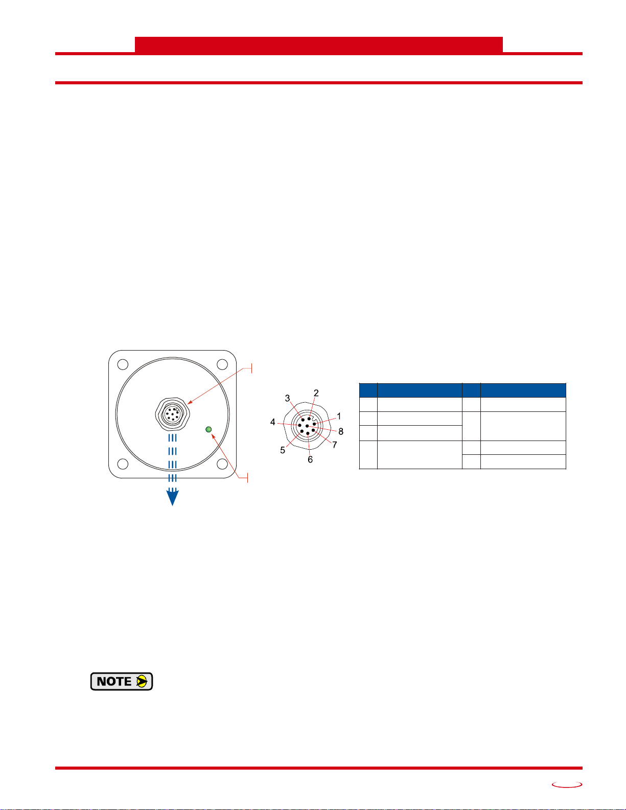
2.2.1 Connector Pinout
Figure 2.1 below shows the location of the power and I/O connector location as well as the connector pinout.
Rear View
Figure 2.1 DC60 Connector Placement
Pin 1: +DC Power Input: Input pin to power the DuraCoder. Requires a 10 to 30Vdc power supply at a max-
imum of 3.0 watts. This power draw does not include the current through the analog output.
Pins 2 and 8: DC Return: The return for the DC power supply and ground reference for both the digital
inputs and the analog output signal.
Pin 3: Preset to Zero Input: This pin is internally tied high to the +DC Input Power , (Pin 1) thro ugh a pull up
resistor. A high-to-low transition on this pin will preset the analog output to its minimum value. (In the case
of a 4 to 20 mA output, the output becomes 4 mA. In the case of a 0 to 10 Vdc Output, the output becomes 0
Vdc.) Therefore, this pin must be pulsed to ground (Pins 2 or 8) to preset the position. This input is heavily
filtered to prevent an accidental preset during normal operation, so the minimum pulse duration is 2,000 mil
liseconds.
All DC60 encoders use a nonvolatile memory technology known as F-RAM. Unlike older
memory technologies such as EEPROM, F-RAM does not have a limit on the number of times
the memory can be written to. You can preset the position as often as necessary in your appli
cation.
20 Gear Drive, Plymouth Ind. Park, Terryville, CT 06786
Tel: (860) 585-1254 Fax: (860) 584-1973 http://www.amci.com
Pin Description Pin Description
+DC Power Input
DC Return (GND)
Factory Programming.
Direction Control Input
-
-
17
Page 18
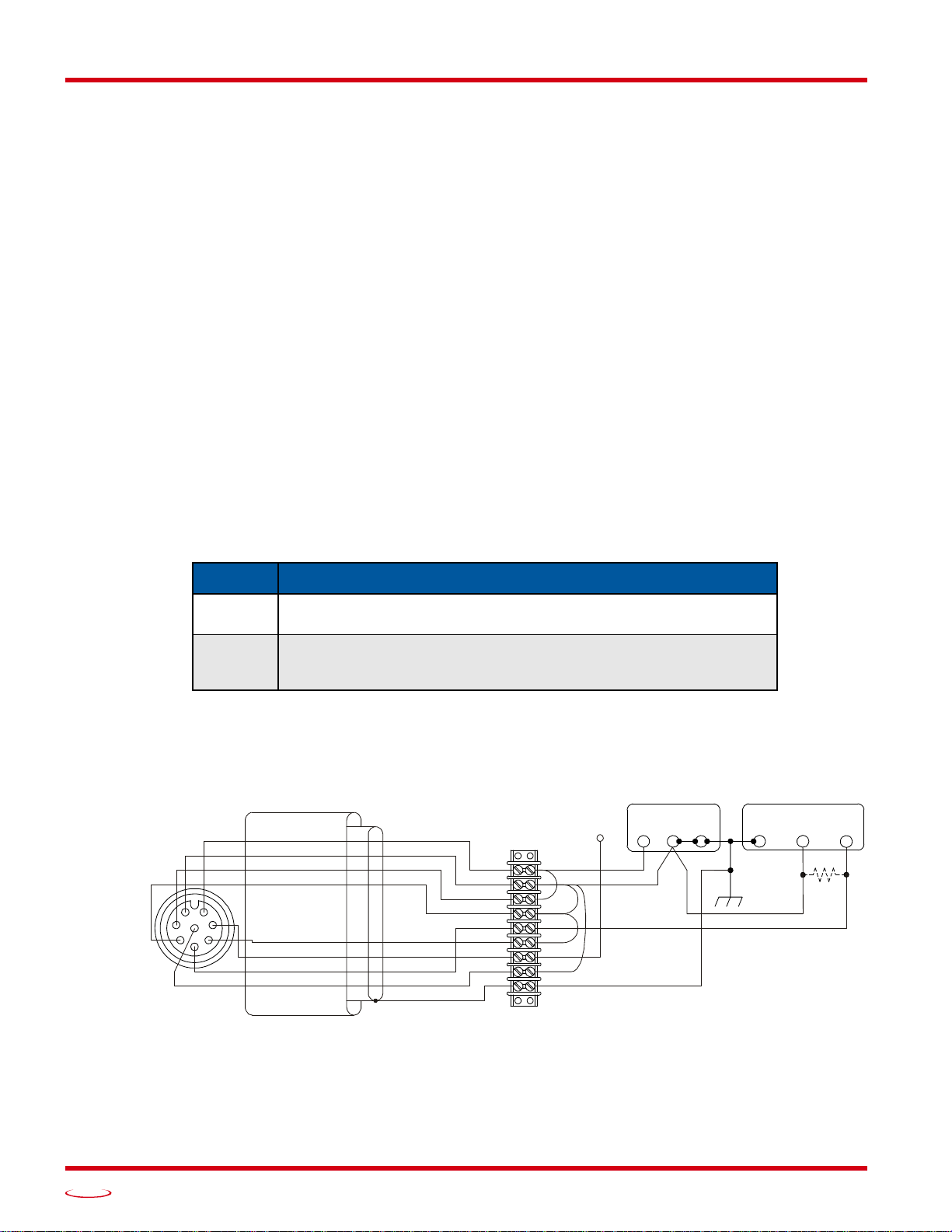
WIRE POWER AND I/O
+DC Po wer Input
DC Return
Preset To Zero
No Function
Analog Out
No Function
Direction Control
DC Return
PNK
GRY
RED
1
2
3
4
5
6
7
8
DRAIN
BLU
M12 Connector
Female, A-coded, 8-pin
View from back of connector
Notes:
Color code is for the CNFL-5M cable available from AMCI.
The Preset to Zero pin should be attached to +DC Power Input for normal operation.
No Function pins should be grounded for normal operation.
+Vdc
-IN
+IN
POWER SUPPLY
INPUT DEVICE
-Vdc
GND
AMCI CNFL-5M Cable
2.2 Connector Location and Pinout (continued)
2.2.1 Connector Pinout (continued)
Pins 4 and 6: No Function: These pins can be left open if you are fabricating a custom cable. If a cordset is
used, these pins should be tied to DC Return (pins 2 and 8) for normal operation to prevent them from picking
up any electrical noise in the environment.
Pin 5: Analog Output: This pin is the analog output and it is referenced to DC Return (pins 2 and 8).
Pin 7: Direction Control: This pin controls which direction the shaft must rotate in to increase the analog out-
put. The default is CW increasing output when looking at the shaft. If you are fabricating a custom cabl e and
want CW increasing output, this pin can be left open or attached to +DC Power Input (pin 1). Connecting this
pin to DC Return (pins 2 or 8), forces the output to increase with CCW rotation. If using a molded cordset,
connect the wire on this pin to either +DC Input Power or DC Return for normal operation. Do not leave the
wire floating.
2.2.2 Right Angle Cable Exit Direction
When designing a mounting solution for the DC60, be aware of the cable exit direction when using right
angle mating connectors. Figure
Phoenix Contact cordsets.
2.2.3 Mating Connectors and Cordsets
AMCI offers the following mating connector and cordsets that mate with the NR60 power connector. Note that
the power connector will mate with any connector or cordset that follows the M12, 4 pin, A-coded standard.
2.1 above shows the direction of the cable when using AMCI, TRUCK, or
Analog DC60 User Manual
2.3 Sample Wiring Diagram
18
AMCI # Description
MS-37
Screw terminal connections. 6 to 8 mm dia. cable. 20 AWG max.
Straight, IP67 rated when properly installed.
Molded cordset. 5 meters in length.
CNFL-5M
Straight M12 8 pin A-coded to flying leads
IP67 rated when properly installed.
Table 2.1 Compatible Connectors and Cordsets
The diagram below shows how to wire a DC60 encoder using the CNFL-5M cable from AMCI.
CHASSIS
WHT
BRN
GRN
YEL
The Direction Control pin should be tied to +DC Power for CW increasing output or DC Return for CCW increasing output.
For voltage output, if input impedance exceeds 10 kohm, consider installing a 10 kohm resistor to improve noise immunity.
Figure 2.2 Sample Wiring Diagram
GND
ADVANCED MICRO CONTROLS INC.
Page 19

Analog DC60 User Manual
Notes
WIRE POWER AND I/O
20 Gear Drive, Plymouth Ind. Park, Terryville, CT 06786
Tel: (860) 585-1254 Fax: (860) 584-1973 http://www.amci.com
19
Page 20

ADVANCED MICRO CONTROLS INC.
20 GEAR DRIVE, TERRYVILLE, CT 06786 T: (860) 585-1254 F: (860) 584-1973
www.amci.com
Waste Electrical and Electronic Equipment (WEEE)
At the end of life, this equipment should be collected separately from any unsorted municipal waste.
 Loading...