


|
|
ST TUNED |
TAPE M |
PRESET |
|
|
|
dB |
MEM |
|
|
|
|
|
|
|
|
kHz |
|
|
|
|
MHz |
|
|
|
|
|
ms |
DTS |
DIGITAL |
Pro Logic |
THEATERHALL12 |
SLEEP |
Introduction
UNPACKING AND INSTALLATION
Congratulations on Your Purchase!
Your new high fidelity receiver is designed to deliver maximum enjoyment and years of trouble free service. Please take a few moments to read this manual thoroughly. It will explain the features and operation of your unit and help ensure a trouble free installation. Please unpack your unit carefully. We recommend that you save the carton and packing material. They will be helpful if you ever need to move your unit and may be required if you ever need to return it for service. Your unit
is designed to be placed in a horizontal position and it is important to allow at least two inches of space behind your unit for adequate ventilation and cabling convenience. To avoid damage, never place the unit near radiators, in front of heating vents, in direct sunlight, or in excessively humid or dusty locations. Connect your complementary components as illustrated in the following section.
CAUTION : TO REDUCE THE RISK OF |
ELECTRIC SHOCK, DO NOT |
REMOVE COVER (OR BACK). |
NO USER-SERVICEABLE PARTS |
INSIDE. REFER SERVICING TO |
QUALIFIED SERVICE PERSONNEL. |
This symbol is intended to alert the user to the presence of uninsulated "dangerous voltage" within the product's enclosure that may be
of sufficient magnitude to constitute a risk of electric shock to persons.
This symbol is intended to alert the user to the presence of important operating and maintenance (servicing) instructions in the literature accompanying the appliance.
WARNING
To reduce the risk of fire or electric shock, do not expose this appliance to rain or moisture.
Caution : Do not block ventilation openings or stack other equipment on the top.
FOR U.S.A.
<Note to CATV System Installer: This reminder is provided to call the CATV system installer's attention to Article 820-40 of the NEC that provides guidelines for proper grounding and, in particular, specifies that the cable ground shall be connected to the grounding system of the building, as close to the point of cable entry as practical.
<FCC INFORMATION
This equipment has been tested and found to comply with the limits for a Class B digital device, pursuant to Part 15 of the FCC Rules. These limits are designed to provide reasonable protection against harmful interference in a residential installation. This equipment generates, uses and can radiate radio frequency energy and, if not installed and used in accordance with the instructions, may cause harmful interference to radio communications. However, there is no guarantee that interference will not occur in a particular installation. If this equipment does cause harmful interference to radio or television reception, which can be determined
by turning the equipment off and on, the user is encouraged to try to correct the interference by one or more of the following measures:
=Reorient or relocate the receiving antenna. =Increase the separation between the equipment
and receiver.
=Connect the equipment into an outlet on a circuit different from that to which the receiver is connected.
=Consult the dealer or an experienced radio/TV technician for help.
CAUTION : Any changes or modifications in construction of this device which are not expressly approved by the party responsible for compliance could void the user's authority to operate the equipment.
Caution regarding placement (Except for U.S.A and Canada)
To maintain proper ventilation, be sure to leave a space around the unit (from the largest outer dimensions including
projections) equal to, or greater than, shown below.
Left and right panels : 5 cm
Rear panel : 10 cm
Top panel : 20 cm
2
READ THIS BEFORE OPERATING YOUR UNIT
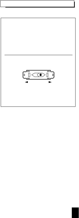
AC VOLTAGE SELECTION............................ |
115 V/230 V |
This unit operates on 115-230 V AC. The AC voltage selector switch on the rear panel is set to the voltage that prevails in the area to which the unit is shipped. Before connecting the power cord to your AC outlet, make sure that the setting position of this switch matches your line voltage. If not, it must be set to your voltage in accordance with the following direction.
AC voltage selector switch
AC 230 V |
|
|
|
AC 115 V |
|
|
Move switch lever to match |
your |
line voltage |
with a small screwdriver or |
other |
pointed tool. |
3

CONTENTS |
|
Introduction |
|
=UNPACKING AND INSTALLATION ........................................................................................................ |
2 |
=READ THIS BEFORE OPERATING YOUR UNIT ................................................................................... |
3 |
System Connections........................................................................................................................................ |
5 |
Front Panel Controls...................................................................................................................................... |
8 |
Remote Controls.............................................................................................................................................. |
9 |
=REMOTE CONTROL OPERATION RANGE.......................................................................................... |
10 |
=LOADING BATTERIES............................................................................................................................ |
10 |
Operations |
|
=LISTENING TO A PROGRAM SOURCE ................................................................................................ |
11 |
=SURROUND SOUND ............................................................................................................................... |
14 |
=ENJOYING SURROUND SOUND........................................................................................................... |
15 |
=LISTENING TO RADIO BROADCASTS................................................................................................ |
19 |
=RECORDING............................................................................................................................................. |
21 |
=OTHER FUNCTIONS ............................................................................................................................... |
22 |
Using the OSD |
|
=CURRENT STATUS DISPLAY................................................................................................................. |
23 |
=MENU SCREEN........................................................................................................................................ |
23 |
Troubleshooting Guide ................................................................................................................................ |
26 |
Specifications.................................................................................................................................................. |
27 |
4

System Connections
=Do not connect the receiver to the wall AC outlet when plugging and unplugging connection cords.
=Be sure to connect the white RCA pin cords to the L(left) and the red RCA pin cords to the R(right) jacks when making connections.
=Change the position of the FM indoor antenna until you get the best reception of your favorite FM stations. =A 75 outdoor FM antenna may be used to further improve the reception.
Disconnect the indoor antenna before replacing it with the outdoor one.
=Place the AM loop antenna as far as possible from the receiver, TV set, speaker cords and the AC input cord and set it to a direction for the best reception.
=If the reception is poor with the AM loop antenna, an AM outdoor antenna can be used in place of the AM loop antenna. =Make connections firmly and correctly. If not, it can cause loss of sound, noise or damage to the receiver.
=If the electricity fails or the AC input cord is left unplugged for about 2 weeks, the memorized contents will be cleared. Should this happen, memorize them again.
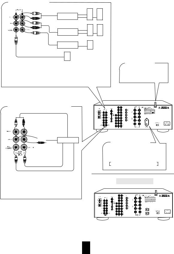
CONNECTING AUDIO COMPONENTS
Tape deck or additional audio component
PLAY(LINE OUT)
HX-PRO
B A
CD player
PLAY(LINE
The TAPE MONITOR connected to the LINE graphic equalizer.
CONNECTING ANTENNAS
FM
(OUTDOOR ANTENNA)
FM
(INDOOR ANTENNA) |
AM loop antenna |
300 ohm feeder
CONNECTING VIDEO COMPONENTS
|
Monitor TV |
|
S-VIDEO IN |
IN VIDEO |
Video deck 2 |
|
|
|
S-VIDEO OUT |
OUT VIDEO |
OUT AUDIO |
|
Video deck 1 |
IN AUDIO |
|
VIDEO IN |
AUDIO OUT |
||
|
|||
VIDEO OUT |
|
S-VIDEO IN |
|
|
DVD player |
S-VIDEO OUT |
|
|
|
||
VIDEO OUT |
|
AUDIO OUT |
|
|
|
S-VIDEO OUT |
The VCR 2(or DVD) jacks may also be connected to an additional video component such as a cable TV tuner, a LD player or satellite system.
Use the S-VIDEO jacks to make connections to video components with S-VIDEO IN/OUT jacks. A signal input into the S-VIDEO jack will be output in only the S- VIDEO jack and a signal input into the normal VIDEO jack will be output in only the normal VIDEO jack.
SUPPLIED ADAPTOR
5
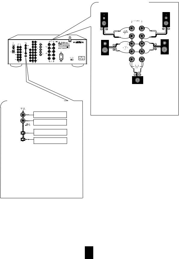
CONNECTING SPEAKERS
Front right |
|
|
|
Front left |
|||
|
|
|
|
|
|
|
|
|
|
|
|
|
|
|
|
|
|
|
|
|
|
|
|
|
|
|
|
|
|
|
|
|
|
|
|
|
|
|
|
|
|
|
|
|
|
|
|
|
|
|
|
|
|
|
|
Rear |
Rear |
|
right |
||
left |
||
|
CONNECTING DIGITAL INPUTS
Component with
COAXIAL DIGITAL OUT
Component with
COAXIAL DIGITAL OUT
Component with
OPTICAL DIGITAL OUT
Component with
OPTICAL DIGITAL OUT
The COAXIAL or the OPTICAL DIGITAL OUTs of the components that are connected to "CD", "VCR2" and "DVD" of this unit can be connected to these DIGITAL INPUTS.
A digital input should be connected to the components such as LD player, CD player or DVD player, etc. capable of outputing DTS Digital Surround, Dolby Digital or PCM format digital signals.
For details, refer to the operating instructions of the component connected.
When making the COAXIAL DIGITAL connection, be sure to use a 75 COAXIAL cord, not a conventional AUDIO cord.
Center
Never short circuit the + and - speaker cords.
Be sure to connect speakers firmly and correctly according to the channel (left and right) and the polarity (+ and -).
Be sure to use the speakers with the impedance of over 8 . For installing the speakers, refer to "Speaker placement" on page 14.
6
PRE OUT connections
Power amplifier
Power amplifier
Power amplifier
Front speakers
Rear speakers
Center speaker
Powered subwoofer
Use these jacks when adding additional amplifiers.
Connect the PRE OUT jacks to the powered speakers or the power amplifiers connected to speakers respectively.
To emphasize the deep bass sounds, connect a powered subwoofer.
CONNECTING 6 CH DIRECT INPUTS
FRONT CH OUT
AC INPUT CORD
Plug this cord into a wall AC outlet.
Manufactured under license from Dolby Laboratories. "Dolby", "Pro Logic" and the double-D symbol are trademarks of Dolby Laboratories. ConfidentialUnpublished Works.
1992-1997 Dolby Laboratories, Inc. All rights reserved.
Manufactured under license from Digital Theater Systems, Inc.
US Pat. No. 5,451,942 and other world-wide patents issues and pending. "DTS" and "DTS Digital surround" are trademarks
of Digital Theater Systems, Inc.
1996 Digital Theater Systems, Inc. All Rights Reserved.
REAR


 CH OUT 6 CH decoder
CENTER CH OUT
SUBWOOFER CH OUT
Use these jacks to connect the corresponding analog outputs of 6 CH decoder or DVD player with 6 CH output for Dolby Digital or DTS, etc.
(For details, see the operator's manual of the component to be connected.)
SWITCHED AC OUTLET
This outlet is switched on(power-on mode) and off(standby mode) according to power controls as follows(Maximum total capacity is 100W):
Standby mode Ð switched AC outlet off
Power-on mode Ð switched AC outlet on
AMERICAN VERSION
Manufactured under license from Dolby Laboratories. "Dolby", "Pro Logic" and the double-D symbol are trademarks of Dolby Laboratories. ConfidentialUnpublished Works.
1992-1997 Dolby Laboratories, Inc. All rights reserved.
Manufactured under license from Digital Theater Systems, Inc.
US Pat. No. 5,451,942 and other world-wide patents issues and pending. "DTS" and "DTS Digital surround" are trademarks
of Digital Theater Systems, Inc.
1996 Digital Theater Systems, Inc. All Rights Reserved.
7
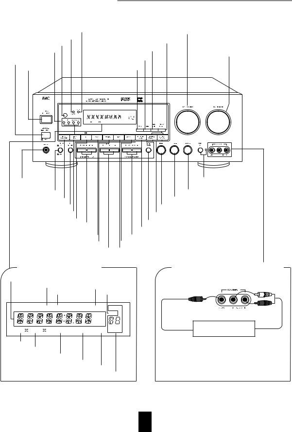
Front Panel Controls
DYNAMIC RANGE INDICATOR |
|
|
|
|
INPUT SELECTOR KNOB |
STANDBY INDICATOR |
|
|
|
|
|
|
|
|
TUNING/PRESET BUTTON |
||
REMOTE SENSOR |
|
|
|
||
|
|
|
|
|
|
DIGITAL INPUT INDICATORS |
|
|
MEMORY/ENTER BUTTON |
MASTER VOLUME |
|
|
|
|
|
CONTROL KNOB |
|
MAIN POWER |
|
|
MONO BUTTON |
||
|
|
|
|||
SWITCH |
|
|
|
|
|
POWER BUTTON |
|
|
AM FM BUTTON |
|
|
|
|
ST TUNED |
TAPE M |
PRESET |
|
|
|
|
dB |
MEM |
|
|
|
|
|
|
|
|
|
|
kHz |
|
|
|
|
|
MHz |
|
|
|
|
|
|
ms |
|
DTS |
DIGITAL |
Pro Logic |
THEATER HALL12 |
SLEEP |
|
HEADPHONE |
TONE DIRECT |
|
JACK |
BUTTON/INDICATOR |
|
SPEAKER SWITCH |
BALANCE CONTROL KNOB |
|
VIDEO SELECTOR BUTTON |
TREBLE CONTROL KNOB |
|
6 CH DIRECT BUTTON |
BASS CONTROL KNOB |
|
DIGITAL INPUT BUTTON |
TUNING/PRESET UP/DOWN( / ) BUTTONS |
|
|
||
DTS/DOLBY SURROUND BUTTON |
REAR BALANCE BUTTON |
|
CENTER LEVEL |
||
SPEAKER MODE BUTTON |
||
UP/DOWN( / ) BUTTONS |
||
|
||
S.S.E. BUTTON |
REAR LEVEL UP/DOWN( / ) BUTTONS |
|
STEREO BUTTON |
DYNAMIC RANGE BUTTON |
|
SUBWOOFER LEVEL UP/DOWN( / ) BUTTONS |
TAPE BUTTON |
FLUORESCENT DISPLAY
INPUT, FREQUENCY, VOLUME LEVEL, OPERATING INFORMATION, etc.
STEREO INDICATOR |
TAPE MONITOR INDICATOR |
|
|
TUNED INDICATOR |
MEMORY INDICATOR |
|
|
ST |
TUNED |
TAPE M |
PRESET |
|
|
|
|
|
|
dB |
MEM |
|
|
|
|
|
|
|
|
|
|
|
|
kHz |
|
|
|
|
|
|
MHz |
|
|
|
|
|
|
|
ms |
DTS |
DIGITAL |
Pro Logic |
THEATER |
HALL12 |
SLEEP |
|
DTS INDICATOR
DOLBY(
 ) DIGITAL INDICATOR
DOLBY(
 ) PRO LOGIC INDICATOR THEATER INDICATOR
HALL INDICATORS
PRESET NUMBER, SLEEP TIME, DELAY TIME DISPLAY
VCR 3 VIDEO/AUDIO INPUT JAKCS
Additional video component
OUT |
OUT |
The VCR 3 jacks may be also connected to an additional video component such as a camcorder, an LD plyaer or a video game player, etc.
8
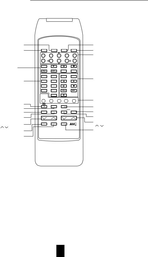
Remote Controls
ON SCREEN DISPLAY BUTTON
POWER BUTTON |
POWER |
OSD |
|
ENTER |
P.SCAN |
|
|
|
|
|
|
|
1 |
2 |
3 |
4 |
5 |
|
6 |
7 |
8 |
9 |
0 |
DVD PLAYER BUTTONS |
DISC |
|
|
|
|
DVD |
|
|
REPEAT |
INTRO |
|
|
|
|
|
A B |
SCAN |
|
CD |
TUNER |
|
DECK SEL. |
|
|
|
|
|
A |
B |
INPUT SELECTOR BUTTONS |
AUX |
TAPE MON. |
|
|
|
DVD/TV |
VCR1 |
|
|
|
|
In the standby mode, when pressing an input |
|
|
|
||
selector button, the unit is turned on automatically |
VCR2 |
VCR3 |
|
|
|
and the desired input source is selected. |
|
|
|
||
|
|
|
|
|
|
|
|
6CH DIRECT |
|
|
|
|
EQ |
|
|
|
DECK |
|
PRESET |
USER |
FILE |
DISPLAY |
T.MON |
DTS/DOLBY SURROUND BUTTON |
|
DSP |
|
STEREO |
|
DSP MODE BUTTON |
|
MODE |
|
|
|
CHANNEL |
T.TONE |
|
D.TIME |
ADJUST |
|
CHANNEL SELECTOR BUTTON |
|
||||
SEL. |
|
|
|
|
|
TEST TONE BUTTON |
CHANNEL LEVEL |
|
MASTER VOLUME |
||
|
|
|
|
|
|
CHANNEL LEVEL UP/DOWN |
DISPLAY |
SLEEP |
|
MUTE |
|
SYS |
|
|
|
|
|
( / ) BUTTONS
DISPLAY BUTTON
REMOTE CONTROL R9
SLEEP BUTTON
ENTER BUTTON
PRESET SCAN BUTTON
NUMERIC(1~0)/CURSOR CONTROL ( ,
, ) BUTTONS
For selecting preset stations in tuner mode.
For selecting the menus or changing the conditions of the items with the CURSOR CONTROL buttons in the ON-SCREEN DISPLAY mode.
TAPE DECK BUTTONS
EQUALIZER BUTTONS
STEREO BUTTON
DELAY ADJUST BUTTON
DELAY TIME BUTTON
MASTER VOLUME UP/DOWN ( / ) BUTTONS
MUTE BUTTON
Note:
=The buttons for DVD player, tape deck and equalizer cannot be available.
9
 Loading...