

Page 1
HOME
Entertainment
Genter
AMC
.l
--6
et-
-o
o"9
so
oa
9C
e3
/^s
-o-
s"
?^,.
,r*
".tsa
lcrr
leat
INSTRUCTIONS
FOR
INSTALLATION
AND
OPERATION
Page 2
A
ffia
AffiA AffiA
CAUTION:
TO REDUCE
THE
RISK
OF
ELECTRIC
SHOCK,
DO NOT REMOVE
COVER
(OR
BACKT
NO USER.SERVICEABLE
PARTS
INSIDE, REFER
SERVICING
TO
QUALIFIED
SERVICE
PERSONNEL
AFIN DEVITER UN
CHOC
ELECTRIQUE
ET LES
CONSEQUEI'.ICES
GRAVES
QUI
POURRAIENT
EN RESULTER,
TENTEZ
PAS
D'OUVRIR L
APPAREII
ET DE TOUCHER
AUX
COMPOSANTS
INTERNES
SANS
LA
PRESENCE
D'UNE
PERSCNNE
QUALIFIEE
PARA REDUCIR EL RIESGO
DE
SACUDIDAS
ELECTRICAS,
NO
DEBERA OUITARSE
LA
TAPA
(NI
PARTE POSTERIOR).
CONSTJLTESE AL
PERSONAL
CAPACITADO
PARA
LAS
REPARACIONES
INTERNAS-
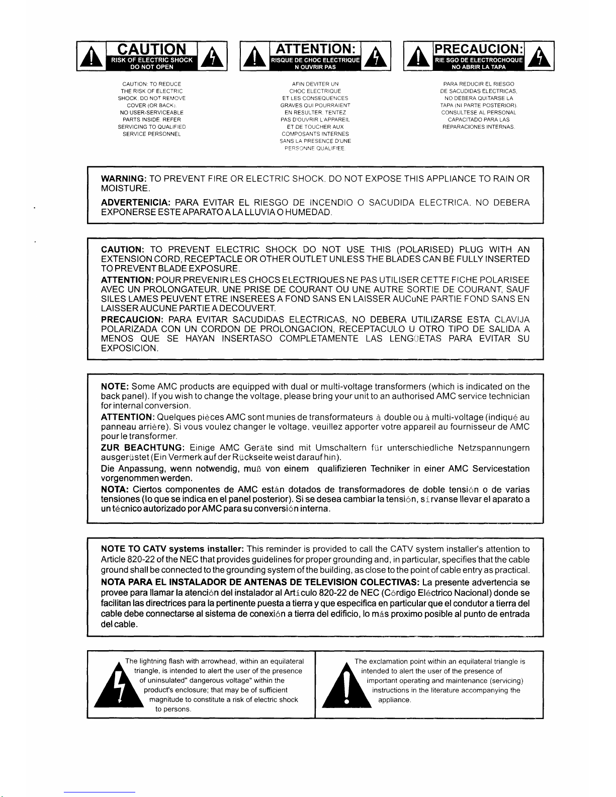
WARNING: TO
PREVENT FIRE
OR ELECTRIC SHOCK. DO NOT EXPOSE THIS APPLIANCE TO RAIN
OR
MOISTURE.
ADVERTENICIA:
PARA
EVITAR EL RIESGO
DE INCENDIO O
SACUDIDA
ELECTRICA. NO DEBERA
EXPONERSE
ESTE APARATO A LA
LLUVIA
O
HUMEDAD.
CAUTION:
TO PREVENT ELECTRIC SHOCK DO NOT
USE
THIS
(POLARISED)
PLUG WITH
AN
EXTENSION CORD,
RECEPTACLE
OR
OTHER OUTLET
UNLESS
THE BLADES
CAN
BE FULLY INSERTED
TO PREVENT
BLADE
EXPOSURE.
ATTENTION: POUR
PREVENIR
LES CHOCS
ELECTRIQUES NE PAS
UTILISER CETTE
FICHE
POLARISEE
AVEC UN
PROLONGATEUR.
UNE
PRISE DE
COURANT
OU
UNE
AUTRE SORTIE DE COURANT, SAUF
SILES
LAMES PEUVENT ETRE INSEREES A
FOND
SANS
EN
LAISSER AUCuNE PARTIE
FOND
SANS EN
LAISSER
AUCUNE PARTIE A DECOUVERT.
PRECAUCION:
PARA EVITAR
SACUDIDAS
ELECTRICAS, NO DEBERA UTILIZARSE ESTA
CLAVIJA
POLARIZADA CON UN
CORDON
DE
PROLONGACION, RECEPTACULO
U OTRO TIPO DE SALIDA A
MENOS
QUE
SE
HAYAN
INSERTASO
COMPLETAMENTE
LAS LENGUETAS PARA
EVITAR SU
EXPOSICION.
NOTE: Some
AMC
products
are equipped with dual or multi-voltage transformers
(which
is indicated
on
the
back
panel).
lf
you
wish to
change
the voltage,
please
bring
your
unit
to an
authorised
AMC service technician
for internal conversion.
ATTENTION:
Quelques
pieces
AMC sont
munies
de
transformateurs
d
double
ou d multi-voltage
(indiqu6
au
panneau
arridre). Si
vous voulez changer le voltage, veuillez
apporter votre appareil au fournisseur de
AMC
pour
le
transformer.
ZUR BEACHTUNG: Einige AMC Gerate sind mit Umschaltern fiir unterschiedliche Netzspannungern
ausgerustet
(Ein
Vermerk
auf
der Ruckseite weist
darauf
hin).
Die Anpassung, wenn notwendig, mu8 von einem
qualifizieren
Techniker in
einer
AMC
Servicestation
vorgenommen werden.
NOTA: Ciertos componentes
de
AMC
est6n dotados de
transformadores
de doble tensi6n o de varias
tensiones
(lo
que
se
indica en
el
panel posterior).
Si se desea cambiar
la tensi6n,
sirvanse
llevar
el aparato
a
un
t6cnico
autorizado
porAMC
para
su conversi6n
interna.
NOTE TO CATV systems installer: This
reminder
is
provided
to
call the CATV
system
installer's
attention to
Article
820-22
of the
NEC that
provides
guidelines
for
proper
grounding
and,
in
particular,
specifies that the
cable
ground
shall be
connected
to
the
grounding
system of the building,
as
close to the
point
of cable entry as
practical.
NOTA PARA EL INSTALADOR
DE ANTENAS DE TELEVISION COLECTIVAS:
La
presente
advertencia
se
provee para
llamar la atenci6n
del
instaladoralArticuloS20-22
de
NEC
(C6rdigo
El6ctrico Nacional)donde
se
facilitan
las directrices
para
la
pertinente
puesta
a tierra
y que
especifica
en
particular que
el condutor a
tierra
del
cable debe connectarse al sistema de conexi6n a tierra del
edificio,
lo mAs
proximo posible
al
punto
de
entrada
delcable.
^
The lightning flash with
arrowhead, within an
equilateral
A
tria-ngle, is
intended
to alert the user
of
the
presence
| ^
of rlninsulated" dangerous voltage"
within the
L ),
product's
enclosure;
that
may be
of
sufficient
Il
magnitude
to constitute
a risk of electric shock
^-'
to"oersons.
a
The exclamation
point
within an
equilateral
triangle
is
A
intended
to
alert
the
user of
the
presence
of
Al;*il:
ii,T
H: fi ::"ilil:"J:;i;,ff
ill
i:'
Page 3

APPLICATION AND FEATURE
LIST
Features
of
AMC model DAC9
*The
AMC model DAC9 was designed to
meet
professional quality
standards
for Digital
to Analog
signal
conversion.
*The
highest
grade
of components are used throughout
with critical components
selected
for their
sonic
performance.
*Double
sided,
through hole
plated,
Printed Circuit
Board for DAC
sections.
*The
AMC
model
DAC9
provides
2
selectable
S/PDIF input,
one
coaxial and one
fiber
optic.
*The
DAC9
can automatically
lock to
either
32KH2,44.1 KHzor 43KHzdigital sampling
rates for
use
with laser
disc
players,
CD's or
DAT machines.
*The
AMC model DAC9
uses
the latest
generation
of bit stream continuous calibration
ultra-linear
Digital
To
Analog Converter, with
inherently low
jitters.
*For
those users
with
digital
recording
capabilities, the
DAC9 has
a digital output
for
connection to DAT, MD
or
DCC type
machines,
thus maintaining the ultimate
in
recording
quality.
*The
AMC DAC9
provides
an accurately calibrated output level
in
accordance
with
the
EIA
(Electronic
Industries Association) recommended
standard of
2 volts. This
output
level
provides
the best
possible performance particularly
for home
theater users.
*The
fiber
optic
input
provides
electrical
isolation from Laser Disc
players,
thereby
avoiding conducted
interference from Video
sources
into
the
Audio
chain.
*The
superior
performance
of the
DAC9 will
provide
not only
improved
technical
specifications
to
your
system,
it will
also significantly upgrade
its
sonic
qualities.
*The
DAC9
can be easily upgraded with
MD5404u1
that
provides yoursystem
with soft
and smooth vacuum tube
sound.
(To
upgrade
with MD5404u1,
please
contact
with
AMC
distributor/dealers in
your
country for more information.
)
2
Page 4

REAR PANEL
CONNECTIONS/FRONT PANEL
CONTROLS
REAR PANEL
-AVrs I
I
nrsoue
oe cnoc
I
I
ELECTRIOUE.
I
(
NE PAS
ouvRrR
J
@
O
"':i'j'
,A\
K)
\E/
;;
O
EO
.o^
o
Allllc o,n ,"
rc Anaros
converter
DAcg
WELTRONICS
CORP.
!C\Da\
.
a
ffi
C(
1. AC LINE
CORD
2.
DIGITAL INPUTS:
LD.DSS
FRONT PANEL
3.
DIGITAL
OUT
4.
AUDIO
OUTPUT
4.'EQ' INDICATOR
5.'SCMS' INDICATOR
6.'32"', 44.1"', 48', I N D I
CATOR
1. POWER
SWITCH AND POWER
INDICATOR
2. INPUT
SELECTOR
SWITCH
3.'LOCKED' INDICATOR
oooooo
Page 5
REAR
PANEL
CONNECTIONS
1. AC
LINE
CORD
Plug
the
AC line
cord
into a nearby wall
outlet that
provides
the
correct
AC
power
line voltage,
or
into
an
un-switched
convenience outlet on
any AMC
product.
2. DIGITAL INPUTS: LD,
DSS
These inputs
are
for
connection to Digital
signal sources
via
one
Toslink fiber
optical
jack
for
LD
and one
RCA
jack
for
DSS.
All
these
inputs
will accept any digital
signal
between 32
and 48kHz
3.
DIGITAL
OUTPUT:
DIGITAL
OUT
This
digital
output is for
digital
recording
via
BNC
terminal,
to allow
onward
connection
to
another digital component
(Such
as a
DAT, DCC, Mini
Disc
or
other
digital
recorder).
4. AUDIO OUTPUT
These L & R
stereo audio outputs are the
outputs of
the Digital to Analog
Converter.
Connect these
outputs to any
input
on
your
amplifier except
"phone"
or
"turntable",
using a high
quality
interconnection
cable.
4
Page 6

FRONT PANEL
CONTROLS
1. POWER
SWITCH
The DAC9 is
turned on
by
depressing the
power
switch.
The
small
indicator
above
the switch will
glow green.
2, INPUT
SELECTOR SWITCH
The rotary
switch selects which digital
input
source
(LD,
DSS) is
fed
to
the
input
of the
DAC.
3.'LOCKED'
INDICATOR
When illuminated
this
indicates
that the
selected digital
input is
being
processed
in
the
Digital
to
Analog
Converter and
is
'locked'
in. lf the
'locked'
light
dose not
illuminate
then
there
is
no
digital
information
being
received.
Check
your
source
and connectors to
trace the
fault.
Please note,
oI certain source
components it is necessary to
switch
on
the
digital output.
4.'ECI' INDICATOR
The
'EQ'
light is
illuminated when
the
Digital
Output singal
requires
analog
de-
emphasis.
This
function
is
automatically
handled
by
the
advanced
digital
processing
circuitry.
EQ
is a form
of
noise
reduction
used
in
the
early delay of
digital
recording,
but rarely used today.
5.
'SCMS'INDICATOR
Stands for
'Serial
Copy Management
System', a device
that
is
in built
into
all
pre-
recorded digital
software
(CDs,DCCs
ect.)
to allow
only one digital copy of
the
original
recording to
be
made. The
SCMS indicator
will
illuminate if the
software
source
is'copy
protected'.
6.
'32" ',44.1"
'48'
INDICATOR
When in operation one of these LEDs will
illuminate indicating the frequency
in
kilohertz of
your
selected digital
input. CD
Transports opreate
at
44.1 k1z
and
DCC/DAT
player
at
anything
between 32
and 48kHz
(depending
on
tape speed and
machine).NlCAM
and
Digital Audio
Broadcasting
(from
satellite) commonly
operate at32kHz. although this
can
vary.
NOTE: Before making copies
of any
pre-
recorded material ensure
you
comply
with
all copyright
restrictions
that may
apply.
5
Page 7
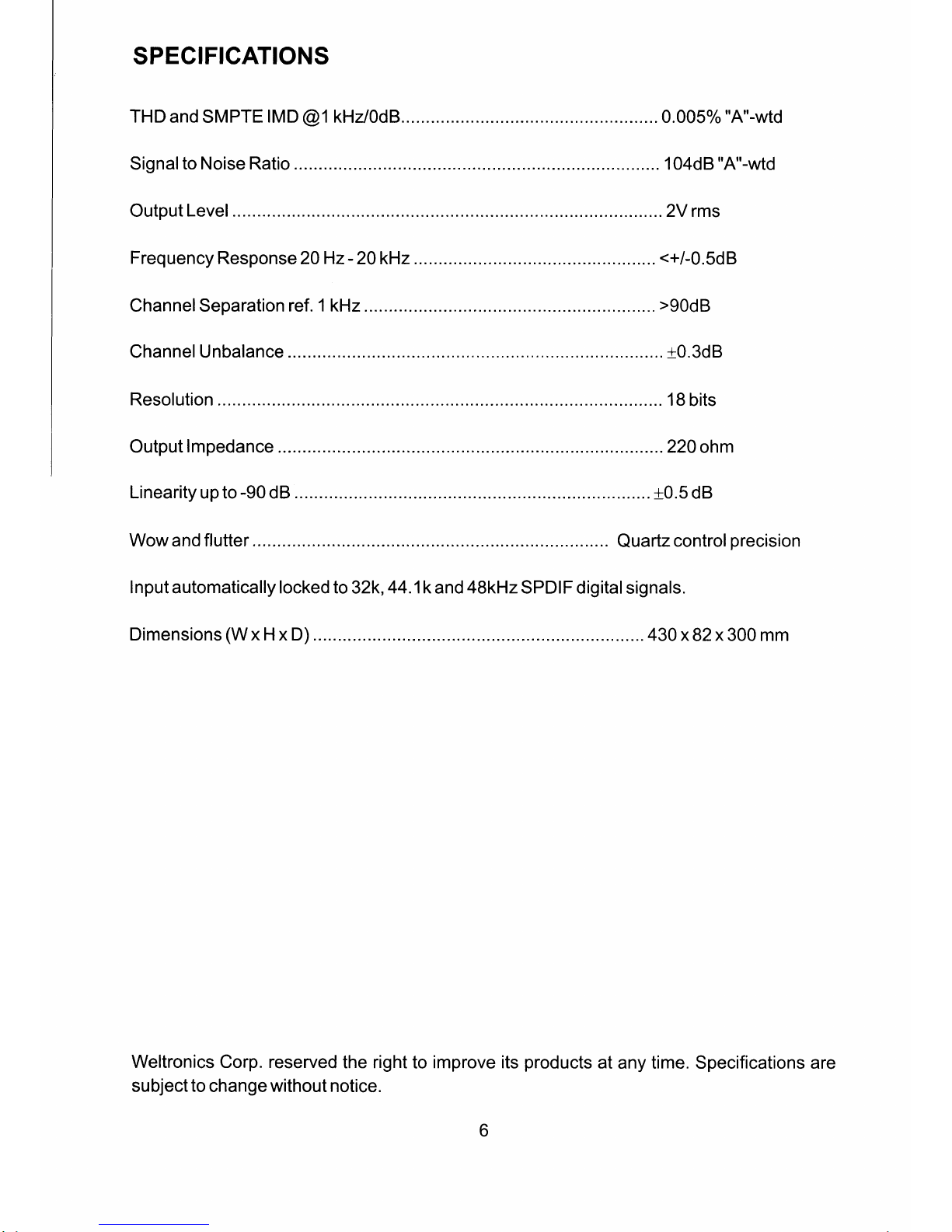
SPECIFICATIONS
THD
and SMPTE
IMD
@1
kHz/OdB.
.. 0.005%
"A"-wtd
Signal
to
Noise
Ratio
....104dB
"A"-wtd
Output
Level
...2V rms
Frequency
Response
20Hz-20kHz
<+/-0.5dB
Channel Separation
ref. 1 kHz
.
".
>90d8
Channel Unbalance
. .....
f0.3dB
Resolution .
.....18
bits
Output
lmpedance
. 220
ohm
Linearity up to
-90
dB
..
t0.5
dB
Wow and flutter..
Quartz
control
precision
Input automatically locked to
32k,
44.1k
and
4SkHzSPDlF
digital
signals.
Dimensions
(W
x H x D)
....
430
x82x 300 mm
Weltronics Corp. reserved
the right
to
improve its
products
at
any time. Specifications are
subject
to
change without notice.
Page 8

SAFETY
INSTRUCTION
1.
READ INSTRUCTIONS.
All
the
safety and
operating instructions should be read before the
appliance is
operated.
2.
RETAIN
INSTRUCTIONS
The
safety and operating instructions should be retained for future
referencs.
3. HEED WARNINGS
All
warnings on
lhe
appliance
and
in
the operating
instructions
should be adhered to.
4.
FOLLOW
INSTRUCTIONS
Alloperating and use
instruptions
should be followed.
5. WATER ANO MOISTURE
The
appliancs
should not
be
used
near
water* for
example, near a
bathtub, washbowl,
kitchen sink,
laundry
tub,
in
a wet basemont, or
n6ar a swimming
pool,
etc.
6.
CARTSANDSTANDS
The
appliance should be usad only with
recommended by the
manufacturer.
6A.
An
appliance and cart combination
should be
moved
with care.
Quick
stops,
excessive lorc€, and uneven surfaces
may
cause the
appliance and
cart
combination
to
overturn.
7. WALL OR CEILING
MOUNTING
This
equipment
is not designed for use mounted on a wall or a
ceiling.
8.
VENTIIATION
The
appliance should be
situated
so that its location
or
position
does
not interfere
with
its
proper
ventilation. For
example, the appliance
should not
be situated
on a bed,
sofa, rug, or similar
surface
that may
block
the
ventilation
openings;
or
placed
in a built-in
installation,
such as bookcase or
cabinet
that may
impede
the flow of air
through
the ventilation openings.
9. HEAT
The appliance
should be
situated away from heal
sources such as
radiators,
heat registers,
stoves, or other
appliances
(including
amplifiers) that
produce
heat.
10. PowER souRcEs
The
appliance
should be connected
to
a
power
supply
only
of
the
type described
in
the operating instructions or as
marked
on
the
appliance.
I1. POWER.CORD PROTECTION
Power-supply
cords should be
routed
so that they are
not
likely to be
walked on or
pinched
by
iterns
placed
upon
or against them,
paying
particular
attention to cords at
plugs,
comvenience
receptacles, and
the
point
whers
they axit from the
appliance.
12. CLEANING
The
appliance
should be
cleaned only
as recommended by the
manufacturer.
!3. NON USE PERIODS
The
power
cord of the appliance should be
unplugged f
rom
the
outlet
when
lett unused
for a long
period
of time.
14.
OBJECT
ANO LIOUIO ENTRY
Care
should
be
taken
so
that
objects do not fall and liquids
are
not
spilled into the
enclosure
through openings.
a cart
or
stand that
is
1s.
SERV|C|NG
The
user should not
attempt
to
service
the
appliance beyond that
described in
the operating
instruc'tions.
All other servicing should be
referred
to
qualified
service
personnel.
16.
DAMAGE
REOUIRING SERVICE
The
appliance should be sqrviced
by
qualified
service
personnel
when:
a) The
power-supply
cord
or
the
plug
has
been damaged;
or
b)
Objects
have
fallen, or liquid has been spilled
into the applianc€;
or
c) The appliance has
been
exposed to
rain;
or
d)
The appliance does
not
app€ar to
operat€
normally or exhibits a
marked change in
performance;
or
e)
The
appliance
has been dropped,
or
the enclosure
damaged.
17.
POWER
LINES
(AppLtEs
ro TUNER AND RECETVERS ONLY)
An outdoor antenna should be
located away
from
power
lines.
I8. OUTDOOR ANTENNA
GFOUNDING
(AppLtEs
To TUNER AND RECETVERS ONLY)
It
an outside
antenna is connected to
the receiver, be
sure
the
antenna system is
grounded
so as to
provide
soms
protection
against
voltage
surges
and
built
u.p static charges.
Section 810
of
the
National Elecirical
Code, ANSI/NFPA
No. 7G19&4,
provides
information with
respect to
proper grounding
of tho mast
and supporting structure,
grounding
of
the
lead-in wire to an antenna
discharge
unit, size of
grounding
conductors,
location
of
antennadischarge unit, connection
to
grounding
electrodes,
and
requirements
tor
the
grounding
electrode.
See
Figure.
a)
Use
No, 10 AwG
(5.3
mm2) cgpper, No. 8 AWG
(8.4mm2)
aluminum, No, 17 AWG
(1.Omm')
copperclad
steel or
bronze
wire, or
larger,
as a
ground
wire.
b)
Secure
antenna lead-in and
ground
wires
to
house with
standotf
insulators spaced from 44
feet
(1
.22-1.83 m) apart.
c)
Mount antenna discharge unit
as close as
possible
to
where lead-in
enters
house.
d)
Use
jumper
wire
not
smaller than No. 6 AWG
(t3.3
mm2)
copper,
or the equivalent, when a
s€parate
antenna-grounding electrode
is
used.
See
NEC
Section 81G210).
Antenna
Grounding
According
to
tfte
National
Electrical
Code
Antenna
Lead
In
Wlre
Anlenna
Orschargc
Unrt
(N€CF
Sectron 8
lO
201
Groundrng
Conductori
(N€C-
Sectron
810.2
ll
Ground
Clamgs
Power
Servrce
Grounctrng
Elecrrode
Systcm
(NEC*
Art
250
Perr
H)
xNatronal
Electrrcal
Code
Avtrlable lrom
Lrbrary
book
Stores. o.
Natronal Frre
Protectron
ASsooatron
lEatterymarch
Park.
Ourncy MA 02269)
7
Page 9

WELTRONIGS
CORP.
LONDON/1.A.
PN:
214047
 Loading...