

Amana W10200890A, W10200891A-SP Installation Instruction
WASHER INSTALLATION INSTRUCTIONS
INSTRUCTIONS POUR L’INSTALLATION DE LA LAVEUSE
Table of Contents Table des matiéres
WASHER SAFETY .........................................................1
INSTALLATION REQUIREMENTS ................................2
Tools and Parts ................................................................2
Location Requirements ..................................................2
Drain System ...................................................................3
Electrical Requirements .................................................4
INSTALLATION INSTRUCTIONS ..................................4
Before you start: remove shipping materials ...............4
Connect Drain Hose ........................................................5
Connect Inlet Hoses ........................................................6
Level Washer ...................................................................7
Complete Installation Checklist .....................................8
INSTALLATION NOTES
Date of purchase: _________________________________
Date of installation: _______________________________
Installer: ________________________________________
Model number: ___________________________________
Serial number: ___________________________________
SÉCURITÉ DE LA LAVEUSE ................................................9
EXIGENCES D’INSTALLATION ................................................. 9
Outillage et pièces .................................................................... 9
Exigences d’emplacement .................................................... 10
Système de vidange ................................................................ 11
Spécications électriques ...................................................... 11
INSTRUCTIONS D’INSTALLATION ........................................ 12
Avant de commencer : retrait du matériel d’expédition ...... 12
Raccordement du tuyau de vidange...................................... 13
Raccordement des tuyaux d’arrivée d’eau ........................... 14
Établissement de l’aplomb de la laveuse .............................. 15
Liste de vérication pour l’achèvement de l’installation ..... 16
NOTES CONCERNANT L’INSTALLATION
Date d’achat: ______________________________________
Date d’installation: __________________________________
Installateur: _______________________________________
Numéro de modéle: _________________________________
Numéro de série: ___________________________________
W10200890A
W10200891A-SP
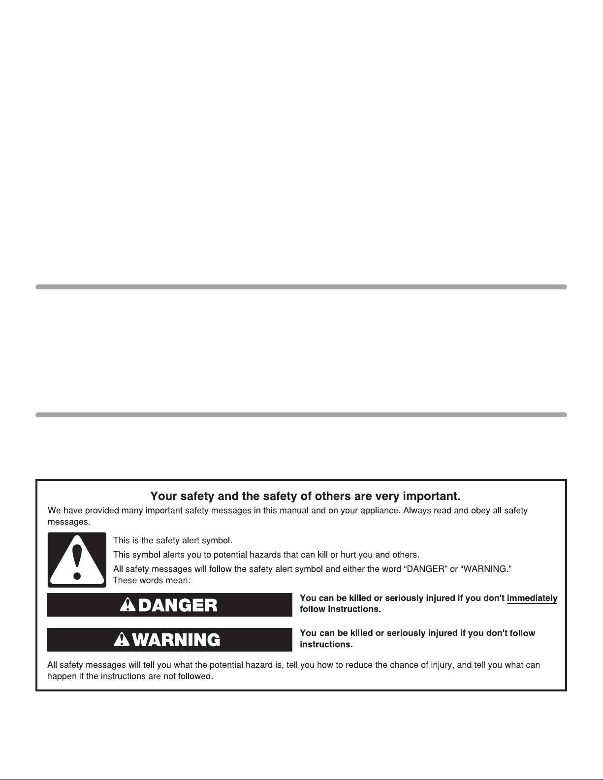
WASHER SAFETY
1
INSTALLATION REQUIREMENTS
27"
(686 mm)
42"
(1067 mm)
25
1
/2"
(648 mm)
4" min
(102 mm)
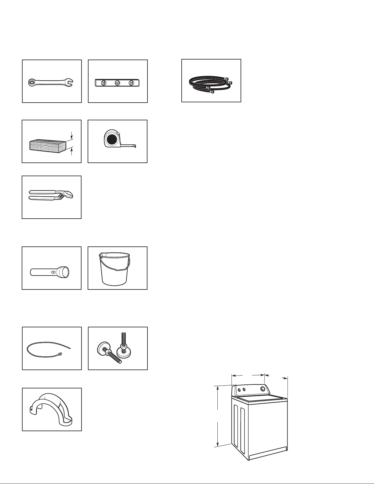
TOOLS AND PARTS
Gather the required tools and parts before starting installation.
Tools needed:
Adjustable or open end
wrench
Wood block
Pliers that open to 19⁄16"
(39.5 mm)
9
/16" (14 mm)
Optional tools:
Level
Ruler or measuring tape
Parts needed: (Not supplied with washer)
Inlet hoses with flat washers
To order, please refer to toll-free phone numbers on front page
of your Washer User Instructions.
n
8212656RP 10 ft. (3.0 m) Inlet hose, Black EPDM (2 pack)
n
8212641RP 5 ft. (1.5 m) Inlet hose, Black EPDM (2 pack)
n
8212646RP 4 ft. (1.2 m) Inlet hose, Black EPDM (2 pack)
n
8212545RP 5 ft. (1.5 m) Inlet hose, Red and Blue EPDM
(2 pack)
n
8212487RP 5 ft. (1.5 m) Nylon braided inlet hose (2 pack)
n
8212638RP 6 ft. (1.8 m) Nylon braided inlet hose, space
saving 90° elbow, hypro-blue steel couplings
(2 pack)
n
8212637RP 6 ft. (1.8 m) Inlet hose, Black EPDM, space
saving 90° elbow, hypro-blue steel couplings
(2 pack)
Alternate parts: (Not supplied with washer)
Your installation may require additional parts. To order, please
refer to toll-free numbers on front page of your Washer User
Instructions.
If you have: You will need:
Overhead sewer Standard 20 gal. (76 L) 39"
(991 mm) tall drain tub or utility
sink, sump pump and connectors
(available from local suppliers)
Flashlight
Bucket
Parts supplied:
NOTE: All parts supplied for installation are in
washer basket.
Beaded Tie Strap
Drain hose form
Front leveling feet with
jam nuts (2)
2
Drain hose too short Kit Part Number 280131
Lint clogged drain Drain protector,
Part Number 367031
LOCATION REQUIREMENTS
Select proper location for your washer to improve performance and
minimize noise and possible “washer walk”. Install your washer in
a basement, laundry room, closet or recessed area.
You will need:
3"
(76 mm)
3"
(76 mm)
24 in.
2
(155 cm2)
48 in.
2
(310 cm2)
19"
(483 mm)
1"
(25 mm)
0"
(0 mm)
4"
(102 mm)
14" max.
(356 mm)
n
A water heater set to 120° F (49° C).
n
A grounded electrical outlet located within 4 ft (0.9 m) of
power
cord on back of washer.
n
Hot and cold water faucets located within 3 ft (0.9 m) of hot
and cold water ll valves on washer, and water pressure of
5-100 psi (34.5-690 kPa).
n
A level oor with maximum slope of 1" (25 mm) under entire
washer. Installing on carpet is not recommended.
n
Floor must support washer’s total weight (with water and
load) of 315 lbs (143 kgs).
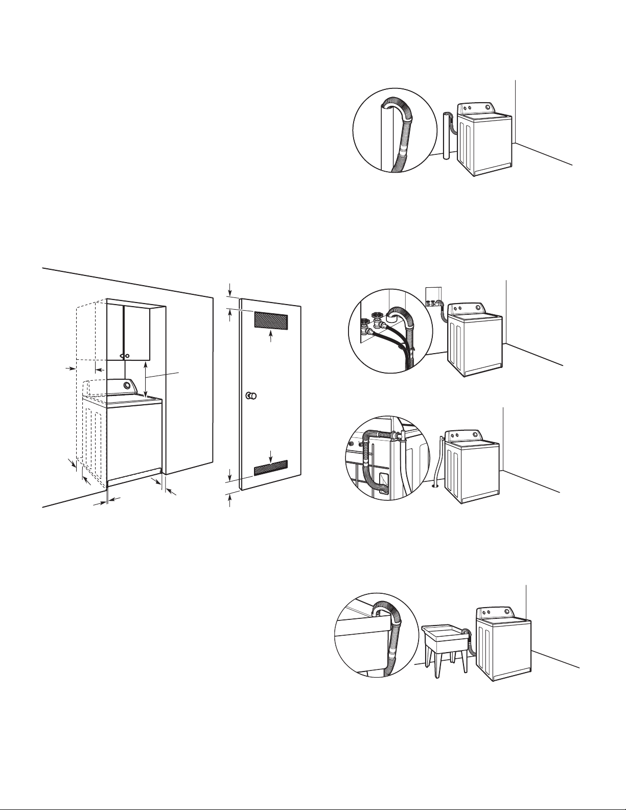
DRAIN SYSTEM
Drain system can be installed using a oor drain, wall standpipe,
oor standpipe, or laundry tub. Select method you need.
IMPORTANT: Do not install, store or operate washer where it
will be exposed to weather or in temperatures below 32° F
(0° C). Water remaining in washer after use may cause
damage in low temperatures. See “Washer Care” in Washer
User Instructions for winterizing information.
Proper installation is your responsibility.
Floor standpipe drain system
Minimum diameter for a standpipe drain: 2" (51 mm).
Minimum carry-away capacity: 17 gal. (64 L) per minute.
1
/4" (6 mm) diameter to 1" (25 mm) diameter Standpipe Adapter
A
Kit is available (Part Number 280130). To order, please see toll-free
phone numbers on front page of your Washer User Instructions.
Top of standpipe must be at least 39" (991 mm) high; install
no higher than 96" ((2.44 m) from bottom of washer. If you
must install higher than 96" (2.44 m), you will need a sump
pump system.
Wall standpipe drain system
See requirements for oor standpipe drain system
Recessed area or closet installation
Dimensions show recommended spacing allowed, except for
closet door ventilation openings which are minimum required.
Consider allowing more space for ease of installation and
servicing; spacing for companion appliances and clearances
for walls, doors and oor moldings. Add spacing of 1" (25 mm)
on all sides of washer to reduce noise transfer. If a closet door
or louvered door is installed, top and bottom air openings in
door are required.
Floor drain system
Floor drain system requires a Siphon Break Kit (Part Number
280129) and additional drain hose (Part Number 3357090)
that may be purchased separately. To order, please see
toll-free phone numbers in your Washer User Instructions.
Minimum siphon break: 28" (711 mm) from bottom of washer.
(Additional hoses might be needed.)
Laundry tub drain system
Minimum capacity: 20 gal. (76 L). Top of laundry tub
must be at least 39" (991 mm) above oor; install no
higher than 96" (2.44 m) from bottom of washer.
IMPORTANT: To avoid siphoning, no more than 8" (203 mm)
of drain hose should be inside standpipe or below the top of
wash tub. Secure drain hose with beaded tie strap.
3
36"
(914 mm)
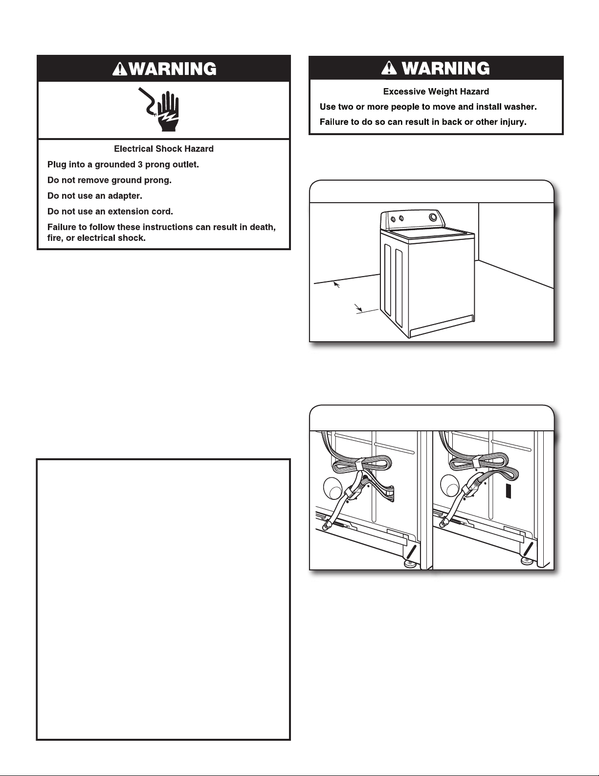
ELECTRICAL REQUIREMENTS
GROUNDING INSTRUCTIONS
For a grounded, cord-connected washer:
This washer must be grounded. In the event of a malfunction
or breakdown, grounding will reduce the risk of electrical
shock by providing a path of least resistance for electric
current. This washer is equipped with a cord having an
equipment-grounding conductor and a grounding plug. The
plug must be plugged into an appropriate outlet that is
properly installed and grounded in accordance with all local
codes and ordinances.
WARNING: Improper connection of the equipment-
grounding conductor can result in a risk of electric shock.
Check with a qualified electrician or serviceman if you are in
doubt as to whether the appliance is properly grounded.
Do not modify the plug provided with the appliance – if it will
not fit the outlet, have a proper outlet installed by a qualified
electrician.
For a permanently connected washer:
This washer must be connected to a grounded metal,
permanent wiring system, or an equipment grounding
conductor must be run with the circuit conductors and
connected to the equipment-grounding terminal or lead on
the appliance.
n
A 120 volt, 60 Hz., AC only, 15- or 20-amp, fused electrical
supply is required. A time-delay fuse or circuit breaker is
recommended. It is recommended that a separate circuit
breaker serving only this waasher be provided.
n
This washer is equipped with a power supply cord having a
3 prong grounding plug.
n
To minimize possible shock hazard, the cord must be
plugged into a mating, 3 prong, grounding-type outlet,
grounded in accordance with local codes and ordinances.
If a mating outlet is not available, it is the personal
responsibility and obligation of the customer to have the
properly grounded outlet installed by a qualied electrician.
n
If codes permit and a separate ground wire is used, it is
recommended that a qualied electrician determine that
the ground path is adequate.
n
Do not ground to a gas pipe.
n
Check with a qualied electrician if you are not sure the
washer is properly grounded.
n
Do not have a fuse in the neutral or ground circuit.
INSTALLATION INSTRUCTIONS
Before you start: remove shipping materials
It is necessary to remove all shipping materials for proper
operation and to avoid excessive noise from washer.
1. Move washer
Move washer to within 3 ft (914 mm) of its nal location, it must
be in a fully upright position.
NOTE: To avoid oor damage, set washer onto cardboard
before moving it.
2. Locate shipping materials
4
Straight power cord Looped power cord
Locate yellow shipping materials on back of washer, near
bottom. If it is a straight power cord and cord restraint, follow
steps 3 & 4 then continue to step 6; if power cord is looped,
skip to step 5.
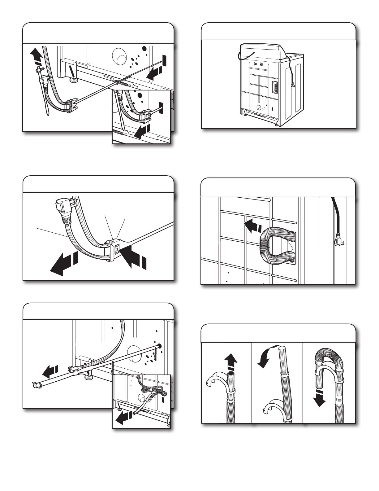
Remove straight power cord
3.
and cord restraint
6. Place power cord over console
Firmly grasp power cord and
pull to completely free power
cord, cord restraint and pin
from rear panel. Pull cord retainer strap out of plug.
NOTE: Remove cotter pin if it did not come free with strap.
4. Remove restraint from power cord
restraint
power cord
Remove restraint from power cord: push power cord in, press
tab and then pull power cord out.
tab
5. Remove looped power cord
Gently place power cord over console to allow free access to
back of washer.
CONNECT DRAIN HOSE
Remove drain hose from washer
7.
cabinet
Gently pull hose out of back of washer cabinet from top until
end emerges.
IMPORTANT: Do not force excess drain hose back into rear
of washer.
Firmly grasp yellow shipping
strap and pull until both ends
are completely removed from
washer.
NOTE: Check that two (2) cotter pins came off with strap.
8. Connect drain hose form
For a laundry tub or standpipe drain, follow steps 8 and 9.
For a oor drain, do not install drain hose form. You may need
additional parts with separate directions. See “Tools and Parts”.
Feed hose into one end of form. Bend hose and feed through
other side, anchoring form on smooth sections of hose.
5
 Loading...