

Page 1
WASHER INSTALLATION INSTRUCTIONS
INSTRUCTIONS POUR L’INSTALLATION DE LA LAVEUSE
Table of Contents Table des matiéres
WASHER SAFETY .........................................................1
INSTALLATION REQUIREMENTS ................................2
Tools and Parts ................................................................2
Location Requirements ..................................................2
Drain System ...................................................................3
Electrical Requirements .................................................4
INSTALLATION INSTRUCTIONS ..................................4
Before you start: remove shipping materials ...............4
Connect Drain Hose ........................................................5
Connect Inlet Hoses ........................................................6
Level Washer ...................................................................7
Complete Installation Checklist .....................................8
INSTALLATION NOTES
Date of purchase: _________________________________
Date of installation: _______________________________
Installer: ________________________________________
Model number: ___________________________________
Serial number: ___________________________________
SÉCURITÉ DE LA LAVEUSE ................................................9
EXIGENCES D’INSTALLATION ................................................. 9
Outillage et pièces .................................................................... 9
Exigences d’emplacement .................................................... 10
Système de vidange ................................................................ 11
Spécications électriques ...................................................... 11
INSTRUCTIONS D’INSTALLATION ........................................ 12
Avant de commencer : retrait du matériel d’expédition ...... 12
Raccordement du tuyau de vidange...................................... 13
Raccordement des tuyaux d’arrivée d’eau ........................... 14
Établissement de l’aplomb de la laveuse .............................. 15
Liste de vérication pour l’achèvement de l’installation ..... 16
NOTES CONCERNANT L’INSTALLATION
Date d’achat: ______________________________________
Date d’installation: __________________________________
Installateur: _______________________________________
Numéro de modéle: _________________________________
Numéro de série: ___________________________________
W10200890A
W10200891A-SP
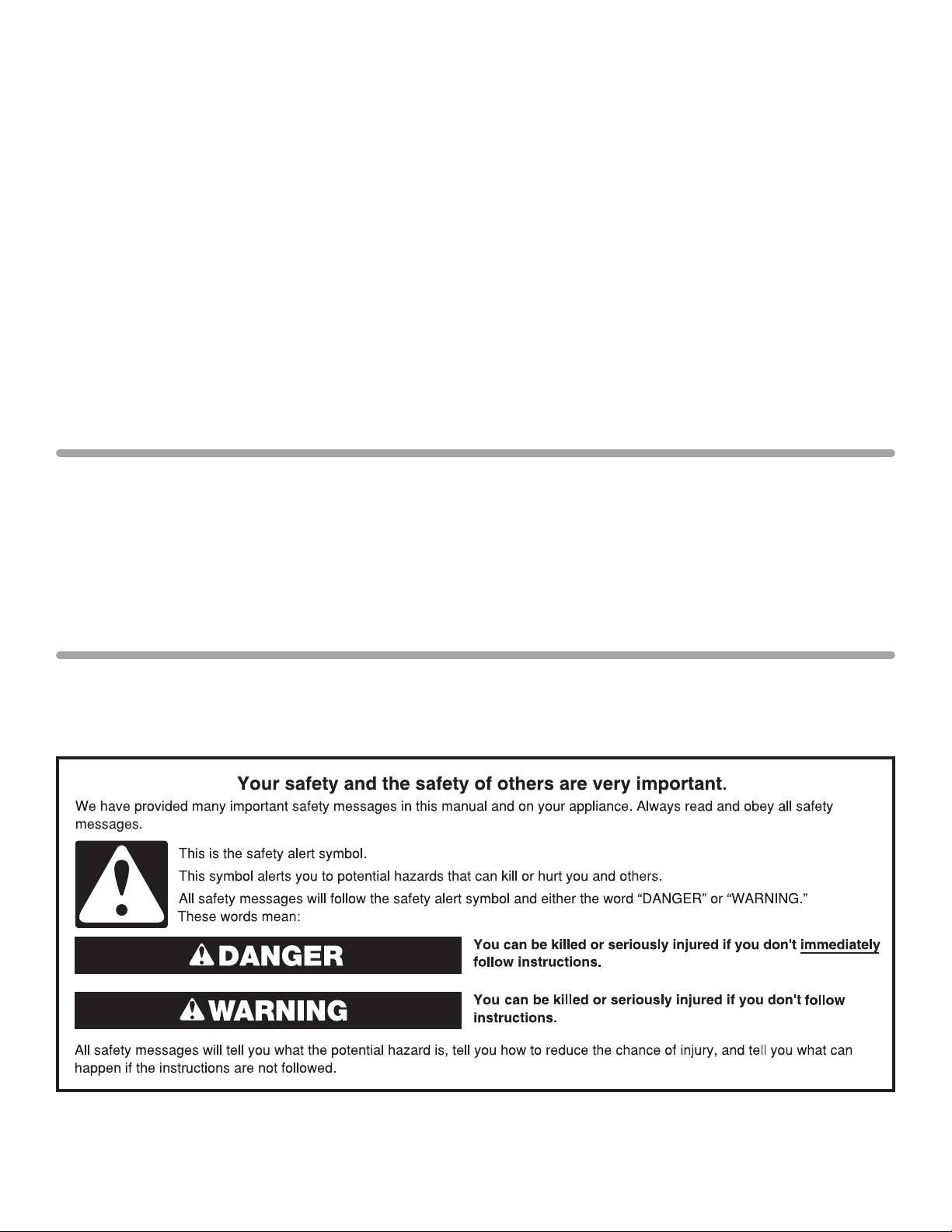
WASHER SAFETY
1
Page 2
INSTALLATION REQUIREMENTS
27"
(686 mm)
42"
(1067 mm)
25
1
/2"
(648 mm)
4" min
(102 mm)
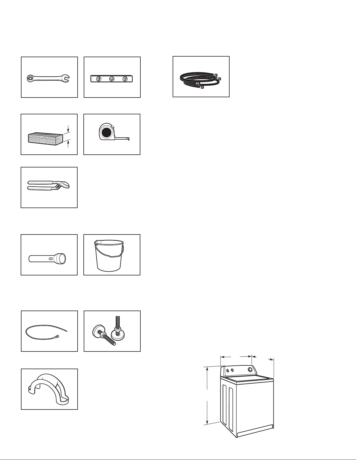
TOOLS AND PARTS
Gather the required tools and parts before starting installation.
Tools needed:
Adjustable or open end
wrench
Wood block
Pliers that open to 19⁄16"
(39.5 mm)
9
/16" (14 mm)
Optional tools:
Level
Ruler or measuring tape
Parts needed: (Not supplied with washer)
Inlet hoses with flat washers
To order, please refer to toll-free phone numbers on front page
of your Washer User Instructions.
n
8212656RP 10 ft. (3.0 m) Inlet hose, Black EPDM (2 pack)
n
8212641RP 5 ft. (1.5 m) Inlet hose, Black EPDM (2 pack)
n
8212646RP 4 ft. (1.2 m) Inlet hose, Black EPDM (2 pack)
n
8212545RP 5 ft. (1.5 m) Inlet hose, Red and Blue EPDM
(2 pack)
n
8212487RP 5 ft. (1.5 m) Nylon braided inlet hose (2 pack)
n
8212638RP 6 ft. (1.8 m) Nylon braided inlet hose, space
saving 90° elbow, hypro-blue steel couplings
(2 pack)
n
8212637RP 6 ft. (1.8 m) Inlet hose, Black EPDM, space
saving 90° elbow, hypro-blue steel couplings
(2 pack)
Alternate parts: (Not supplied with washer)
Your installation may require additional parts. To order, please
refer to toll-free numbers on front page of your Washer User
Instructions.
If you have: You will need:
Overhead sewer Standard 20 gal. (76 L) 39"
(991 mm) tall drain tub or utility
sink, sump pump and connectors
(available from local suppliers)
Flashlight
Bucket
Parts supplied:
NOTE: All parts supplied for installation are in
washer basket.
Beaded Tie Strap
Drain hose form
Front leveling feet with
jam nuts (2)
2
Drain hose too short Kit Part Number 280131
Lint clogged drain Drain protector,
Part Number 367031
LOCATION REQUIREMENTS
Select proper location for your washer to improve performance and
minimize noise and possible “washer walk”. Install your washer in
a basement, laundry room, closet or recessed area.
Page 3
You will need:
3"
(76 mm)
3"
(76 mm)
24 in.
2
(155 cm2)
48 in.
2
(310 cm2)
19"
(483 mm)
1"
(25 mm)
0"
(0 mm)
4"
(102 mm)
14" max.
(356 mm)
n
A water heater set to 120° F (49° C).
n
A grounded electrical outlet located within 4 ft (0.9 m) of
power
cord on back of washer.
n
Hot and cold water faucets located within 3 ft (0.9 m) of hot
and cold water ll valves on washer, and water pressure of
5-100 psi (34.5-690 kPa).
n
A level oor with maximum slope of 1" (25 mm) under entire
washer. Installing on carpet is not recommended.
n
Floor must support washer’s total weight (with water and
load) of 315 lbs (143 kgs).
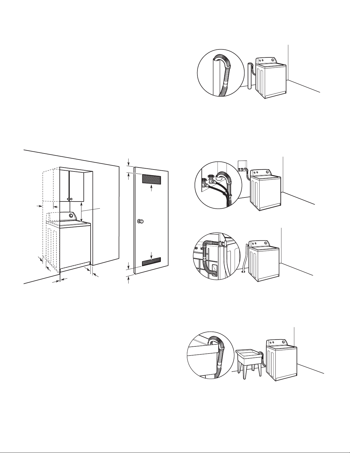
DRAIN SYSTEM
Drain system can be installed using a oor drain, wall standpipe,
oor standpipe, or laundry tub. Select method you need.
IMPORTANT: Do not install, store or operate washer where it
will be exposed to weather or in temperatures below 32° F
(0° C). Water remaining in washer after use may cause
damage in low temperatures. See “Washer Care” in Washer
User Instructions for winterizing information.
Proper installation is your responsibility.
Floor standpipe drain system
Minimum diameter for a standpipe drain: 2" (51 mm).
Minimum carry-away capacity: 17 gal. (64 L) per minute.
1
/4" (6 mm) diameter to 1" (25 mm) diameter Standpipe Adapter
A
Kit is available (Part Number 280130). To order, please see toll-free
phone numbers on front page of your Washer User Instructions.
Top of standpipe must be at least 39" (991 mm) high; install
no higher than 96" ((2.44 m) from bottom of washer. If you
must install higher than 96" (2.44 m), you will need a sump
pump system.
Wall standpipe drain system
See requirements for oor standpipe drain system
Recessed area or closet installation
Dimensions show recommended spacing allowed, except for
closet door ventilation openings which are minimum required.
Consider allowing more space for ease of installation and
servicing; spacing for companion appliances and clearances
for walls, doors and oor moldings. Add spacing of 1" (25 mm)
on all sides of washer to reduce noise transfer. If a closet door
or louvered door is installed, top and bottom air openings in
door are required.
Floor drain system
Floor drain system requires a Siphon Break Kit (Part Number
280129) and additional drain hose (Part Number 3357090)
that may be purchased separately. To order, please see
toll-free phone numbers in your Washer User Instructions.
Minimum siphon break: 28" (711 mm) from bottom of washer.
(Additional hoses might be needed.)
Laundry tub drain system
Minimum capacity: 20 gal. (76 L). Top of laundry tub
must be at least 39" (991 mm) above oor; install no
higher than 96" (2.44 m) from bottom of washer.
IMPORTANT: To avoid siphoning, no more than 8" (203 mm)
of drain hose should be inside standpipe or below the top of
wash tub. Secure drain hose with beaded tie strap.
3
Page 4
36"
(914 mm)
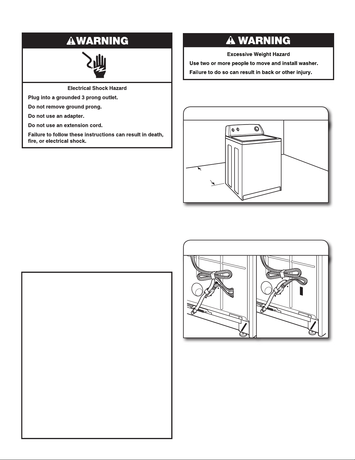
ELECTRICAL REQUIREMENTS
GROUNDING INSTRUCTIONS
For a grounded, cord-connected washer:
This washer must be grounded. In the event of a malfunction
or breakdown, grounding will reduce the risk of electrical
shock by providing a path of least resistance for electric
current. This washer is equipped with a cord having an
equipment-grounding conductor and a grounding plug. The
plug must be plugged into an appropriate outlet that is
properly installed and grounded in accordance with all local
codes and ordinances.
WARNING: Improper connection of the equipment-
grounding conductor can result in a risk of electric shock.
Check with a qualified electrician or serviceman if you are in
doubt as to whether the appliance is properly grounded.
Do not modify the plug provided with the appliance – if it will
not fit the outlet, have a proper outlet installed by a qualified
electrician.
For a permanently connected washer:
This washer must be connected to a grounded metal,
permanent wiring system, or an equipment grounding
conductor must be run with the circuit conductors and
connected to the equipment-grounding terminal or lead on
the appliance.
n
A 120 volt, 60 Hz., AC only, 15- or 20-amp, fused electrical
supply is required. A time-delay fuse or circuit breaker is
recommended. It is recommended that a separate circuit
breaker serving only this waasher be provided.
n
This washer is equipped with a power supply cord having a
3 prong grounding plug.
n
To minimize possible shock hazard, the cord must be
plugged into a mating, 3 prong, grounding-type outlet,
grounded in accordance with local codes and ordinances.
If a mating outlet is not available, it is the personal
responsibility and obligation of the customer to have the
properly grounded outlet installed by a qualied electrician.
n
If codes permit and a separate ground wire is used, it is
recommended that a qualied electrician determine that
the ground path is adequate.
n
Do not ground to a gas pipe.
n
Check with a qualied electrician if you are not sure the
washer is properly grounded.
n
Do not have a fuse in the neutral or ground circuit.
INSTALLATION INSTRUCTIONS
Before you start: remove shipping materials
It is necessary to remove all shipping materials for proper
operation and to avoid excessive noise from washer.
1. Move washer
Move washer to within 3 ft (914 mm) of its nal location, it must
be in a fully upright position.
NOTE: To avoid oor damage, set washer onto cardboard
before moving it.
2. Locate shipping materials
4
Straight power cord Looped power cord
Locate yellow shipping materials on back of washer, near
bottom. If it is a straight power cord and cord restraint, follow
steps 3 & 4 then continue to step 6; if power cord is looped,
skip to step 5.
Page 5
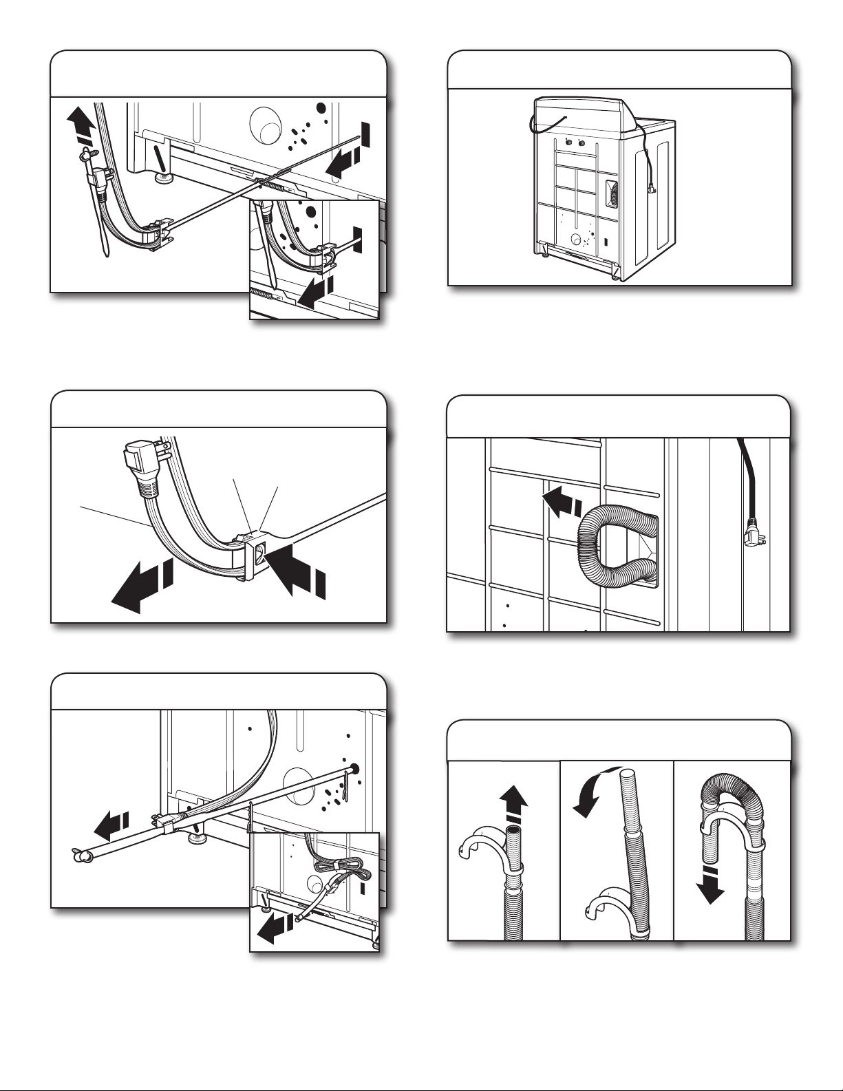
Remove straight power cord
3.
and cord restraint
6. Place power cord over console
Firmly grasp power cord and
pull to completely free power
cord, cord restraint and pin
from rear panel. Pull cord retainer strap out of plug.
NOTE: Remove cotter pin if it did not come free with strap.
4. Remove restraint from power cord
restraint
power cord
Remove restraint from power cord: push power cord in, press
tab and then pull power cord out.
tab
5. Remove looped power cord
Gently place power cord over console to allow free access to
back of washer.
CONNECT DRAIN HOSE
Remove drain hose from washer
7.
cabinet
Gently pull hose out of back of washer cabinet from top until
end emerges.
IMPORTANT: Do not force excess drain hose back into rear
of washer.
Firmly grasp yellow shipping
strap and pull until both ends
are completely removed from
washer.
NOTE: Check that two (2) cotter pins came off with strap.
8. Connect drain hose form
For a laundry tub or standpipe drain, follow steps 8 and 9.
For a oor drain, do not install drain hose form. You may need
additional parts with separate directions. See “Tools and Parts”.
Feed hose into one end of form. Bend hose and feed through
other side, anchoring form on smooth sections of hose.
5
Page 6

9. Place drain hose in standpipe
Place hose into standpipe (shown in picture) or over side of
laundry tub.
IMPORTANT: No more than 8" (203 mm) of drain hose should
be inside standpipe; do not force excess hose into standpipe or
lay on bottom of laundry tub. Drain hose form must be used.
CONNECT INLET HOSES
Washer must be connected to water faucets with new inlet
hoses with at washers (not provided). Do not use old hoses.
11. Clear water lines
Run water for a few seconds through hoses into a laundry tub,
drainpipe or bucket to prevent clogs. Water should run until
clear.
12. Connect inlet hoses to washer
Connect inlet hoses to water
10.
faucets
Attach hose to hot water faucet. Screw on coupling by hand
until it is seated on washer. Use pliers to tighten couplings an
additional two-thirds turn. Repeat this step with second hose
for cold water faucet.
IMPORTANT: Do not overtighten or use tape or sealants on
valve when attaching to faucets or washer. Damage can result.
HELPFUL TIP: Make note of which hose is connected to hot
water to help in attaching hoses to washer correctly.
Attach hot water hose to hot water inlet valve. Screw coupling
by hand until it is snug. Use pliers to tighten couplings an
additional two-thirds turn. Repeat with cold water inlet valve.
IMPORTANT: To reduce risk of hose failure, replace the hoses
every 5 years. Record hose installation or replacement dates for
future reference.
n
If you connect only one water hose, you must cap off
remaining water faucet.
n
Periodically inspect and replace hoses if bulges, kinks, cuts,
wear, or leaks are found.
NOTE: Inlet valves may be arranged vertically or horizontally
depending on your model.
13. Check for leaks
Turn on water faucets to check for leaks. A small amount of
water may enter washer. It will drain later.
6
Page 7

14. Secure drain hose
1"
(25 mm)
Laundry Tub Standpipe Wall
17. Engage rear leveling feet
Secure drain hose to laundry tub leg, drain standpipe or inlet
hoses for wall standpipe with beaded tie strap.
LEVEL WASHER
Leveling your washer properly reduces excess noise and
vibration.
15. Prepare to install leveling feet
Prop up front of washer about 4" (102 mm) with a wood block
or similar object that will support weight of washer. Then screw
locknut onto each foot to within 1" (25 mm) of foot base.
Tilt washer back, remove wood block. Gently lower washer to
oor and slide washer to its nal location. Remove cardboard
used to protect oor. Tilt washer forward, self-adjusting rear feet
will click into place. Gently lower washer to oor.
18. Check levelness of washer
place level here
Place a level on top edges of washer, checking each side
and front. Rock washer back and forth to make sure all four
feet make solid contact with oor. If not level, tip washer and
adjust feet up or down, repeating as necessary.
16. Install front leveling feet
Not Level LEVEL Not Level
Screw feet into threaded holes at front
corners of washer until jam nuts touch washer, but are not tight.
7
Page 8

19. Tighten leveling feet
When washer is level, use a 9/16" or 14 mm open-end or
adjustable wrench to turn jam nuts counterclockwise on feet
tightly against washer cabinet.
HELPFUL TIP: You may want to prop washer again with
wooden block.
COMPLETE INSTALLATION
CHECKLIST
Check electrical requirements. Be sure you have correct
q
electrical supply and recommended grounding method.
Check that all parts are now installed. If there is an extra
q
part, go back through steps to see what was skipped.
Check that you have all of your tools.
q
Check that yellow shipping materials were completely
q
removed from back of washer.
Check that water faucets are on.
q
Check for leaks around faucets and inlet hoses.
q
Remove protective lm from console and any tape
q
remaining on washer.
Check that washer is plugged into a grounded
q
3 prong outlet.
Dispose of/recycle all packaging materials.
q
Read “Washer Use” in your Washer User Instructions.
q
20.
Plug into a grounded
3 prong outlet
To test and clean your washer, measure 1/2 of normal
q
recommended amount of powdered or liquid detergent
and pour it into washer basket or detergent dispenser
(on some models). Close lid. Select any cycle. Start washer
and allow to complete full cycle.
8
Page 9

SÉCURITÉ DE LA LAVEUSE
4" min
(102 mm)
EXIGENCES D’INSTALLATION
OUTILLAGE ET PIÈCES
Rassembler les outils et pièces nécessaires avant
de commancer l’installation.
Outillage nécessaire :
Pièces fournies :
REMARQUE : Toutes les pièces fournies pour
l’installation se trouvent dans le panier de la laveuse.
Adjustable or open end
wrench
Cale en bois
Pince avec ouverture jusqu’à
1
9
/16" (14 mm)
9
/16" (39,5 mm)
Outillage facultatif :
Niveau
Règle ou mètre ruban
Attache de xation
perlée
Bride de retenue pour tuyau
de vidange
Pieds de nivellement avant
avec contre-écrous (2)
Lampe de poche
Seau
9
Page 10

Pièces nécessaires : (Non fournies avec la laveuse)
27"
(686 mm)
42"
(1067 mm)
25
1
/2"
(648 mm)
3"
(76 mm)
3"
(76 mm)
24 in.
2
(155 cm2)
48 in.
2
(310 cm2)
19"
(483 mm)
1"
(25 mm)
0"
(0 mm)
4"
(102 mm)
14" max.
(356 mm)
Tuyaux d’arrivée d’eau avec rondelles plates
Pour commander, consulter les numéros d’appel sans frais
gurant sur la page de couverture des Instructions d’utilisation
de la laveuse.
n
8212656RP Tuyau d’arrivée d’eau de 10 pi (3 m), EPDM
noirs (lot de 2)
n
8212641RP Tuyau d’arrivée d’eau de 5 pi (1,5 m), EPDM
noirs (lot de 2)
n
8212646RP Tuyau d’arrivée d’eau de 4 pi (1,2 m), EPDM
noirs (lot de 2)
n
8212545RP Tuyau d’arrivée d’eau de 5 pi (1,5 m), EPDM
rouge et bleu (lot de 2)
n
8212487RP Tuyau d’arrivée en nylon tressé de 5 pi (1,5 m)
(lot de 2)
n
8212638RP Tuyau d’arrivée en nylon tressé de 6 pi (1,8 m),
coude compact de 90°, raccords hypro-blue
en acier (lot de 2)
n
8212637RP Tuyau d’arrivée de 6 pi (1,8 m), EPDM noir,
coude compact de 90°, raccords hypro-blue
en acier (lot de 2)
Il vous faudra :
n
Un chauffe-eau réglé à 120° F (49° C).
n
Une prise électrique reliée à la terre et située à moins de 4 pi
(0,9 m) du cordon d’alimentation situé à l’arrière de la laveuse.
n
Des robinets d’eau chaude et d’eau froide situés à moins
de 3 pi (0,9 m) des électrovannes de remplissage d’eau
chaude et d’eau froide situées sur la laveuse et une pression
d’eau de 5-100 lb/po² (34,5 à 690 kPa).
n
Un plancher de niveau avec une pente maximale de 1"
(25 mm) sous l’ensemble de la laveuse. L’installation sur
de la moquette n’est pas recommandée.
n
Un plancher capable de supporter le poids total de 315 lb
(143 kg) de la laveuse (eau et charge compris).
IMPORTANT : Ne pas installer, remiser ou faire fonctionner la
laveuse à un emplacement où elle sera exposée aux intempéries
ou à des températures inférieures à 32° F (0° C). De l’eau restée
dans la laveuse après utilisation peut causer des dommages
à basse température. Voir “Entretien de la laveuse” dans les
Instructions d’utilisation de la laveuse pour des renseignements
sur l’hivérisation.
C’est à l’utilisateur qu’incombe la responsabilité de réaliser une
installation correcte.
Autres pièces : (Non fournies avec la laveuse)
Il se peut que l’installation nécessite des pièces supplémentaires.
Pour commander, consulter les numéros d’appel sans frais
gurant sur la page de couverture des Instructions d’utilisation
de la laveuse.
Si vous avez : Il vous faudra :
Un égout surélevé Tuyau de vidange standard de 20 gal.
(76 L) de 39" (991 mm) de haut ou
évier de décharge, pompe de puisard
et connecteurs (disponibles chez les
vendeurs de matériel de plomberie
locaux)
Un tuyau de vidange Numéro de pièce de l’ensemble
trop court 280131.
Le système d’évacuation Protecteur de canalisation, pièce
obstrué par de la charpie numéro 367031
EXIGENCES D’EMPLACEMENT
Le choix d’un emplacement approprié pour la laveuse en améliore
le rendement et réduit au minimum le bruit et le “déplacement”
possible de la laveuse. La laveuse peut être installée dans un
sous-sol, une salle de buanderie, un placard ou un encastrement.
Installation dans un encastrement ou un placard
Les dimensions représentent les dégagements recommandés
permis, hormis pour les ouvertures de ventilation de la porte du
placard qui correspondent aux dimensions minimales
nécessaires. On peut éventuellement laisser davantage de
dégagement pour faciliter l’installation et l’entretien; des
distances de séparation pour les appareils ménagers voisins et
des dégagements pour les murs, portes et plinthes. Ajouter un
espace supplémentaire de 1" (25 mm) de tous les côtés de la
laveuse pour réduire le transfert de bruit. Si l’on installe une
porte de placard ou une porte à persiennes, des ouvertures
d’aération au sommet et au bas de la porte sont nécessaires.
10
Page 11

SYSTÈME DE VIDANGE
Le système de vidange de la laveuse peut être installé à l’aide
d’un conduit d’évacuation au plancher, un tuyau de rejet à l’égout
au plancher ou mural ou un évier de buanderie. Sélectionner la
méthode à utiliser.
Système de vidange avec tuyau de rejet à l’égout
au plancher
Diamètre minimal pour un tuyau de rejet à l’égout : 2" (51 mm).
Capacité minimale d’acheminement : 17 gal. (64 L) par minute.
Un ensemble d’adaptateur de tuyau de rejet à l’égout de 1/4"
(6 mm) à 1" (25 mm) de diamètre est disponible (pièce numéro
280130). Pour commander, consulter les numéros d’appel sans
frais gurant sur la page de couverture des Instructions
d’utilisation de la laveuse. Le sommet du tuyau de rejet à l’égout
doit avoir une hauteur d’au moins 39" (991 mm); ne pas l’installer
à plus de 96" (2,44 m) du fond de la laveuse. Si on doit l’installer
à plus de 96" (2,44 m) de hauteur, un système de pompe
de puisard est nécessaire.
Système de vidange dans un évier de buanderie
Capacité minimale : 20 gal. (76 L). Le sommet de l’évier de
buanderie doit se trouver à au moins 39" (991 mm) du plancher;
ne pas l’installer à plus de 96" (2,44 m) du fond de la laveuse.
IMPORTANT: Pour éviter un effet de siphon, ne pas introduire
plus de 8" (203 mm) de tuyau de vidange à l’intérieur du tuyau
de rejet à l’égout ou sous la partie supérieure de la cuve
de lavage. Immobiliser le tuyau de vidange avec l’attache
de xation perlée.
SPÉCIFICATIONS ÉLECTRIQUES
Système de vidange avec tuyau de rejet à l’égout mural
Voir les exigences pour le système de vidange avec tuyau
de rejet à l’égout au plancher.
Système de vidange au plancher
Le système de vidange au plancher nécessite un ensemble de
brise-siphon (pièce numéro 280129) et un tuyau de vidange
supplémentaire (pièce numéro 3357090) qui peuvent être
achetés séparément. Pour commander, consulter les numéros
d’appel sans frais gurant dans les Instructions d’utilisation
de la laveuse. Dimension minimale pour le brise-siphon : 28"
(711 mm) à partir du fond de la laveuse. (Des tuyaux
supplémentaires peuvent être requis).
n
Une alimentation de 120 volts, 60 Hz, CA seulement, de 15
ou 20 ampères, protégée par un fusible est requise. On
recommande l’emploi d’un fusible ou d’un disjoncteur
temporisé. Il est recommandé de raccorder l’appareil sur un
circuit distinct exclusif à cette laveuse.
n
Cette laveuse comporte un cordon d’alimentation électrique
à trois broches pour liaison à la terre.
n
Pour minimiser les risques de choc électrique, on
doit brancher le cordon sur une prise de courant de
conguration correspondante, à 3 alvéoles, reliée à la terre
et installée conformément aux codes et règlements locaux.
Si une prise de courant de conguration correspondante
n’est pas disponible, le client a la responsabilité et l’obligation
de faire installer par un électricien qualié une prise de
courant correctement reliée à la terre.
n
Si les codes le permettent et si l’on utilise un conducteur
distlnct de liaison à la terre, il est recommandé qu’un
électricien qualié vérie la qualité de la liaison à la terre.
n
Ne pas utiliser une tuyauterie de gaz pour le raccordement
à la terre.
n
En cas de doute quant à la qualité de la liaison à la terre
de la laveuse, consulter un électricien qualié.
n
Ne pas installer un fusible dans le conducteur neutre ou
le circuit de liaison à la terre.
11
Page 12

36"
(914 mm)
REMARQUE: Pour éviter d’endommager le plancher, installer
la laveuse sur un carton avant de la déplacer.
2. Repérer l’emplacement du matériel
d’expédition
Cordon d’alimentation droit Cordon d’alimentation en boucle
Repérer l’emplacement du matériel d’expédition jaune situé
à l’arrière de la laveuse, près du fond. S’il s’agit d’un cordon
d’alimentation droit et d’un dispositif d’immobilisation du cordon
d’alimentation, suivre les étapes 3 et 4, puis passer à l’étape 6; s’il
s’agit d’un cordon d’alimentation en boucle, passer à l’étape 5.
INSTRUCTIONS D’INSTALLATION
Avant de commencer : retirer le matériel d’expédition
Il est nécessaire de retirer tout le matériel d’expédition pour un
fonctionnement correct et pour éviter que la laveuse ne fasse
trop de bruit.
1. Déplacer la laveuse
Ôter le cordon d’alimentation droit
3.
et le dispositif d’immobilisation du
cordon d’alimentation.
Saisir fermement le cordon
d’alimentation et tirer pour le dégager
complètement ainsi que le dispositif
d’immobilisation et la broche du panneau arrière.
Ôter l’attache de retenue du cordon d’alimentation hors de
la prise.
REMARQUE: Ôter la goupille si elle n’a pas été dégagée en
même temps que l’attache.
Déplacer la laveuse à moins de 3 pi (914 mm) de son
emplacement nal, elle doit être en position complètement
verticale.
12
Page 13

4. Retirer l’attache du cordon
d’alimentation
attache
onglet
cordon
d’alimentation
Pour retirer l’attache du cordon d’alimentation : enfoncer le
cordon d’alimentation, appuyer sur l’onglet, puis extraire le
cordon d’alimentation.
5. Retirer le cordon d’alimentation en
boucle
RACCORDEMENT DU TUYAU
DE VIDANGE
Libérer le tuyau de vidange de la
7.
caisse de la laveuse
Extraire délicatement le tuyau de l’arrière de la caisse de la
laveuse à partir du sommet jusqu’à ce que le bout apparaisse.
IMPORTANT: Ne pas forcer l’excédent du tuyau de vidange
dans l’arrière de la laveuse.
8. Raccorder la bride de retenue pour
tuyau de vidange
Saisir fermement la sangle
d’expédition jaune et tirer jusqu’à
ce que les deux extrémités soient
complètement dégagées de la
REMARQUE: Vérier que deux (2) goupilles ont été retirées
avec la sangle.
laveuse.
6. Placer le cordon d’alimentation par
dessus la console
Placer délicatement le cordon d’alimentation par dessus la
console pour permettre le libre accès à l’arrière de la laveuse.
Pour un évier de buanderie ou un tuyau de rejet à l’égout, suivre
les étapes 8 et 9. Pour un conduit d’évacuation au plancher, ne
pas installer de bride de retenue pour tuyau de vidange. Des
pièces supplémentaires avec des directives distinctes seront
peut-être nécessaires. Voir “Outillage et pièces”.
Insérer le tuyau dans l’une des extrémités de la bride de retenue,
plier le tuyau et continuer d’insérer le tuyau jusqu’à l’autre côté
tout en xant la bride de retenue aux sections lisses du tuyau.
13
Page 14

9. Placer le tuyau de vidange dans le
tuyau de rejet à l’égout
Placer le tuyau dans le tuyau de rejet à l’égout (illustré sur
l’image) ou par-dessus le côté de l’évier de buanderie.
IMPORTANT: Il ne doit pas y avoir plus de 8" (203 mm) de
tuyau de vidange à l’intérieur du tuyau de rejet à l’égout; ne pas
forcer l’excédent de tuyau dans le tuyau de rejet à l’égout ni
le placer dans l’évier de buanderie. On doit utiliser la bride de
retenue pour tuyau de vidange.
RACCORDEMENT DES TUYAUX
D’ARRIVÉE D’EAU
La laveuse doit être raccordée aux robinets à l’aide de tuyaux
d’arrivée d’eau neufs dotés de rondelles plates (non compris).
Ne pas utiliser de tuyaux usagés.
11. Purger les canalisations d’eau
Faire couler l’eau par les tuyaux dans l’évier de buanderie, le
tuyau de rejet à l’égout ou le seau pendant quelques secondes
pour éviter toute obstruction. On doit laisser couler l’eau jusqu’
à ce qu’elle soit limpide.
12. Raccorder les tuyaux d’arrivée
d’eau à la laveuse.
Raccorder les tuyaux d’arrivée
10.
d’eau aux robinets.
Fixer le tuyau au robinet d’eau chaude. Visser le raccord à la
main pour qu’il repose sur la rondelle. Serrer les raccords de
deux tiers de tour supplémentaires à l’aide d’une pince. Répéter
cette étape avec le deuxième tuyau pour le robinet d’eau froide.
IMPORTANT: Ne pas serrer excessivement ni utiliser de
ruban adhésif ou de dispositif d’étanchéité sur la valve lors
de la xation aux robinets ou à la laveuse. Cela pourrait
entraîner des dommages.
CONSEIL UTILE: Repérer quel tuyau est raccordé à l’eau
chaude pour permettre une xation correcte des tuyaux
à la machine.
Fixer le tuyau d’eau chaude au robinet d’arrivée d’eau chaude.
Visser le raccord à la main jusqu’à ce qu’il soit bien serré. Serrer
les raccords de deux tiers de tour supplémentaires à l’aide d’une
pince. Répéter pour le robinet d’eau froide.
IMPORTANT: Pour réduire le risque de défaillance des tuyaux,
remplacer les tuyaux tous les 5 ans. Inscrire la date d’installation
ou de remplacement des tuyaux pour référence ultérieure.
n
En cas de raccordement d’un seul tuyau, il faut boucher le
robinet d’eau restant.
n
Inspecter périodiquement les tuyaux et les remplacer en cas
de renement, de déformation, de coupure, d’usure ou si une
fuite se manifeste.
REMARQUE: Les robinets d’arrivée d’eau peuvent être
installés verticalement ou horizontalement selon le modèle.
13. Rechercher les fuites éventuelles
14
Ouvrir les robinets d’eau pour vérier qu’il n’y a pas de fuite. Une
petite quantité d’eau peut entrer dans la laveuse. Elle s’évacuera
plus tard.
Page 15

14. Immobiliser le tuyau de vidange
1"
(25 mm)
Évier de buanderie Tuyau de rejet a
l’égout
Fixer le tuyau de vidange au pied de l’évier de buanderie, au
tuyau de rejet à l’égout ou aux tuyaux d’arrivée d’eau pour le
tuyau de rejet à l’égout mural avec l’attache de xation perlée.
ÉTABLISSEMENT DE L’APLOMB
DE LA LAVEUSE
L’établissement correct de l’aplomb de la laveuse permet de
réduire les nuisances sonores et de limiter les vibrations.
Mur
15. Préparer l’installation des pieds
de nivellement
17. Engager les pieds de nivellement
arrière
Faire basculer la laveuse vers l’arrière, retirer la cale en bois.
Abaisser délicatement la laveuse pour la faire reposer sur le
sol puis la faire glisser jusqu’à son emplacement nal. Ôter
le morceau de carton utilisé pour protéger le plancher. Faire
basculer la laveuse vers l’avant; les pieds auto-réglables arrière
s’emboîteront. Abaisser délicatement la laveuse pour la faire
reposer sur le sol.
18. Contrôler l’aplomb de la laveuse
Soulever l’avant de la laveuse d’environ 4" (102 mm) à l’aide
d’une cale en bois ou d’un objet similaire qui soutiendra le poids
de la laveuse. Visser ensuite le contre-écrou sur chaque pied
jusqu’à moins de 1" (25 mm) de la base du pied.
16. Installer les pieds de nivellement
avant
placer le niveau
à cet endroit
Placer un niveau sur les bords supérieurs de la laveuse en
contrôlant chaque côté et l’avant. Faire bouger la laveuse
d’avant en arrière pour s’assurer que les quatre pieds sont
bien en contact avec le plancher. Si elle n’est pas d’aplomb,
faire basculer la laveuse et régler les pieds vers le haut ou vers
le bas puis recommencer si nécessaire.
Pas d’aplomb APLOMB Pas d’aplomb
Visser les pieds dans les trous letés aux
angles avant de la laveuse, jusqu’à ce que les contre-écrous
soient en contact avec la laveuse mais sans être serrés.
15
Page 16

19. Serrer les pieds de nivellement
LISTE DE VÉRIFICATION
POUR L’ACHÈVEMENT
DE L’INSTALLATION
Consulter les spécications électriques. S’assurer de disposer
q
d’une source d’électricité appropriée et d’une liaison à la terre
conforme à la méthode recommandée.
Vérier que toutes les pièces sont maintenant installées. S’il
q
reste une pièce, passer en revue les différentes étapes pour
découvrir laquelle aurait été oubliée.
Vérier la présence de tous les outils.
q
Lorsque la laveuse est d’aplomb, utiliser une clé plate ou
une clé à molette de 9/16" ou de 14 mm pour tourner les
contre-écrous dans le sens antihoraire sur les pieds, jusqu’à
ce qu’ils soient bien serrés contre la caisse de la laveuse.
CONSEIL UTILE : On devra peut-être de nouveau relever la
laveuse à l’aide d’une cale de bois.
Vérier que tout le matériel d’expédition jaune à été retiré de
q
l’arrière de la laveuse.
Vérier que les robinets d’eau sont ouverts.
q
Vérier qu’il n’y a pas de fuite autour des robinets et des
q
tuyaux d’arrivée d’eau.
Ôter la pellicule protectrice de la console et tout ruban adhésif
q
resté sur la laveuse.
Vérier que la laveuse est branchée sur une prise de courant à
q
3 alvéoles reliée à la terre.
Éliminer/recycler tous les matériaux d’emballage.
q
Lire “Utilisation de la laveuse” dans les Instructions
q
d’installation de la laveuse.
Pour tester et nettoyer la laveuse, mesurer la moitié de la
q
quantité normale recommandée de détergent en poudre
ou liquide et la verser dans le panier de la laveuse ou le
distributeur de détergent (sur certains modèles). Fermer le
couvercle. Sélectionner n’importe quel programme. Mettre
la laveuse en marche et la laisser exécuter un programme
complet.
20.
Brancher sur une prise à 3
alvéoles reliée à la terre.
W10200890A
W10200891A-SP
© 2009 1/09
All rights reserved Printed in U.S.A.
Tous droits réservés. Imprimé aux É.-U.
16
 Loading...