

Page 1
Service
RST and RSS
Gas Ranges
Models and manufacturing numbers
in this manual see page 2A.
Service Manual for
Caloric
®
This manual is to be used by qualified appliance
technicians only. Amana does not assume any
responsibility for property damage or personal injury
for improper service procedures done by an
unqualified person.
RC231002
Revision 3
May 1998
Page 2

INDEX
General Information. ............................................................................................. 3 - 6
Installation Instructions.......................................................................................... 7 - 20
Safe Operating Procedures ................................................................................... 21 - 23
Operation And Service Procedure
Electronic Clock Timer (Slide in Models) ......................................................... 24 - 31
Electronic Range Control (Two Piece Control) ................................................ 32 - 45
Electronic Range Control (One Piece Control) ................................................ 46 - 55
Automatic Electronic Timer .............................................................................. 56 - 59
Cook And Off Clock Timer ............................................................................... 60 - 64
Clock Timer - Mechanical ................................................................................ 65 - 66
Automatic Electronic Timer (Solid State) ......................................................... 67 - 69
Bake And Broil Ignitors, Electric Gas Valve ..................................................... 70
Selector Switch, Oven Thermostat .................................................................. 71
Spark Module, Spark Switch ............................................................................ 72
Door Latch Mechanism, Latch Switch ............................................................. 73
Troubleshooting Guide .......................................................................................... 74 - 84
Disassembly Procedures....................................................................................... 85 - 99
Upper Oven Operation And Service Procedures .................................................. 100 - 106
Wiring Diagrams and Schematics ......................................................................... 107 - 123
REPLACE MANUAL 56397 AND 56074 WITH THIS MANUAL, RC231002.
REV. 1 - ADDED RSS MODELS TO MANUAL.
REV. 2 - ADDED RST382UK, P1141228N; RST388UWW, P1141246N; and RST399UL/W, P1132642N.
RC231002 Rev. 3 2
Page 3

MODEL AND MANUFACTURING NUMBERS
MODEL M/N
RSS307
RSS307-OF
RSS343
RSS352-OF
RSS353-OF
RSS354-OF
RSS355-OF
RSS356UL P1141233N, P1141234N, P1130975N
RSS356UW P1141233N, P1141234N, P1130975N
RSS358UL P1130875N, P1141226N, P1130974N
RSS358UL P1141231N
RSS358ULG P1141218N, P1141226NLG, P1141232N
RSS358ULGCO P1141219N
RSS358UW P1130875N
RSS358UW/L P1141231N
RSS358UWG P1141218N, P1141226NWG, P1141232N
RSS358UWGCO P1141219N
RSS359
RSS359-OF
RSS361
RSS361-OF
RSS363
RSS363-OF
RSS369
RSS369-OF
RSS380
RSS380-OF
RST307
RST308UK P1130723N, P1130725N, P1130727N
RST308UW P1130723N, P1130725N, P1130727N
RST308UL P1130723N, P1130725N, P1130727N
RST308UWW P1130724N, P1130725N
RST308UWW1 P1130726N, P1130728N
RST309
RST354
RST359
RST361
RST362
RST365
RST369
RST376
RST378UL P1141203N
RST378UW P1141203N
RST380
RST381
RST382UK P1141220N, P1141228N
RST387
RST388UWW P1141221N, P1141229N, P1141246N
RST3997UL/W P1132635N, P1132642N, P1132621N, P1132622N
2A RC231002 Rev. 3
Page 4
IMPORTANT INFORMATION
Great pride and workmanship go into every product to provide our Customers with the highest possible quality. We
realize, however, that during its lifetime the product may require service. The information contained in this manual is
intended for use by a qualified service technician who is familiar with the safety procedures required in the repair and
who is equipped with the proper tools and testing instruments.
REPAIRS COVERED IN THIS MANUAL THAT ARE MADE BY UNQUALIFIED PERSONS CAN RESULT IN
HAZARDS DUE TO IMPROPER ASSEMBLY OR ADJUSTMENTS SUBJECTING INEXPERIENCED PERSONS
MAKING SUCH REPAIRS TO THE RISK OF INJURY OR ELECTRICAL SHOCK WHICH CAN BE SERIOUS OR
EVEN FATAL.
IMPORTANT NOTE TO CONSUMER
IF YOU PERFORM SERVICE ON YOUR OWN PRODUCT, YOU MUST ASSUME RESPONSIBILITY FOR ANY
PERSONAL INJURY OR PROPERTY DAMAGE WHICH MAY RESULT. AMANA WILL NOT BE RESPONSIBLE
FOR ANY INJURY OR PROPERTY DAMAGE ARISING FROM IMPROPER SERVICE AND/OR SERVICE
PROCEDURES.
In order to locate an authorized service agency. please consult your telephone book or the dealer from whom you
purchased this product. If you require further assistance, please contact:
CUSTOMER RELATIONS DEPT. OR 1-319-622-5511
AMANA, IOWA 52204 CALL and ask for the
Customer Relations Department
Users of Caloric products outside of the United States and Canada should contact:
EXPORT CUSTOMER RELATIONS DEPARTMENT
AMANA REFRIGERATION, INC.
AMANA, IOWA 52204, USA
TELEX: 4330076 AMANA
CABLE: "AMANA", AMANA, IOWA, USA
RECOGNIZE SAFETY SYMBOLS, WORDS AND LABELS
DANGER - Immediate hazards which WILL result in
severe personal injury or death.
WARNING - Hazards or unsafe practices which COULD
result in severe personal injury or death.
CAUTION - Hazards or unsafe practices which COULD
result in minor personal injury or product or property
damage.
RC231002 Rev. 3 3
Page 5
GENERAL INFORMATION
F
r
e
e
o
V
V
V
GENERAL INFORMATION
This manual provides you with complete instructions and
suggestions for handling, installing, and servicing Caloric
Self-Cleaning Gas Ranges.
This manual is based on information gained through
experience and careful testing. This information, if followed carefully, will assure the customer of proper unit
operation with a minimum of servicing requirements, thus
insuring the maximum benefits of clean, modern cooking.
Unless the unit is properly installed and carefully explained, the customer will not receive the utmost advantages that gas cooking provides.
Feel free at all times, to call Caloric to discuss any
problems which may not be fully understood.
Refer to the Parts Catalog when replacement parts are
needed.
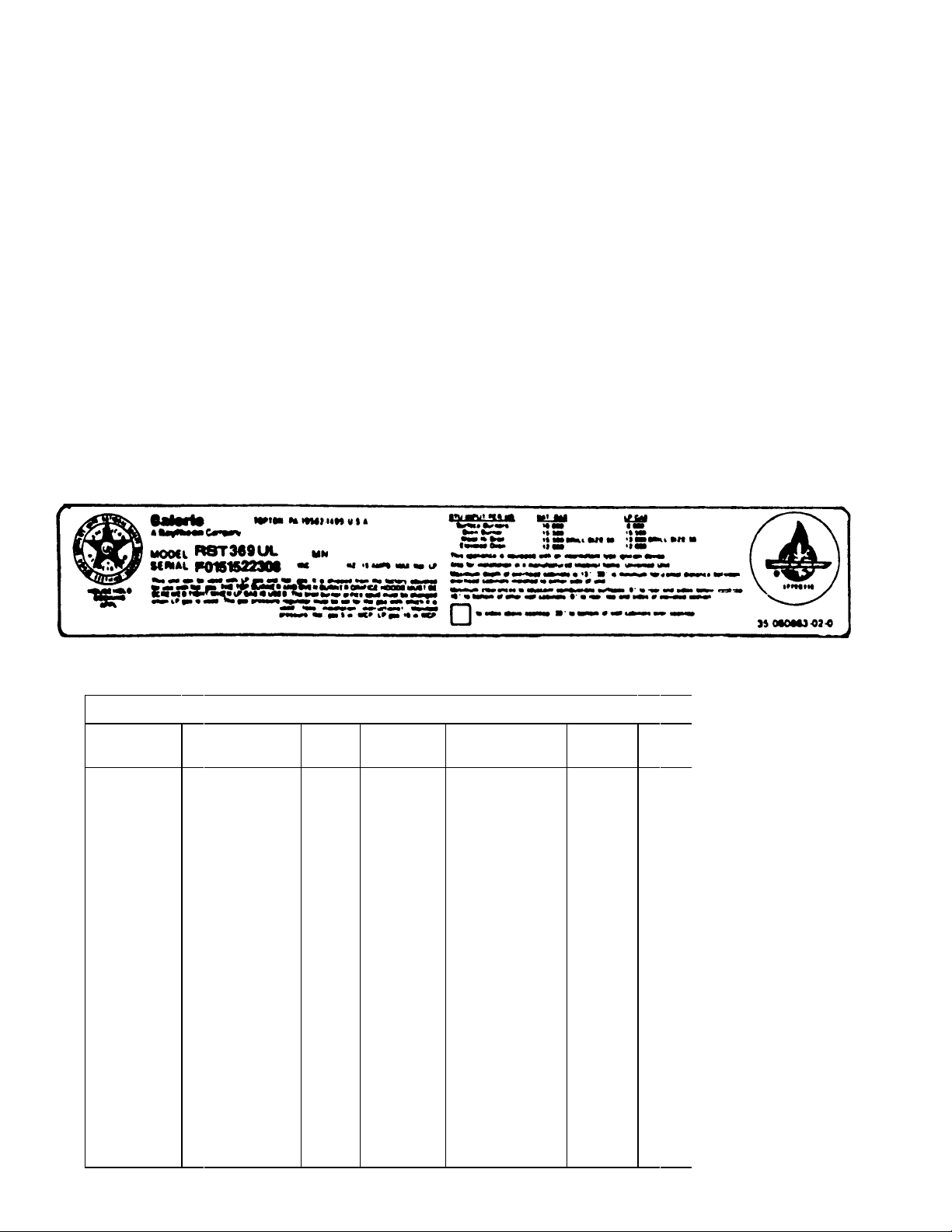
MODEL IDENTIFICATION
The correct model number, manufacturing number (MN or
P), and serial number should be known prior to ordering
parts so that incorrect shipments and delays can be
avoided. (See Rating Label example.)
The rating label is located in the burner box of the unit and
can be observed by raising the main top. The rating label
on sealed burner units is located on the front frame behind
the storage drawer.
The wiring diagram is located on the bottom of the storage
drawer assembly.
E
Electric
R
Gas
T
Trash
Compactor
H
Vent Hood
Microwave
M
CALORIC MODEL DESCRIPTION BREAKDOWN
R S T 3 8 O
PRODUCT
LINE
PRODUCT TYPE SERIES
C
Convertible
H
High Boil
J
Hi-Broil w/ Cont.
Cleaning Panels
Upper Oven
Microwave
K
Lower-Self
Cleaning
Low boil
Low Boil w/
L
Cont. Cleaning
M
Panels
Portable
Self-Clean
P
Cook Top
S
Under-Counter
T
Wall Oven
U
Wall Oven w/
W
Cont. Cleaning
X
Panels
Self-Cleaning
Wall Oven
Y
MicroCombination
R
D
S
T01
2
3
4
6
WIDTH
ON TOP
No Width
Required
15" - 18"
20" - 18"
30" - 35"
40" - 42"
36"
BACKGUARD FEATURE
0
No Backguard
1
Plain Rail/
Laminated Top
Plain Rail/
2
Cutting Board
4" Backguard
3
w/Auto-Timer
Special
4
Designation
Standard
5
Deluxe
6
Backguard
Special
7
Designation
Deluxe
8
Backguard
Double Decker
9
Varible N
Natu
L
Bottl
U
Univ
X
Exp
1
115
2
230
8
208
RC231002 Rev. 3 4
Page 6

GENERAL INFORMATION
RECEIVING
Inspect unit thoroughly at time of delivery. Report any
visible damage to the carrier immediately. If the damage
is "concealed" and not discovered until after delivery has
been accepted, make a "concealed damage report" to the
carrier. "Concealed damage report" forms may be obtained from the carrier's agent.
This procedure must be followed: All shipments, i.e.,
complete range or parts, are shipped at the buyer's risk.
Manufacturer's responsibility ends when the consignment
is accepted by the carrier in "good order". Manufacturer
will give every assistance on damage claims by supplying
any necessary supporting papers, such as invoices or bills
of lading. It must be understood that this assistance does
not imply acceptance of responsibility for settlement of
such claims. Claims for loss or damage cannot be deducted from the invoice or payment of the invoice cannot
be withheld pending adjustment of claims. Do not return
any unit or parts for credit without written consent.
CARE AND HANDLING OF PORCELAIN ENAMEL
1. Porcelain enamel is glass that has been fused onto a
metal surface. Because it is glass, however, it cannot
be guaranteed.
It is impossible to make perfect color match in commercial enamel, and occasional variations must be
expected. Minor imperfections are not just causes for
complaint or rejection.
Porcelain will not stand heavy, sharp blows from
cooking utensils or any other object.
soon as cool enough using dry cloth. If not cleaned,
there may be noticeable smoke, odor, or visible dirt
the next time the unit is used.
3. Crazing - Craze is the name given to the small hair
line marks which are sometimes found in enameled
surfaces after use. They look like little cracks, but
they are not. The enamel around them will never chip
or peel off due to these marks. As we cannot
guarantee enamel against crazing or discoloration,
the customer should be informed as to the proper care
of enamel.
To the customer, any mark is a defect, as they do not
understand enamel. They are afraid the enamel will
peel or crack off leaving a rusty spot. This is not true
as craze marks will never peel or crack. A craze mark
is simply a place where the outer coat of enamel has
separated. The dark color that appears in the crack
is dust that catches in the opening.
To service a craze complaint, it is best to use the
following: Explain crazing to the customer using as
an illustration the effect of hot water in a cold glass it cracks. Compare it to the hairlines in dishes and
cups due to continued heating and cooling. If the
customer can be made to understand that the enamel
will never come off, the customer will be satisfied.
One point to remember with service calls on crazing
is to take care of it immediately. The longer the
customer has to wait, the worse it appears to her.
While this is true of all service work, it is especially
true of crazing complaints. Make it a point to go out
the same day the complaint is received.
In cleaning enamel, soap and water will usually
suffice. Remove any discoloration promptly, but do
not apply cold water to a hot surface.
Fruit juices, vegetable acids, sour milk, or strong
mineral acids may discolor or etch enamel.
2. Cleaning Broiler Pan
For simplest method of cleaning, it is recommended
that broiler pan be submerged in warm water immediately after use. Use a stiff brush, if necessary.
Reheating broiler pan after it has been used without
cleaning will result in fats and greases burning on and
becoming much more difficult to remove.
NOTE: After the food has been removed from the
oven or broiler, and the unit has been turned off, leave
the oven and broiler door open for a few minutes to dry
out the interior. If food has cooked over or grease has
spattered the interior, clean the parts thoroughly as
CARE AND HANDLING OF CHROME, GLASS, OR
METAL FINISH
To keep the stainless, chrome, or glass finishes "looking
new" wash with soap and water, rinse, then dry with a clean
cloth. If a polish is necessary, only the highest quality
chrome cleaning compounds are recommended.
Finger marks and smears may easily be removed with a
mild cleaner such as glass wax and simonize cleaner.
Such agents should be used sparingly. Never use ordinary
steel wool as it may leave a film of iron which will rust and
discolor creating the illusion that the finish is rusting.
Never use harsh, gritty cleaners which can "age" or damage the porcelain and/or polished metal trim.
Never use strong chemical oven cleaners in a self-clean
oven. They are unnecessary and their residues can
produce noxious odors during self-clean, with oven temperatures of 900°F. or more.
5 RC231002 Rev. 3
Page 7

GENERAL INFORMATION
SPECIFICATIONS - Burner Ratings - RST
Non Sealed Nat 10,000 BTU/HR
Top Burner LP 7,000 BTU/HR
Sealed Top Nat 9,000 BTU/HR
Burner LP 7,000 BTU/HR
Cast Sealed RST/RSS
Top Burner
Large (3) Nat 9,000 BTU/HR
LP 8,000 BTU/HR
Small (1) Nat 7,000 BTU/HR
LP 6,000 BTU/HR
Oven Burner Nat 15,500 BTU/HR
Lower LP 15,000 BTU/HR
Broil Nat 15,500 BTU/HR
Burner LP 13,000 BTU/HR
Oven Burner Nat 12,000 BTU/HR
Upper LP 12,000 BTU/HR
BURNER ORIFICE SIZES - Universal Models
SPECIFICATIONS - Burner Ratings - RSS
NON SEALED
Top Burner Nat 10,000 BTU/HR
Top Burner LP 8,000 BTU/HR
Oven Burner Nat 15,5000 BTU/HR
Lower LP 15,500 BTU/HR
Broil Nat 15,500 BTU/HR
Burner LP 13,000 BTU/HR
Non Sealed Top Burners are equipped with #54 double
coaxial orifices and universal pin.
Sealed Top Burners are equipped with a 4-#54 orifice
spud for natural gas and separately packed 4-#68 orifice
spud to convert to LP gas.
or
beginning October 22, 1990 at serial number F0430127550
the venturi type top burners are equipped with #54 double
coaxial orifices and universal pin.
Cast Sealed Top Burners are equipped with 3-#54 double
coaxial orifices with universal pins and 1-#56 double
coaxial orifice with universal pin.
Lower Oven Burner is equipped with a #50 double coaxial
orifice and universal pin.
Broil Burner is equipped with a #54 orifice spud and
separately packed orifice spud to convert to LP gas.
Upper Oven Burner is equipped with a #52 double coaxial
orifice and universal pin.
ELECTRICAL REQUIREMENTS
These ranges should be connected to a separate 115 volt,
60 cycle AC three-wire "U" ground receptacle, parallel
slots.
RC231002 Rev. 3 6
Page 8
INSTALLATION INSTRUCTIONS
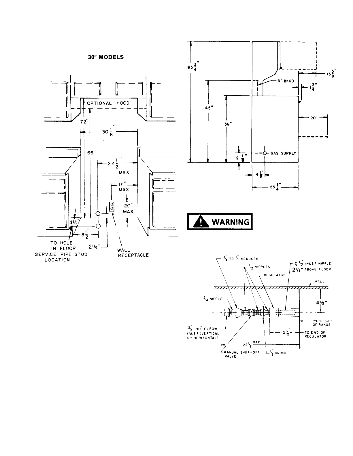
SUGGESTED LOCATION OF SERVICE PIPE - REAR
WALL OR FLOOR
FIGURE 1
UNIVERSAL MODELS (Nat or LP Gas)
The regulator is factory adjusted for natural gas with a
supply line pressure of not less than 6-inches water column
pressure (W.C.P.). With the regulator adjusted for liquefied petroleum (LP) gas, the minimum supply pressure is
11 inches W.C.P. For conversion procedure to LP gas see
the section on regulators and LP conversion procedures.
Cabinet Installation opening for gas slide-in range. See
Page 10.
FIGURE 2
FIRE OR EXPLOSION
HAZARD
THE MAXIMUM GAS SUPPLY PRESSURE FOR THESE
MODELS MUST NOT EXCEED 14-INCHES W.C.P.
Top View
Figure 3
7 RC231002 Rev. 3
Page 9
INSTALLATION INSTRUCTIONS
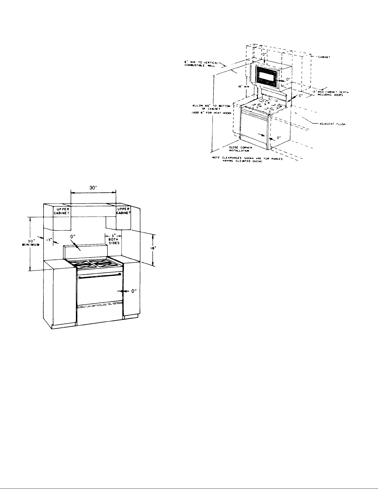
INSTALLATION
Location
The location of the range should be selected so proper
illumination, freedom from drafts, and convenience to
other appliances in the kitchen are obtained. Carefully
level the range, using the leveling legs provided. The
range must be level in order to assure uniform cooking and
baking. A level or a large pan of water placed on an oven
rack or on top of range can be used to level the unit. The
range is to be installed flush to rear wall, and may be
installed flush to side base cabinets. Spacing to vertical
side wall above cooking surface 3" (as shown in Figure 2),
6" (as shown in Figure 3), for ranges with elevated ovens.
Minimum distance to horizontal combustible surface above
cooking surface is 30" and must be the width of the range.
Maximum depth of cabinets installed above the range is
13".
Ranges With Elevated Ovens
Figure 5
It is the responsibility of the installer to comply with the
installation clearances specified on the rating plate
attached to the appliance.
Single Ovens
Figure 4
NOTE: Clearance specified to combustible construction
(walls and materials) are based on a temperature rise of
wood structures resulting from appliance operation. These
clearances are suitable for walls of studding, lath and
plaster, or other types of combustible materials which have
a density of 20 pounds per cubic foot or more. No
evaluation of the clearances required has been made for
installations adjacent to low density cellulose, fiber board,
and similar materials which have a density of less than 20
pounds per cubic foot; nor to plastic tiles, or sheeting.
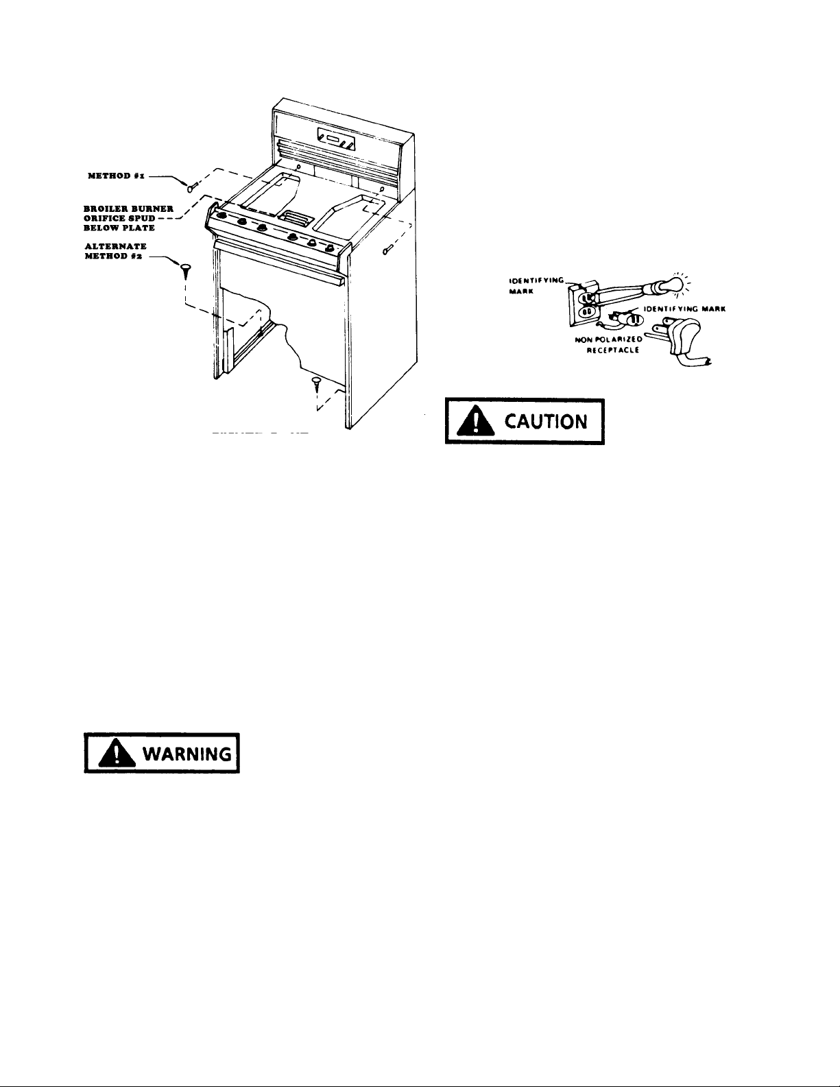
SECURE RANGE TO HOUSE STRUCTURE
For safety consideration means have been provided for
this range, except one having an elevated oven, to be
secured to th house wall behind the range, METHOD 1#
(see Figure 5A). If the wall behind the range is solid wood
or a vertical stud is available, a wood screw or lag bolt of
sufficient length may be employed to secure the range. If
the wall behind the range is not solid such as paneling or
dry wall (sheet rock) construction use of a Molly Bolt is
required. The anchor portion of the Molly Bolt should be of
sufficient lenght to hold it securely to the building material.
The thicker the material, the longer the anchor portion
must be.
RC231002 Rev. 3 8
Page 10
INSTALLATION INSTRUCTIONS
Figure 5A
IN MOBILE HOMES:
Any installtion in a mobile home must conform with the
Manufactured Home Consutruction and Safety Standards.
Title 24CFR, Part 32-80 (in Canada, CSA standard Z240,4-
1) or when such standard is not applicable, with the local
codes.
For mobile home installation it is necessary to use alternate METHOD #2 (see Figure 5A) to secure range to floor.
See rating label to determine if range can be used in this
application.
ANY OPENINGS IN THE WALL BEHIND THE RANGE
OR THE FLOOR UNDER THE RANGE MUST BE SEALED.
Where local codes permit, a TEMPORARY CONNEC-
TION may be made to properly ground a two-prong wall
receptacle by the use of an adaptor which is available at
most local hardware stores.
An adaptor plug can temporarily be used (see Figure 4)
preferably with polarized male blades. If an unpolarized
adaptor plug must be used, determine which is the "hot"
side and ground. Place an identifying mark on the adaptor
to assure proper polarization in the future.
Figure 6
ATTACHING THE ADAPTOR GROUND WIRE TO THE
WALL RECEPTACLE COVER SCREW DOES NOT
GROUND THE APPLIANCE UNLESS THE COVER
SCREW IS GROUNDED THROUGH THE HOUSE
WIRING.
If there is any doubt as to whether the wall receptacle is
properly grounded, the customer should have it checked
by a qualified electrician.
DO NOT, UNDER ANY CIRCUMSTANCES, CUT OR
REMOVE THE THIRD (GROUND) PRONG FROM THE
POWER PLUG.
ELECTRICAL CONNECTIONS
FIRE OR EXPLOSION
HAZARD
FOR GROUNDING - THIS APPLIANCE MUST BE
ELECTRICALLY GROUNDED IN ACCORDANCE WITH
LOCAL CODES, OR, IN THE ABSENCE OF LOCAL
CODES, WITH THE NATIONAL ELECTRIC CODE, ANSI/
NFPA NO. 70-1990. FAILURE TO FOLLOW THESE
INSTRUCTIONS MAY RESULT IN ELECTRIC SHOCK,
PERSONAL INJURY OR DEATH.
The power cord on this appliance is equipped with a threeprong (grounding) plug which mates with standard threeprong (grounding) receptacles.
Where a standard two-prong wall receptacle is encountered, it is the personal responsibility and obligation
of the customer to have it replaced with a properly grounded
three-prong wall receptacle.
9 RC231002 Rev. 3
Page 11
INSTALLATION INSTRUCTIONS
CONNECTING TO GAS SUPPLY LINE
Access to connection is behind bottom storage drawer.
The pressure regulator has a 1/2" female pipe thread. It is
recommended that a 1/2" close nipple, a union and shutoff valve, be assembled into the regulator. This places the
assembly for each connection to the gas supply and access
to the shut-off valve as illustrated in Figure 1.
The gas supply pipe to the range should be 3/4" rigid pipe
then reduced to 1/2" pipe at the pressure regulator. If a long
run of fuel is required, a larger size pipe may be required.
With the liquified petroleum (LP) gases, the size of the
piping or tubing can be 1/2" minimum. LP gas suppliers
usually determine the size and material used on the
system. We do not recommend that flexible connectors be
used in connecting our appliance to the gas supply, unless
American Gas Association approved. Poorly designed
connectors can be a source of gas leak. Even when AGA
approved flexible connectors are used the customer should
be cautioned against kinking or damaging the connector
when moving the range for cleaning or any reason. This
could cause a gas leak.
A shut-off valve should be installed in the line supplying
gas to the range. Check local building codes and utility
requirements. (See Figure 1 for details.)
A suitable pipe thread sealing material should be used,
which is approved for use with LP gases.
Caloric ranges are designed for easy connection between
the supply line and the inlet fitting. However, all strains
must be removed from the supply and fuel lines so the
range will be level and in line.
Use two (2) wrenches when connecting to the regulator.
burner valves should be closed and the gas supply turned
on. All connections in the gas supply line and in the range
should be tested with soap suds for any leaks. If a leak is
present, bubbles will appear. The leak should be corrected
by tightening the joint, or unscrewing it completely and
applying additional dope. Any connections which may
have been disturbed should be tested for leaks.
FIRE OR EXPLOSION
HAZARD
A LIGHTED MATCH OR FLAME SHOULD NEVER BE
USED WHEN TESTING FOR LEAKS. ALL FITTINGS
AND CONNECTIONS HAVE BEEN TIGHTENED AND
TESTED AT THE FACTORY. IF A LEAK IS DETECTED,
TIGHTEN THE FITTING, DO NOT USE PIPE DOPE ON
FACTORY FITTINGS.
The gas supply pipe to the range should be 3/4" rigid pipe
then reduced to 1/2" pipe at the pressure regulator. If a long
run of fuel line is required, a larger size pipe may be
required. With liquefied petroleum (LP) gases, the size of
the piping or tubing can be 1/2" minimum. LP gas suppliers
usually determine the size and material used on the
system. We do not recommend that flexible connectors be
used in connecting our appliance to the gas supply, unless
American Gas Association approved. Poorly designed
connectors can be a source of gas leak. Even when AGA
approved flexible connectors are used the customer should
be cautioned against kinking or damaging the connector
when moving the range for cleaning or any reason. This
could cause a gas leak.
A shut-off valve should be installed in the line supplying
gas to the range. Check local building codes and utility
requirements.
A suitable pipe thread sealing material should be used,
which is approved for use with LP gases.
FIRE OR EXPLOSION HAZARD - LEAK TEST
COMPONENTS AFTER CONNECTION.
THE REGULATOR IS DIE CAST AND WILL CRACK,
RESULTING IN A GAS LEAKAGE AND POSSIBLE FIRE
OR EXPLOSION, IF YOU MAKE THE CONNECTION
TOO TIGHT.
The stack on the regulator must be in vertical position. BE
SURE to use pipe dope to seal connections.
Be sure the shut-off valve is open between the inlet nipple
and gas valve.
TEST FOR GAS LEAKS
After the final gas connection has been made, all the top
RC231002 Rev. 3 10
Caloric ranges are designed for easy connection between
the supply line and the inlet fitting. However, all strains
must be removed from the supply and fuel lines so the
range will be level and in line.
Page 12
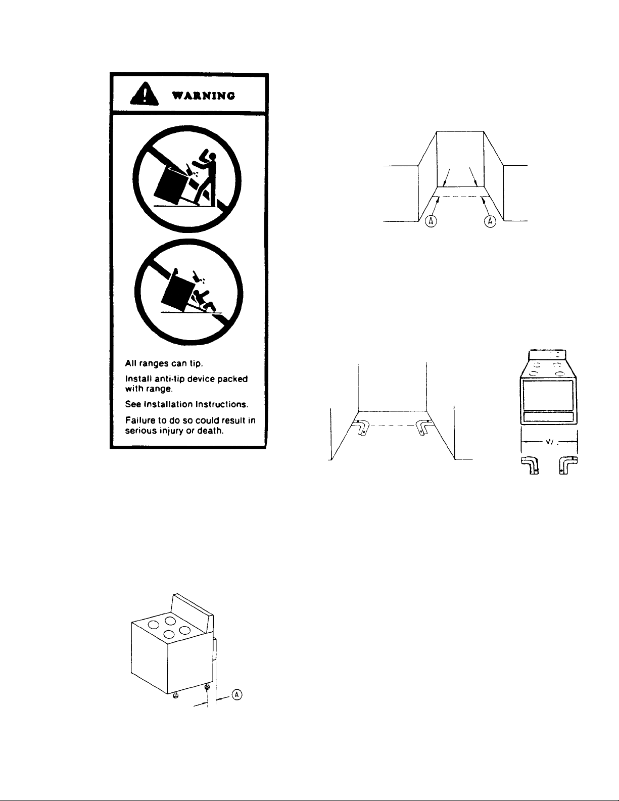
INSTALLATION INSTRUCTIONS
3. From the right rear edge of the prepared cutout,
measure the distance "A" and mark a point. Repeat
this procedure for the left hand side, then draw a
straight line between these points. (See Figure A.)
Figure 8
4. Place the bracket with the inside edge against the
straight line and the end against the cabinet side.
(See Figure C.) If you do not have cabinets on both
sides of the range, it will be necessary to measure the
width of the range (W) and place the bracket at the
appropriate location. (See Figure D.) Mark two (2)
hole locations.
INSTALLATION INSTRUCTIONS FOR ANTI-TIP
BRACKET
To Install Anti-Tip Bracket, Carefully Follow these
Instructions:
1. Prepare counter cutout per range Installation Instructions.
2. Measure the distance from the range leveling leg
shaft to the rear most projection of the range. (See
Figure A). This will be referred to as distance "A".
Figure 7
Figure 9
5. If mounting into wood flooring, drill two (2) 3/32" holes
as marked. If mounting into concrete, using a masonry drill bit, drill two (2) 3/16" holes and insert plastic
anchors. Position bracket and mount using supplied
screws.
6. Turn the leveling legs out approximately 1/4". The
range may now be pushed into position. Remove the
storage drawer and check that the leg has engaged
the mounting bracket. If it has not, the bracket must
be relocated to ensure engagement of the leveling leg
into the bracket. If the range is moved from its original
mounting location, the bracket must be removed and
used for the new mounting location.
Figure 10
11 RC231002 Rev. 3
Page 13
INSTALLATION INSTRUCTIONS
CABINET INSTALLATION OPENING FOR GAS
SLIDE-IN RANGE
A. Cabinet cutout must be prepared as shown in Figure
11. Never install a range over kitchen carpeting.
Figure 11
LO BACK RAIL SLIDE-IN MODEL
B. For electric and gas connection specifications refer to
instructions for installing automatic pilotless ignition
gas range.
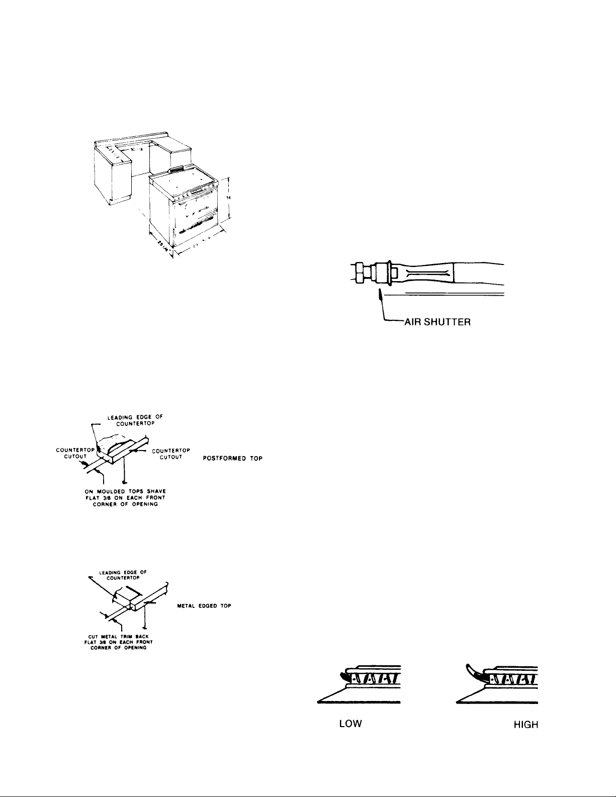
C. On post formed (moulded) tops, shave the front
corner of cabinet opening flush with countertop in
area which will be underneath front corners of range
top (3/8"). (See Figure 12.)
Figure 12
D. On countertops with front metal trim, cut metal trim
back 3/8" from front corner of opening. (See Figure
--.)
and turned fully counterclockwise, the electrode between the flash tubes will start sparking and continue
as long as the knob is held in this position. After the
burner ignites, move the knob to the "ON" position of
the valve. At this time the sparking will cease. There
are no standing pilots that have to be lighted or
adjusted.
2. Top Burner Adjustment
The air shutter (see Figure 5) should be adjusted to a
proper flame. Loosen the air shutter lock screw and
adjust the air shutter so the flame has an inner cone
of bluish-green and an outer mantle of dark blue. The
flame should be soft in character. Tighten the lock
screw when the adjustment is complete.
Figure 14
NATURAL GAS BURNER ADJUSTMENT
Models with Sealed Top Burners (Below Serial
Number F0430127550)
1. Top Burners
Whenever a top burner gas valve knob is depressed
and turned fully counterclockwise, the electrode built
into the burner cap will start sparking and continue as
long as the knob is held in this position. After the
burner lights, move the knob to the "HI" position of the
valve. At this time the sparking will cease. There are
no standing pilots that have to be lighted or adjusted.
2. Top Burner Adjustment
No gas input adjustment is necessary as the burner is
equipped with a fixed orifice. There is no shutter to
adjust.
Figure 13
ADJUSTMENTS AND LP CONVERSION
NATURAL GAS BURNER ADJUSTMENT
Models Without Sealed Top Burners
1. Top Burners
Whenever a top burner gas valve knob is depressed
RC231002 Rev. 3 12
Low burner flame may be adjusted by turning adjustment screw in center of valve stem. Normally, the low
flame should be adjusted to the minimum steady blue
flame. Check the adjustment by turning from high to
low several times to see that the burner does not go
out.
Figure 15
Top Burner Setting
OR
Page 14
INSTALLATION INSTRUCTIONS
Models with Sealed Top Burners (Above Serial
Number F0430127550)
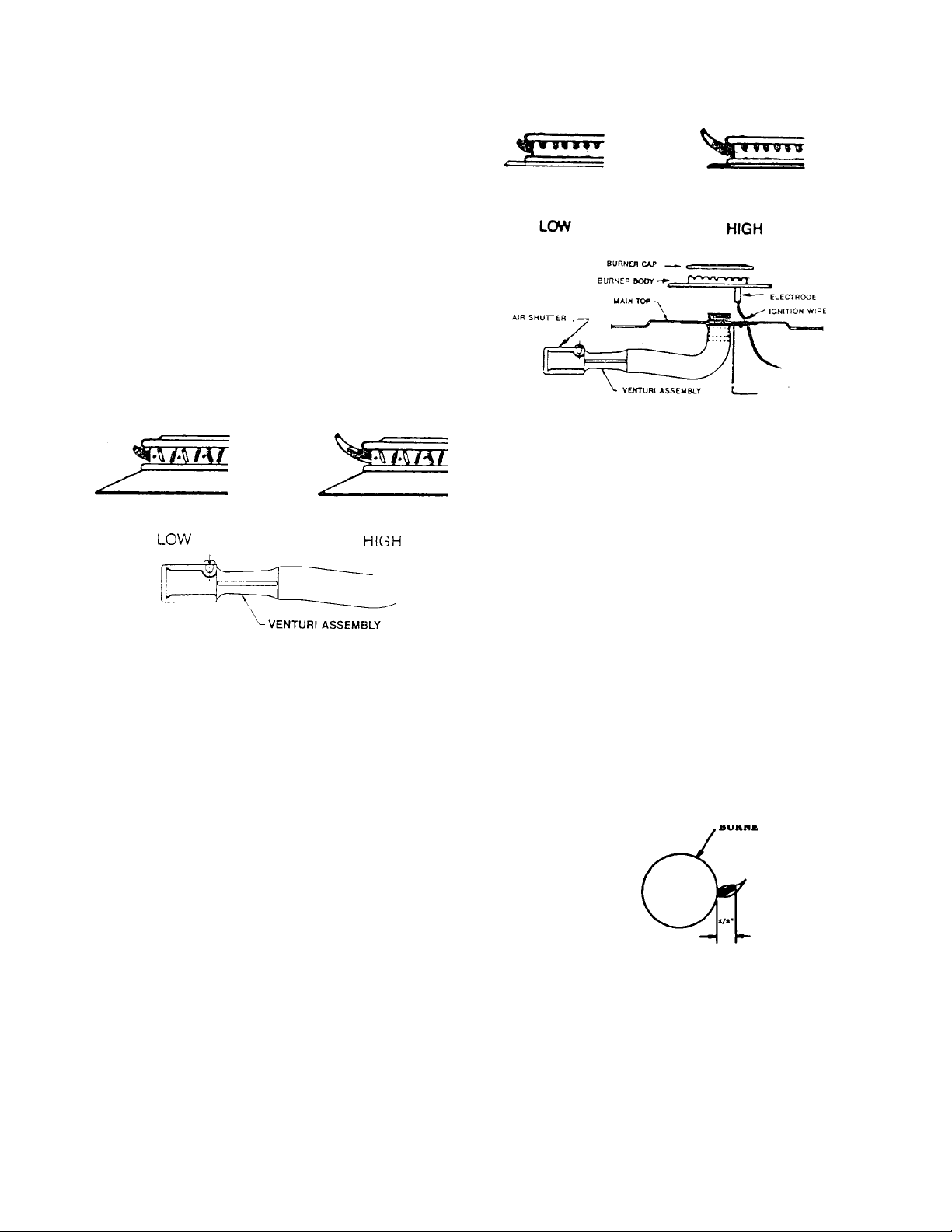
The air shutters (see Figure 6) should be adjusted for a
proper flame. Adjust the air shutter so that the flame has
an inner cone of bluish-green and an outer mantle of dark
blue. The flame should be soft in character. To adjust the
air shutter to close the opening to decrease the air or
enlarge the opening for more air. Tighten the lock screw
when the adjustment is complete.
Low burner flame may be adjusted by turning adjustment
screw in center of valve stem. Normally, the low flame
should be adjusted to the minimum steady blue flame
(approximately 1/4" flame length). Check the adjustment
by turning from high to low several times to see that the
burner does not go out.
Figure 17
LOWER OVEN BURNER - RST
The appearance of properly adjusted oven burner flame is
a bluish-green inner cone and a dark blue mantle. The
flame characteristics should be clean and soft with no
yellow tips. Blowing or lifting of the flame should not occur.
Figure 16
Models with Cast Top Burners
The air shutters (See Figure 7) should be adjusted for a
proper flame. Adjust the air shutter so the flame has an
inner cone of bluish-green and an outer mantle of dark
blue.
For Access to the Air Shutters:
Lift off four (4) burner caps. Remove one (1) screw at each
burner body. Pull each burner body upwards and disconnect the ignition wire at the electrode. Remove one (1) flat
headed screw at each burner and lift off main top. Remove
plenum box covers (when so equipped).
To Adjust the Air Shutter:
Loosen the lock screw. Move the air shutter to close the
opening to decrease the air or enlarge the opening for more
air. Tighten the lock screw when the adjustment is complete.
Low burner flame may be adjusted by turning adjustment
screw in center of valve stem. Normally, the low flame
should be adjusted to the minimum steady blue flame
(approximately 1/4" flame length). Check the adjustment
by turning from high to low several times to see that the
burner does not go out. (See Figure 8.)
1. An electric ignitor is used to light the burner. DO NOT
attempt to insert any object into the opening of the protective shield surrounding the ignitor coil. Do not attempt to
clean this area.
2. The burner flame should be 1/2" long when the air
shutter is correctly adjusted. (See Figure 8.) The air
shutter is located at the lower right of the access area,
above the gas valve. To adjust the air shutter, loosen the
lock screw. Move the air shutter to close the opening to
decrease the air or enlarge the opening for more air.
Tighten the lock screw when the adjustment is complete.
Figure 18
UPPER OVEN BURNER ADJUSTMENT - RST
The burner flames should be 3/8" long when the air shutter
is correctly adjusted. The air shutter is located at the left
side of the upper oven burner. To adjust the air shutter,
loosen the lock screw. Move the air shutter to close the
opening to decrease the air or enlarge the opening to
increase the air. Tighten the lock screw when the adjustment is complete.
13 RC231002 Rev. 3
Page 15
INSTALLATION INSTRUCTIONS
BROIL BURNER
Burner Adjustment
1. No gas input adjustment is necessary as the infrared
burner is equipped with a fixed orifice. There is no air
shutter to adjust.
2. An electric ignitor is used to light the burner. DO NOT
attempt to insert any object into the openings of the
protective shield surrounding the ignitor coil. Do not
attempt to clean this area.
3. The burner may have a hazy or fuzzy appearance
when in operation. This haze may be 3/8" thick
maximum and is normal for this type of burner.
UPPER OVEN FLAME CHARACTERISTIC
ADJUSTMENT
The appearance of a properly adjusted gas flame is one
having an inner cone of bluish-green and an outer mantle
of dark blue. The length of the inner cone flame will be
about 3/8" when correctly adjusted. (See Figure 9.) Flame
characteristics should be clean but soft.
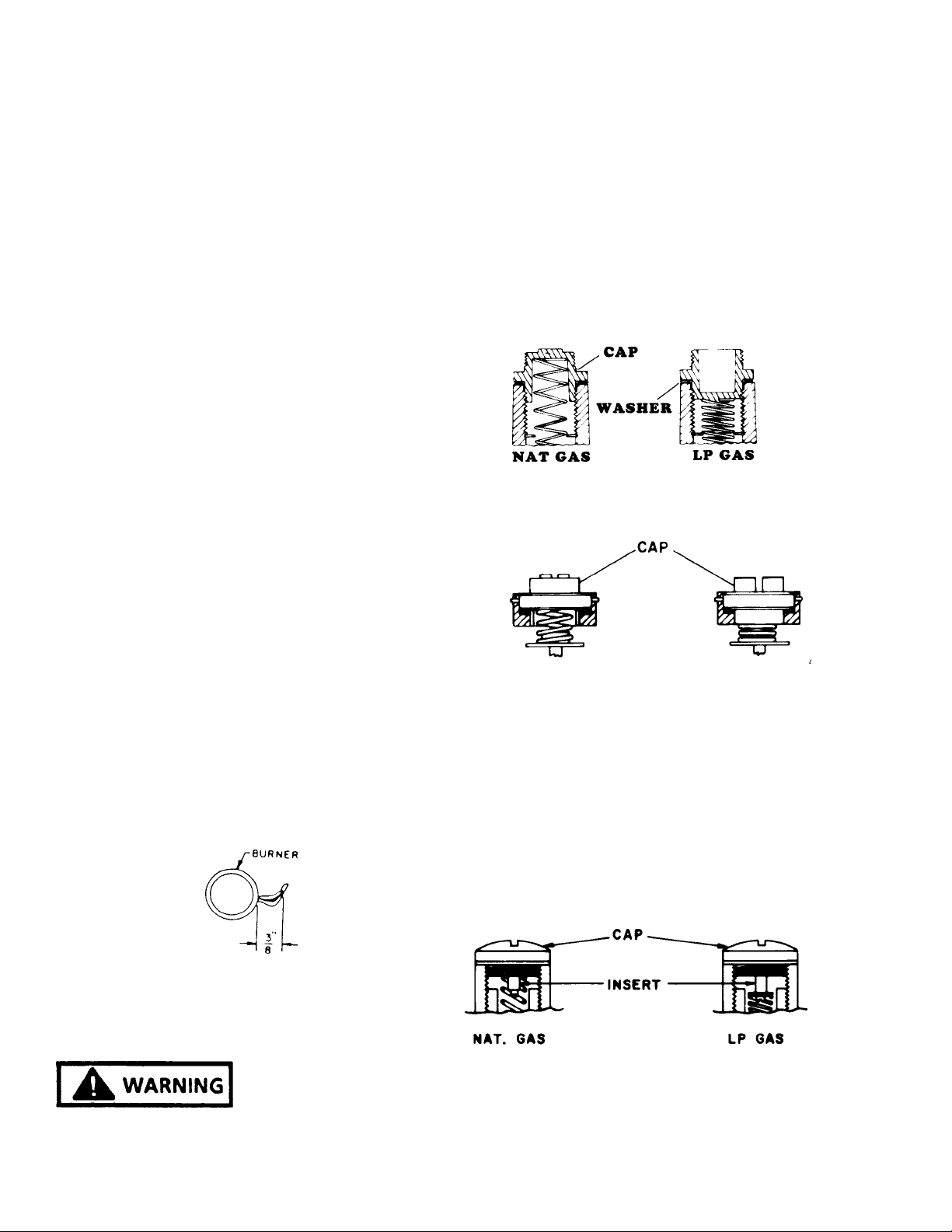
PRESSURE REGULATOR (On Range)
Remove the cap marked "Nat" and reverse it to read "LP".
Be sure not to disturb or remove the spring beneath the
cap. Also make sure the fiber washer is between the cap
and the body of the regulator. See Figure 10 for the
correction position of the cap.
Remove the cap with the screwdriver slot and replace
upside down. This plug will then have the marking "LPG10".
Be sure not to disturb or remove the spring beneath this
plug. See Figure 11 for correct position of plug.
Figure 20
OR
1. An electric ignitor is used to light the burner. DO NOT
attempt to insert any object into the openings of the
protective shield surrounding the ignitor coil. Do not
attempt to clean this area.
2. Oven Burner Adjustment
The burner flame should be 3/8" long when the air
shutter is correctly adjusted. (See Figure 9).
The air shutter is located at the left side of the upper oven
burner. To adjust the air shutter loosen the lock screw.
Move the air shutter to close the opening to decrease the
air or enlarge the opening to increase the air. Tighten the
lock screw when the adjustment is complete.
Figure 19
LP CONVERSION
Figure 21
OR
Remove the cap with the screwdriver slot. Remove the
black insert marked "Nat" from the cap. (This is a tight fit
in the cap.) Reverse this insert and carefully push it firmly
into the hole in the cap. The marking "LP" will now be
showing on the insert. Be sure the insert is pressed into the
shoulder. Also, be sure not to disturb the spring in the body
of the regulator.
Replace the cap in the body of the regulator and tighten.
See Figure 12 for the correct position of the insert.
NATURAL TO LP GAS CONVERSION
FIRE OR EXPLOSIION
HAZARD
THIS UNIVERSAL RANGE IS PREADJUSTED FOR
OPERATION ON "NATURAL" GAS AS SHIPPED FROM
THE FACTORY. TO USE THE APPLIANCE ON LP GAS,
YOU MUST DO THE FOLLOWING:
RC231002 Rev. 3 14
Figure 22
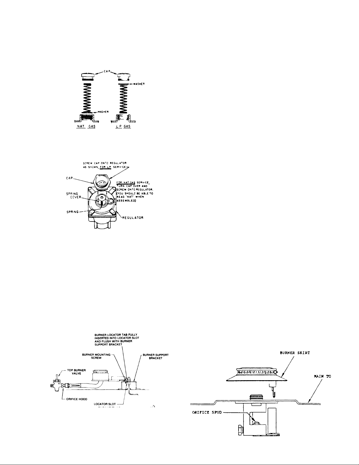
Remove the cap with screwdriver slot. Carefully remove
the spring and washer (washer will be at bottom of spring).
Reverse so that washer is at top of spring and reinstall
spring and washer.
Page 16
INSTALLATION INSTRUCTIONS
Remove the cap in the body of the regulator, over the
washer and spring, and tighten cap. See Figure 13 for the
correct position of the washer and spring.
Figure 23
OR
Figure 24
FLAME APPEARANCE
The air shutter (see Figure 17) should be adjusted for a
proper flame. Adjust the shutter so the flame has an inner
cone of bluish-green and an outer mantle of dark blue. The
flame should be soft in character.
NOTE: On LP gas a slight yellow tip will be visible on top
burner flames, but will not affect burner performance.
MODELS WITH SEALED TOP BURNERS
NOTE: Sealed Top Burner Models with Serial Number
Date Codes F006 through F009 are for use on Natural Gas
only and are not field convertible for use on LP gas.
TOP BURNER ADJUSTMENT (Below Serial Number
F0430127550)
ORIFICES
Universal Models (Natural or LP) are shipped from the
factory orificed for Natural Gas. IF THEY ARE TO BE
USED ON LP GAS, the burner orifice spuds must be
changed. They will be found wired to the inlet pipe behind
the storage drawer. The proper orifice for use on Bottled
(LP) Gas is red colored and stamped #68 (drill size). BE
SURE to use proper burner spud for the gas in use. Rewire
the Natural Gas orifice spuds to the inlet pipe for future
conversion.
MODELS WITHOUT SEALED TOP BURNERS
TOP BURNER ADJUSTMENT
ORIFICES
Remove four (4) top burners by removing the mounting
screws and lifting out of bracket. Then turn down the orifice
hoods onto the pins being careful not to drive pin into the
valve or to distort the hole through the center of the pin.
Reinstall the top burners and mounting screws. (See
Figure 15.)
FIGURE 25
Nat. Gas LP Gas
Burner Spud 54 68
(Red colored for
identification)
TO CONVERT
Remove four (4) top burners by pulling upwards. (See
Figure 26.) Remove the two (2) flat headed screws at each
burner and lift off main top. Replace the burner orifice
spuds using a 5/16" nut driver. Reinstall maintop and
burners. To replace the burners, position the ignitor over
the hole at the rear of each burner opening and push the
burner down onto the burner base until the skirt contacts
the maintop.
15 RC231002 Rev. 3
Figure 26
Page 17
INSTALLATION INSTRUCTIONS
BURNER ADJUSTMENT
No gas input adjustment is necessary as the burner are
equipped with fixed orifices. There are no shutters to
adjust. NOTE: On LP gas a slight yellow tip will be visible
on top burner flames, but will not affect burner performance.
OR
TOP BURNER ADJUSTMENT (Above Serial Number
F0430127550)
TO CONVERT
Lift off four (4) burner caps. (See Figure 27.) Remove one
(1) screw at each burner body. Pull each burner body
upwards and disconnect the ignition wire at the electrode.
Mark wires for identification on reassembly. Remove one
(1) flat headed screw at each burner and lift off main top.
Remove plenum box covers (when equipped). Remove
two (2) screws from each venturi mounting bracket and
remove venturi assemblies.
Turn the orifice hoods onto the pins. The orifices should be
turned snug onto the pins careful not to drive pin into the
valve or distort the hole through the center of the pin.
Reinstall the burner bodies and caps.
Remove one (1) flat headed screw at each burner and lift
off main top.
Remove plenum box covers. Remove two (2) screws from
each venturi mounting bracket and remove venturi assemblies.
Turn the orifice hoods onto the pins. The orifice should be
turned snug onto the pins careful not to drive pin into the
valve or distort the hole through the center of the pin.
Reinstall the burner bodies and caps.
The air shutters should be adjusted for a proper flame.
Adjust the air shutter so that the flame has an inner cone
of bluish-green and an outer mantle of dark blue. The
flame should be soft in character. To adjust the air shutter,
loosen the lock screw. Move the air shutter to close the
opening to decrease the air or enlarge the opening for more
air. Tighten the lock screw when the adjustment is complete. Reinstall the plenum box covers, main top and main
top burners in reverse order of removal. NOTE: On LP
gas a slight yellow tip will be visible on top burner
flames, but will not affect burner performance.
Figure 27
MODELS WITH CAST BURNERS
TO CONVERT
Lift off four (4) burner caps. (See Figure 28.) Remove one
(1) screw at each burner body. Pull each burner body
upwards and disconnect the ignition wire at the electrode.
RC231002 Rev. 3 16
Figure 28
OVEN BURNER (Upper and Lower Oven) (RST)
ORIFICES
Turn down the orifice hood onto the pin. The orifice should
be turned snug onto the pin being careful not to drive pin
into the valve or to distort the hole through the center of the
pin.
LOWER OVEN FLAME CHARACTERISTIC
ADJUSTMENT
The appearance of a properly adjusted oven burner flame
is a bluish-green inner cone and a dark blue mantle. The
flame characteristics should be clean and soft with no
yellow tips. Blowing or lifting of the flame should not occur.
The burner flame should be 1/2" long when the air shutter
is correctly adjusted. (See Figure 18.)
An electric ignitor is used to light the burner. DO NOT
attempt to insert any object into the openings of the
protective shield surrounding the ignitor coil. Do not
attempt to clean this area.
Page 18
INSTALLATION INSTRUCTIONS
found under the plate in the center of the burner box. BE
SURE to use the proper burner spud for the gas in use.
Reinsert Nat. Gas orifice in burner box with louvers facing
to rear of unit.
Nat. Gas LP Gas
Burner Spud 50 58
(Silver colored for identi-
Figure 29
fication)
The air shutter is located in the lower access area. To
adjust the air shutter, loosen the lock screw. Move the air
shutter to close the opening to decrease the air or enlarge
the opening for more air. Tighten the lock screw when the
adjustment is complete.
OVEN BURNER (RSS)
1. Orifices
Turn down the orifice hood onto the pin. The orifice
should be turned snug onto the pin being careful not
to drive pin into the valve or to distort the hole through
the center of the pin.
2. Low Oven Flame Characteristic Adjustment
a. The appearance of a properly adjusted oven burner
flame is a bluish-green inner cone and a dark blue
mantle. The flame characteristics should be clean
and soft with no yellow tips. Blowing or lifting of the
flame should not occur. The burner flame should be
1/2" long when the air shutter is correctly adjusted.
b. An electric ignitor is used to light the burner. DO
NOT attempt to insert any object into the openings of
the protective shield surrounding the ignitor. Do not
attempt to clean this area.
MODELS WITH SEALED TOP BURNERS
Universal models (Nat. or LP) are shipped from the factory
orificed for Nat. Gas. IF THEY ARE TO BE USED ON LP
GAS, the burner orifice spud must be changed. This will be
found wired to the inlet pipe behind the storage drawer.
The proper orifice for use on Bottled (LP) gas is silver
colored (Nickel plated) and stamped #58 (drill size). BE
SURE to use the proper burner spud for the gas in use.
Rewire the Natural Gas orifice spuds to the inlet pipe for
future conversion.
TO CONVERT
Remove oven door and storage drawer. Shut off valve on
gas line that runs from the pressure regulator to the gas
valve.
Remove the two (2) screws fastening the broiler burner to
the oven tank at front of burner. Remove the burner by
pulling front end down to expose the burner orifice spud in
the rear wall. Be careful not to break the ignitor. Lay the
burner aside carefully with the screen side up. Replace the
burner orifice spud using a 5/16" nut driver. Reverse the
procedure to reinstall the burner.
BURNER ADJUSTMENT
c. The air shutter is located in the lower accessed
area. To adjust the air shutter, loosen the lock screw.
Move the air shutter to close the opening to decrease
the air shutter to close the opening to decrease the air
or enlarge the opening for more air. Tighten the lock
screw when the adjustment is complete.
ULTRA-RAY® BROILER BURNER
An electric ignitor is used to light the burner. DO NOT
attempt to insert any object into the openings of the
protective shield surrounding the ignitor element. Do not
attempt to clean this area.
MODELS WITHOUT SEALED TOP BURNERS
Universal models (Nat or LP) are shipped from the factory
orifices for Nat gas. IF THEY ARE TO BE USED ON LP
GAS, the burner orifice spud must be changed. This will be
17 RC231002 Rev. 3
No gas input adjustment is necessary as the infrared
burner is equipped with a fixed orifice. There is no shutter
to adjust.
The burner may have a hazy or fuzzy appearance when in
operation. This haze may be 3/8" thick, maximum and is
normal for this type of burner.
RANGE FEATURE CHECKOUT
Check all range features, including lights, clocks, etc. for
proper operation.
Page 19

INSTALLATION INSTRUCTIONS
CHECKOUT PROCEDURE OF CLEAN CYCLE
OPERATION - RSS (WITH MECHANICAL TIMER;
FOR OTHER MODELS FOLLOW TIMER
INSTRUCTIONS)
REMOVE OVEN RACKS, BROILER PAN AND GRID.
MAINTENANCE INSTRUCTIONS
1. Keep appliance clear and free from combustible
materials, gasoline, cleaning fluids, and other flammable vapors and liquids.
A. Set the range clock to the correct time of day. (If not
set properly).
B. Push the turn the start dial on the backguard to the
approximate time of day until set stem pops out.
C. To establish length of clean time, turn the stop dial 1
1/2 hours to 2 hours ahead of start time. On electronic
clock models push clean button on timer for 3-hour
clean time.
D. Close and latch oven door, moving the latch arm to
the far right. (clean position).
E. Turn the oven heat control, on control panel, clock-
wise to "CLEAN" position. Then, turn selector switch
to the "CLEAN" setting.
F. A 15-20 second delay should occur, and the oven
indicator light should then come on.
G. After the cycle begins, the oven should reach a
temperature in excess of normal broiling (approximately 700°). The "CLEAN" indicator light should
come on, and the terminal lock system should lock
and secure the oven door.
H. Turn selector switch from "CLEAN" to "OFF" and heat
control to "OFF".
I. When oven temperature has lowered to approxi-
mately 700° or less, the lock system should unlock the
oven door allowing the latch handle to move freely.
2. Gas burners need sufficient air to operate. Objects
should not be placed in front of or on maintop rear of
range while in use. This could obstruct the air flow
needed for combustion and vent for flue products.
BURNER CLEANING -
The burner heads are made of aluminum and should not be
subjected to scouring or abrasive pads. Never not be
subjected to scouring or abrasive pads. Never use steel
wool or oven cleaners on the burner heads or they will dull
and not regain their original luster.
To clean the burners, remove the burner grates and push
the main top towards the rear of the range until the front
tabs are free. Then raise the main top and remove or
engage the main top support. This will support the main top
while the burners are removed for cleaning.
Before attempting to remove the burners, be certain the
four (4) burner mounting screws which retain the burners to
the burner supports are removed. If the screws are still
secured, they can be removed with a Phillips screwdriver.
To remove the burners, release the burner head brackets
from the burner support, lift up and pull towards the rear of
the range.
To replace the burners slip the Venturi (long, thin end) over
the burner orifice and then position the burner locating
brackets into the burner support channel. Reinstall the
burner mounting screws.
DEFECTS
Any defects or faulty or damaged parts must be reported
immediately and steps taken to correct them through
normal dealer service channels.
POWER FAILURE
In the event of a power failure, safe manual lighting of the
top burners is possible. To do this, hold a lighted match at
the desired burner head (the part projecting above the
main top), turn the top burner control knob to the light
position.
The flame height can now be adjusted to the desired size.
The broil and oven burners cannot be operated during a
power failure and no attempt should be made to do so.
RC231002 Rev. 3 18
Wiping the burners following each use will remove spillover
deposits and grease spatters before these soils get a
chance to harden on the surface. Burnt soil can be cleaned
by soaking the burners in warm water and a dishwashing
liquid detergent such as "Dove" or "Lux". A dishcloth or
nonabrasive pad (such as Dobie pad) should be used to rub
the burner caps after the soaking period. Be sure the
burners are dry, as water lodged in the burner parts might
cause an uneven flame or interfere with automatic lighting.
If stains still remain after soaking, you can soak any heavily
soiled burners in a solution of two tablespoons of "Dip-it"
per quart of water. Use a large pan and enough water so
the cap and base part of the burner assembly can be
completely immersed; bring water to a boil, remove vessel
from burner, and add measured amount of "Dip-it". Immerse the burner in the hot solution and soak for 20
Page 20
INSTALLATION INSTRUCTIONS
minutes, no longer. Be sure the liquid completely covers
the cap and base portion of the assembly. After 20
minutes, remove burner, cool slightly and rinse thoroughly
with cold water. Be sure hands are protected to prevent
burns from hot water. Be sure all the solution is completely
rinsed off both the inside and outside of the burner. If some
stains still remain, rub with a "Dobie" pad.
The burner may then be left to dry at room temperature or
be placed in the oven at 170° for 1/2 hour. BE SURE TO
PROTECT YOUR HANDS WHEN REMOVING DRIED
BURNERS FORM THE OVEN.
Figure 31
NOTE: These thermostats (Robertshaw) have a cement
coating over the adjusting screw. Evidence of attempts to
adjust these thermostat nullifies the warranty.
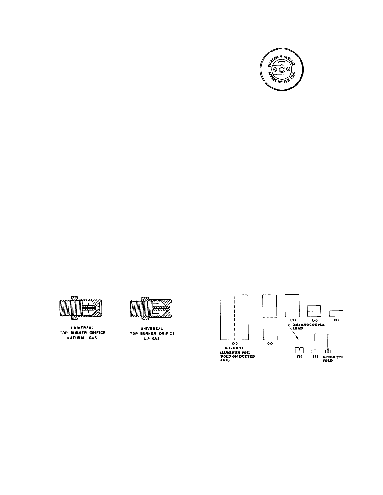
UNIVERSAL GAS ORIFICES
With the exception of the Broiler Burner and Sealed Top
Burner, orifices for these models are of the coaxial type.
They contain a double coaxial orifice hood and universal
pin. The hood orifice is sized for Natural Gas (6 inches
water column pressure). The pin orifice is sized for LP Gas
(11 inches water column pressure).
The orifice is adjusted for Natural gas as shipped from the
factory. It must be adjusted for use on LP gas. This
requires that the orifice hood be screwed or turned down
approximately two (2) turns onto the pin. The hood should
be turned down snug but not tight to the point where it
damages or distorts the pin. (See Figure 19.)
When set up for Natural Gas, gas flows around the pin and
through the orifice of the hood which is sized for Natural
Gas. When the hood is screwed down for LP gas, the gas
flow is only through the hollow pin which is sized for LP gas.
For Thermostat Calibration on models with the Electronic Range Control (ERC), see section on ERC
Operating and Testing Procedures.
When making any temperature adjustments, a reliable test
instrument should be used to accurately determine the
oven temperature.
A reliable test instrument of the thermocouple type is
preferred which will allow temperature readings with the
door closed.
Position the thermocouple clip of the test instrument on the
center of the oven rack that is positioned in the center of the
oven cavity. The thermocouple of the test instrument
should be "weighted" or "loaded" in order to represent more
closely the average cooking temperature of the oven
versus the on-off cycling of the thermostat with the full rate
gas valve. The procedure for loading a thermocouple is
illustrated in Figure 20.
Figure 30 - Universal Orifice
OVEN THERMOSTAT KNOB ADJUSTMENT
Models without electronic Range Control (ERC)
Cooking recipes are written to take into consideration that
oven thermostats have manufacturing tolerances, and
may not provide an average temperature exactly on the
thermostat setting. If the temperature average reading is
beyond the ±25° tolerance range, a limited adjustment can
be made with the adjustable skirt on the knob. The
adjusting screw on the thermostat is sealed and no adjustment can or should be attempted. The rear of the adjustable skirt shown here is self-explanatory.
19 RC231002 Rev. 3
Figure 32 - "Loading" A Thermocouple
An 8 1/2 x 11-inch piece of aluminum foil should be folded
five (5) times, doubling the thickness with each fold. After
the fifth fold, place the thermocouple in the center of the
aluminum piece as shown and fold once more. Finally, fold
the sides so the foil clings to the thermocouple. The loaded
thermocouple will then provide temperature readings on
the thermometer that more closely resemble the mean or
average temperature of the oven as it cycles on and off
above and below the temperature setting.
With all the controls properly set for "Bake", turn the oven
thermostat to 350°.
Page 21
INSTALLATION INSTRUCTIONS
After the oven has cycled for 25 to 30 minutes, note the
temperature that the oven cycles ON and OFF. For
example, at 350° setting the oven cycles between 335° and
355°. This provides a mean or average temperature of
345°F., well within the ±25°F specification.
GAS PRESSURE
Correct ignition and operation of the burners are dependent
upon adequate gas pressure. The regulator is designed to
provide pressure of approximately six (6) inches water
column pressure (WCP) for natural gas and approximately
eleven (11) inches for WCP for liquid propane (LP) gas,
provided the universal type gas regulator and gas valves
have been correctly set up for the type gas employed.
These pressures therefore require that the minimum supply
pressure to the regulator must be at least six (6) inches
WCP for natural gas and eleven (11) inches WCP for LP
gas, with maximum pressure not to exceed fourteen (14)
inches WCP.
MEASURING GAS PRESSURE
Equipment for measurement of gas pressure varies from
pressure meters and gauges to the relatively simply and
most commonly used manometer. If it is used, follow the
directions supplied with the unit. The following informations
covers the use of a manometer.
zero level.
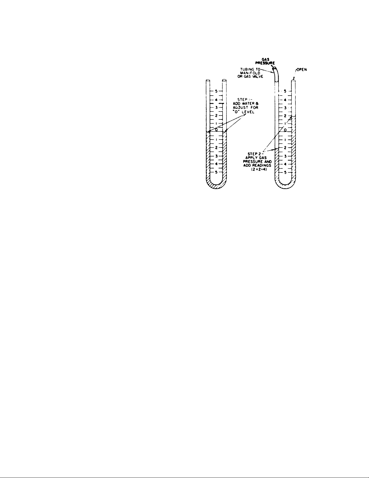
Figure 33 - The Mannometer
A manometer is simply a U-shaped tube of clear plastic or
glass (see illustration). A scale in inches is located between
the two (2) legs of the "U". In use, the tube is filled with
sufficient water to achieve a level at "0" inches. One end
of the tube is connected to the range manifold or gas valve
orifice while the other end of the tube or leg is open. When
gas pressure is applied, the water on the gas side of the tube
is pushed down and the water in the other leg rises up
against the atmospheric pressure on the open end. The
sum of the readings below the zero level and above the
level will provide the gas pressure in inches water column,
or the water column height which the gas pressure will
support against the atmospheric pressure on top of the
water column. The manometer therefore indicates gas
pressure in inches water column. This conforms with the
gas specifications for gas appliances which are given as
inches WCP or inches water column pressure.
USING THE MANOMETER
The usual procedure for taking the pressure reading is to
connect the tubing to one of the gas valve orifice hoods and
turn on the valve. A full load reading should be taken by
turning on all of the top burners and the oven burner to
assure that the pressure under a full load is adequate.
Figure 33 shows four (4) inches water column pressure
(WCP), two (2) inches above and two (2) inches below the
RC231002 Rev. 3 20
Page 22
SAFE OPERATING PROCEDURES
SAFETY PRECAUTIONS READ BEFORE OPERATING
THE RANGE.
are easily hit. UTENSIL HANDLES SHOULD BE
TURNED INWARD AND NOT EXTEND OVER ADJACENT SURFACE BURNERS to minimize burns,
ignition of flammable materials, and spillage due to
unintentional contact with the utensil.
Accidents are always tragic, especially because so many
of them could have been prevented with a little care and
judgement. Here are some basic good practices to follow
for safe use of the gas range.
1. Be sure the range is installed by a qualified technician
and is properly grounded.
2. Never use the range for warming or heating the room.
This warning is based on safety considerations.
3. Wear proper apparel - loose fitting or hanging
garments should never be worn when operating the
range.
4. Do not repair or replace any part unless specifically
recommended in the manual. All other servicing
should be referred to a qualified service technician.
5. Flammable materials should not be stored near the
range.
6. Do not use water on grease fires. Smother fire or
flame or use dry chemical (such as baking soda) or
foam type extinguisher.
7. Use only dry potholders. Moist or damp potholders on
hot surfaces may result in burns from steam. Do not
use a towel or other bulky cloth.
8. Children should not be left alone or unattended in
area when the range is in use. They should never be
allowed to sit or stand on any part of the range.
9. Select utensils large enough to properly contain food
and avoid boil-overs or spillovers. This will both save
cleaning and prevent hazardous accumulations of
food, since heavy splattering or spillovers left on a
range can ignite. Pan size is especially important in
deep-fat frying.
12. Never leave range burners at high heat settings. Boilover causes smoking and greasy spillovers that may
ignite.
13. Clean range with caution. If a wet sponge or cloth is
used to wipe spills on a hot cooking area, be careful
to avoid steam burns. Some cleansers can produce
noxious fumes if applied to hot surfaces.
14. Do not touch surface area near burner units and
burner caps. During and after use, these areas may
be hot enough to cause burns. Avoid contact with
these areas by clothing or other flammable materials
until they have had sufficient time to cool.
15. Do not heat unopened food containers - build-up of
pressure may cause container to burst and result in
injury.
16. Do not store items of interest to children in
cabinets above the range. Children climbing on
the range to reach items could be seriously injured.
17. GREASE - Grease is flammable and should be
handled carefully. Never leave any cooking operation unattended. Let fat cool before attempting to
handle it. Wipe spillovers immediately.
18. Burner flame should be adjusted so that they do not
extend beyond the edge of the utensil. This warning
is based on safety considerations.
19. Never sit, step, or stand on any part of the range or
injury may result.
10. TYPE OF UTENSILS - Avoid pans that are unstable
and easily tipped. In choosing pans, look for easily
grasped handles that will stay cool. Pans that are too
heavy when filled with food can also be a hazard. If
pan handles twist and cannot be tightened, discard
the pan.
11. HANDLES - Always turn pan handles to the side or
back of the range - not out into the room where they
21 RC231002 Rev. 3
Page 23
SAFE OPERATING PROCEDURES
OPERATING INSTRUCTIONS
SAFETY TIPS
Some "common sense" rules to remember:
· Always be certain that the oven parts are cool before
touching them when hands are not protected by a
potholder.
· Always use a dry potholder, never a moist one, nor a
trailing cloth, to avoid possible burns from steam.
· Pulling out oven racks is a convenience when lifting
heavy foods, but caution should be used against
possible burns from touching hot surface.
· For your safety, never use the range as a space
heater.
· Do not heat unopened containers such as jars, cans,
etc., in the oven. The build-up of pressure may cause
the container to burst and can cause serious personal
harm or damage the range.
· Do not use aluminum foil on the racks or oven bottom.
This will hinder heat circulation.
· Do not use aluminum foil on the racks or oven bottom
when cleaning. The self-cleaning feature makes this
unnecessary.
· Do not attempt to clean the oven or broiler burner
ignitor assembly. The ignitors are electrically operated and the danger of electric shock is present.
· Do not place baking utensils directly on the oven
bottom.
· Do not use disposable or substitute broiler pans. The
broiler pan and grid provided with the range have
been scientifically designed to keep drippings cool so
they will not become hot enough to ignite.
· Always remove the broiler pan and grid from the oven
when baking and roasting. A possible fire hazard
could exist if a soiled pan and grid are left in the oven.
Also, any drippings on the grid will become baked on
and will be very difficult to remove.
· Never cover the broiler grid with aluminum foil. It may
trap grease and cause it to smoke. If desired, place
a sheet of aluminum foil to line the broiler pan
underneath the broiler grid to ease clean up. (A cup
of water placed in the broiler pan will also minimize
clean up.)
· Never use the range as storage space.
· Never store flammable items in the storage drawer.
all broiling is done with a fast, searing heat, no temperature
selection is used except with certain recipes). The burner
lights automatically in 50 - 60 seconds. During the broil
cycle the burner will cycle on and off. For programming
information on models with the Electronic Range Control,
see Section III, Operation and Troubleshooting, ERC
Control.
Things to Remember:
CLOSE THE DOOR COMPLETELY FOR ALL BROILING.
Ultra-Ray® consumes most smoke and spatter. Kitchen
stays cleaner, cooler.
DO NOT PRE-HEAT THE BROILER BEFORE USING.
BAKING
For best results preheat the oven first. Turn the selector
dial to "Manual" and the thermostat dial to the desired
temperature. The oven will light automatically. Allow the
oven to heat to temperature, approximately fifteen (15)
minutes. For programming information on models with the
Electronic Range Control, see Section III, Operation and
Troubleshooting, ERC Control.
The range is equipped with tilt proof oven racks with
automatic stops. The oven racks are removable and can
be inserted at various levels. They can be pulled to the
"STOP" position without danger of tipping. To remove the
racks, pull to the stop position, raise the forward edge, and
lift. Reverse the procedure to install racks. One or both
oven racks can be used during baking.
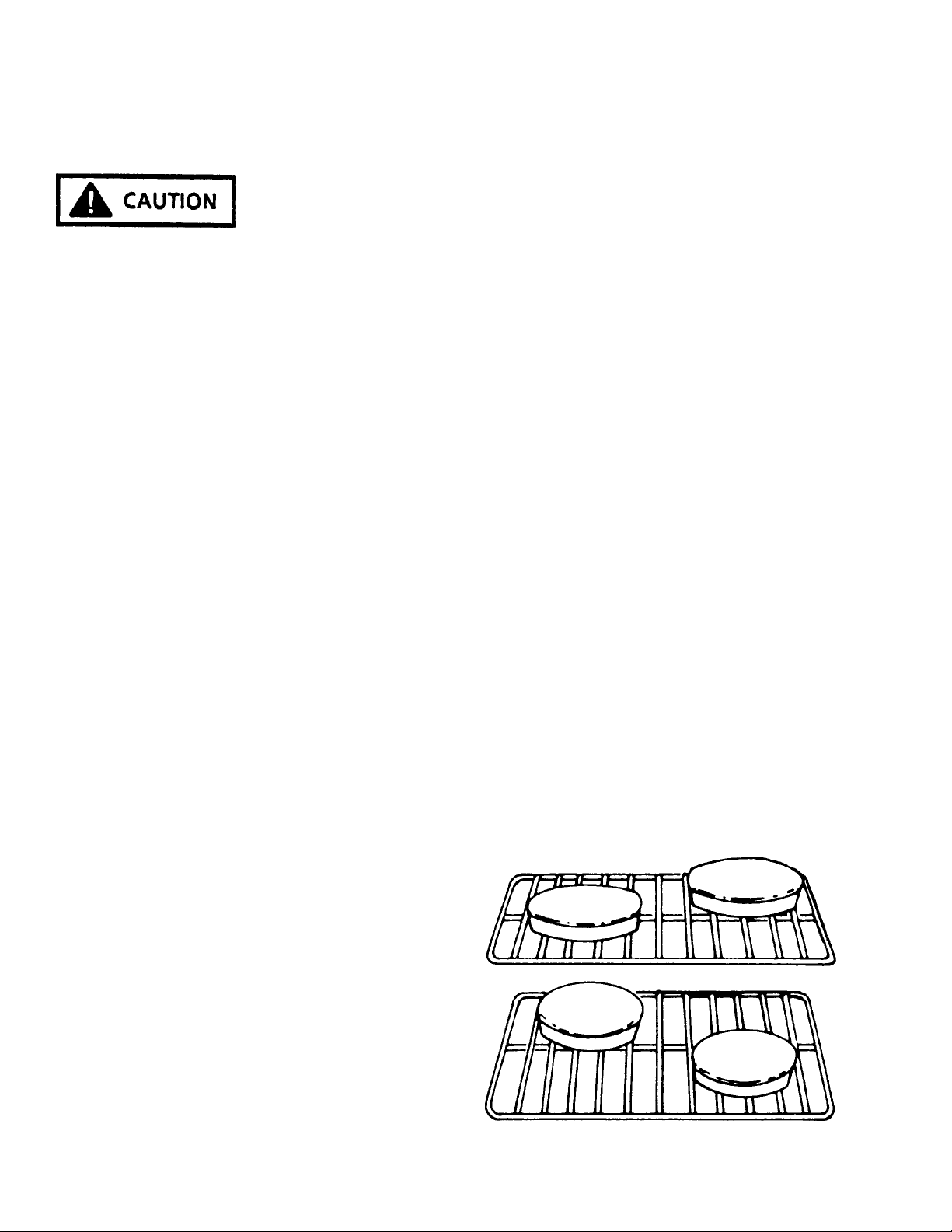
Always keep in mind that heated air in the oven must be
allowed to circulate freely. Leave at least 1 1/2" between
utensils and between utensils and the oven walls. For
example, never place one cake layer directly over another
- stagger them within the oven.
BROILING
The Ultra-Ray® Broiler
To use the Ultra-Ray® broiler, set the selector dial to
"Manual" and the temperature control dial to "Broil" (since
RC231002 Rev. 3 22
FIGURE 34
Page 24

SAFE OPERATING PROCEDURES
OPERATING THE TOP BURNERS
MODELS WITHOUT SEALED BURNERS
The top burners of some models are equipped with Tri-Set
top burner valves. These valves provide flame adjustment
for any size flame which is desired as well as "click"
positions for "LO", "MED", and "HI" settings. Depress the
knob and turn the knob counterclockwise as far as it will go.
When the burner lights, turn the knob back to the desired
flame height.
The "HI" position provides a flame which will bring water to
a full boil quickly. This is the "full on" position of the valve.
If the burner flame is turned down, an audible "click" can be
heard as the valve reaches the "MEDIUM" position. This
flame is sufficient to keep water boiling in a covered pan.
When the flame is turned down lower, a second "click" can
be heard. This is a very low or "Keep Warm" flame setting
which is the "LO" position on the valve. The low flame
provides a warming heat to keep food which is already
cooked ready to serve.
The low burner flame may be adjusted by turning adjustment screw in center of valve stem. Normally, the low
flame should be adjusted to the minimum steady blue
flame. Check the adjustment by turning from high to low
several times to see that the burner does not go out.
NOTE: When adjusting the low burner flame, the valve
stem should be held in the "LOW" position.
The Tri-Set valves are equipped with metered, fixed
orifices, and the low setting cannot be adjusted. As there
are air shutters, the burner flames can be adjusted in
accordance with the Adjustment and Calibration Instructions.
The HI-LOW valves on other models are similar but
without the "click" stops.
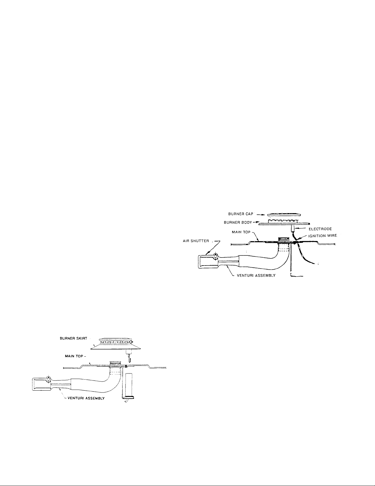
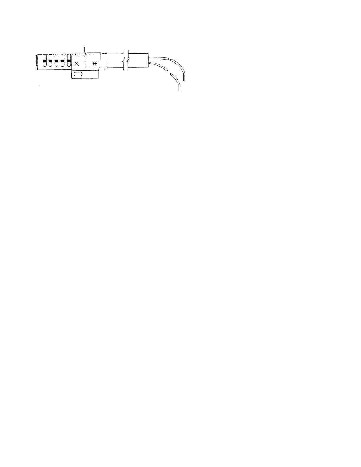
TOP BURNERS
The top burners consists of a burner and integral cap, a
flash tube and support, a gas delivery tube including
venturi and an adjustment air shutter. These burners are
designed for trouble free operation with a minimum of
parts.
MODELS WITH SEALED BURNERS
The top burners of these models are equipped with Tri-Set
top burner valves. These valves provide flame adjustment
for any size flame which is desired as well as "click"
positions for "LO", "MED", and "HI" settings.
Whenever a top burner gas valve knob is depressed and
turned fully counterclockwise, the electrode built into the
burner cap will start sparking and continue as long as the
knob is held in this position. After the burner lights, move
the knob to the "HI" position of the valve. At this time the
sparking will cease. There are no standing pilots that have
to be lighted or adjusted.
23 RC231002 Rev. 3
Page 25
OPERATION AND SERVICE PROCEDURES
(SLIDE IN MODELS)
ELECTRONIC CLOCK/TIMER
The Clock/Timer offers a time-of-day clock with a PM
designation, a Minute Timer with up to nine (9) hours and
fifty-nine (59) minutes, and cook and stop functions. The
clock and timer are set up with up and down variable speed
"slew" entry.
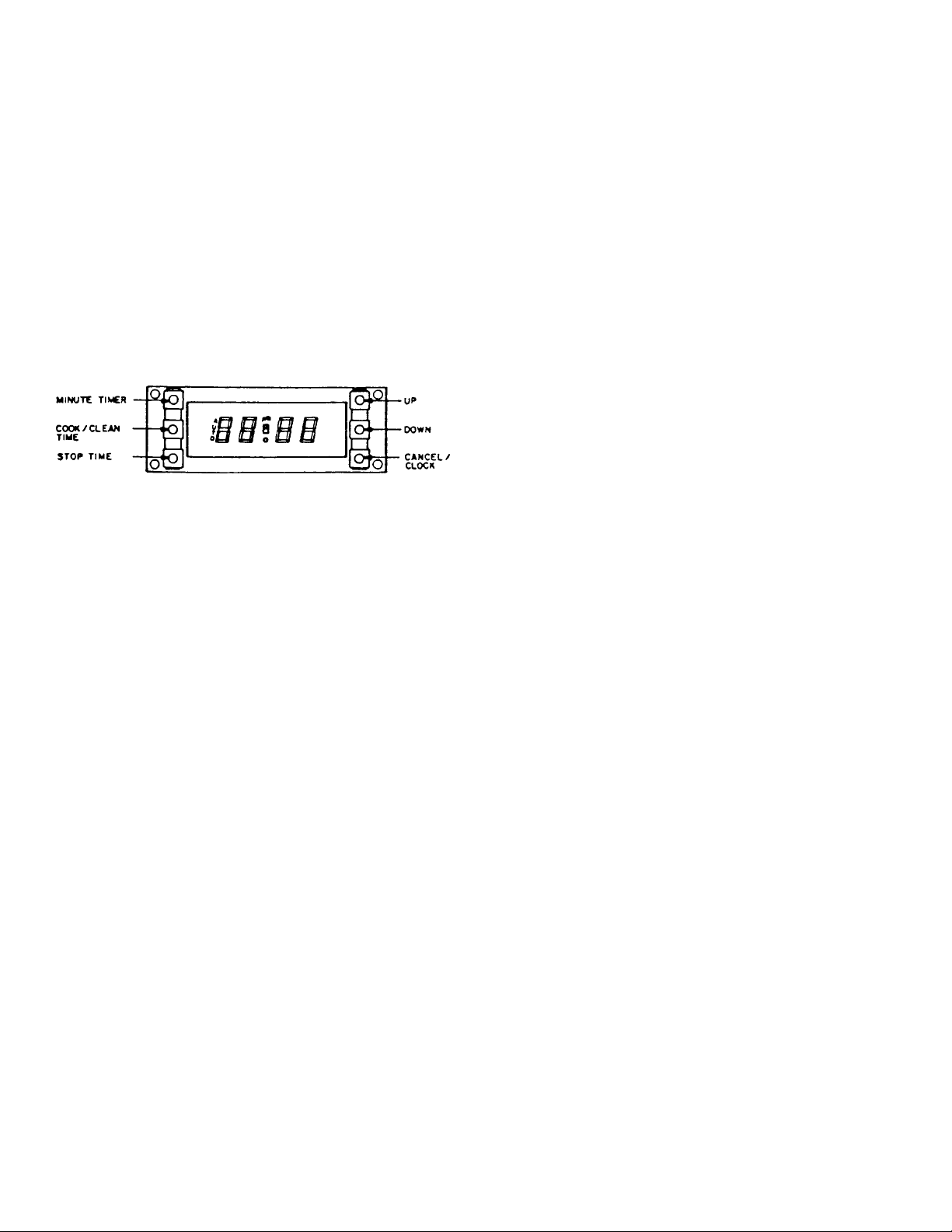
The display board consists of a vacuum fluorescent display
(VFD) with pushbutton entry. There are six (6) pushbuttons:
"MINUTE TIMER", "COOK/CLEAN TIME", "STOP TIME",
"UP" and "DOWN" and "CANCEL/CLOCK". The "UP" and
"DOWN" pushbuttons are for time setting.
Figure 56 - Electronic Clock/Timer
The Clock/Timer is a digital clock with a minute timer and
automatic control cooking cycle. The clock is set via the
function setting and slew controls. When power is connected to the unit, or a power failure of longer than three (3)
seconds occur, the display will show "12:00" flashing at the
rate of 1/2 second ON and 1/2 second OFF.
Setting the Time-of-Day
To Set the Minute Timer:
1. Display the "MINUTE TIMER" button. The timer will
display "0:00".
2. Press the "UP" button until the desired time period is
displayed, and release the "UP" button.
The minute timer is now programmed. After approximately five (5) seconds the timer display will revert
back to the Time-of-Day while continuing to count
down the programmed time. An alarm will sound
when the timer reaches "0:00". Press the "MINUTE
TIMER" button to silence the alarm. To check the
remaining time in the program, simply press the
"MINUTE TIMER" button.
The Minute Timer can also be used when the Clock/
Timer is programmed for a Timed Bake or Self-Clean
operation. NOTE: The Minute Timer does not control
oven operation.
SETTING TIMER FOR TIMED BAKE (Bake Cycle
Only)
SEMI-AUTOMATIC OPERATION
Oven starts at once and shuts off at the end of the cooking
cycles.
The clock setting is achieved by depressing the "CANCEL/
CLOCK" pushbutton first. Then key in the desired time of
day by using the "UP" and "DOWN" pushbutton keys. The
clock has a PM designation on the VFD for the PM time
setting.
The Clock/Timer also incorporates military timing capabilities. In order to change from the standard AM/PM clock
operation to military time clock operation or vice versa,
simultaneously press "COOK/CLEAN TIME" button and
the "STOP TIME" button. NOTE: The "UP" and "DOWN"
buttons must be pressed within five (5) seconds after
selecting or pressing any timing function button ("CANCEL/CLOCK", "MINUTE TIMER", "COOK/CLEAN TIME",
"STOP TIME"). If the "UP" and "DOWN" buttons are not
pressed within the five (5) second period, incorrect or no
programming will occur.
Setting the Minute Timer
The minute timer can be used for precisely time baking or
broiling operations in the oven. It can be used for timing
from one (1) minute up to nine (9) hours and fifty-nine (59)
minutes.
1. Turn selector switch knob to "AUTO".
2. Turn oven control knob to the desired baking temperature.
3. Press the "STOP TIME" button. The display will show
"0:00".
4. Press the "UP" button to set the desired stop time, and
then release the "UP" button. After approximately
five (5) seconds, the display reverts back to the Timeof-Day, "AUTO" appears on the left of the display
along with the oven indicator in the center of the
display signifying that the timed bake cooking cycle
has started. When the desired stop time is reached,
the oven indicator light goes out and an alarm will
sound for approximately ten (10) seconds. The oven
will automatically shut off. "AUTO" will continue to
blink ON and OFF indicating that the clock timer was
set for an automatic timed function and is completed.
5. Turn the selector switch to "MANUAL", oven control
to the OFF position and press the "CANCEL/CLOCK"
button.
RC231002 Rev. 3 24
Page 26

OPERATION AND SERVICE PROCEDURES
(SLIDE IN MODELS)
DELAYED TIME BAKE
Oven starts at a later time and shuts off at the end of the
cooking cycle.
1. Turn selector switch knob to "AUTO".
2. Turn oven control knob to the desired baking temperature.
3. Press "COOK/CLEAN TIME" button. The display will
show "0:00".
4. Press the "UP" button to set the desired length of
baking time. EXAMPLE: To time bake for three (3)
hours press and hold the "UP" button until "3:00"
appears on the display, then release the UP button.
5. Press the "STOP TIME" button.
6. Press the "UP" button to set the desired stop time. To
have the time bake cycle finish at five o-clock (5:00),
press and hold the "UP" button until "5:00" appears on
the display, then release the "UP" button. After
approximately five (5) seconds, the display reverts
back to the Time-of-Day and "AUTO" appears on the
left of the display indicating that the Clock/Timer is
programmed for an automatic timed function. The
clock will automatically calculate the start time. When
the starting time is reached, the oven indicator in the
center of the display will come on indicating that the
timed bake cycle has started.
When the stop time is reached, the oven indicator
turns off and an alarm will sound for approximately
ten (10) seconds. The oven will automatically turn off
and AUTO will continue to blink ON and OFF indicating that the Clock/Timer was set for an automatic
timed mode and it is completed.
7. Turn the selector switch to "MANUAL", the oven
control to the OFF position, and press the "CANCEL/
CLOCK" button.
SETTING THE TIME FOR SELF-CLEAN
4. Press the "COOK/CLEAN TIME" button. The display
will show "0:00".
5. Press the "UP" button to set the desired length of the
clean time. EXAMPLE: To self-clean the oven for
three (3) hours, press and hold the UP button until
"3:00" appears on the display, then release the "UP"
button.
After approximately five (5) seconds, the display
reverts back to the Time-of-Day and "AUTO" appears
on the left of the display along with the oven indicator
in the center of the display signifying that the clean
cycle has started.
The oven indicator light on the control panel will come
on and cycle ON and OFF with the thermostat.
6. At the end of the clean cycle the oven indicator light
and oven indicator (clock) will turn OFF, and an alarm
will sound for approximately ten (10) seconds. The
oven will automatically turn off and "AUTO" will
continue to blink ON and OFF indicating that the
Clock/Timer was set for an automatic timed mode
and it is now completed.
7. Turn the selector switch to "MANUAL", the oven
control to "OFF" and press the "CLOCK/CANCEL"
button.
8. The oven door can be opened approximately 30
minutes after the completion of the clean cycle. Do
not attempt to open the oven door latch until approximately thirty (30) minutes have elapsed, otherwise
the door lock mechanism may be damaged.
If the door will not open, wait five (5) minutes and try
again.
TO START SELF-CLEAN LATER:
1. Turn the selector switch knob to the "AUTO" position.
2. Turn the oven control counterclockwise until it stops
("CLEAN" - turn to "STOP" position).
TO START SELF-CLEAN NOW:
1. Turn the Selector switch knob to the "AUTO" position.
2. Turn the oven control counterclockwise until it stops
("CLEAN - TURN TO STOP" position).
3. Move the latch lever to the right hand (self-clean)
position. The clean indicator will now come on.
25 RC231002 Rev. 3
3. Move the latch lever to the right hand ("SELF-CLEAN")
position. The clean indicator will now come on.
4. Press the "COOK/CLEAN" button.
5. Press the "UP" button to set the length of time desired
to self-clean the oven. For example, to self-clean up
to three (3) hours, press and hold the "UP" button until
"3:00" appears on the display, then release the "UP"
button.
Page 27
OPERATION AND SERVICE PROCEDURES
(SLIDE IN MODELS)
TO AVOID THE RISK OF ELECTRIC SHOCK, PERSONAL INJURY OR DEATH DISCONNECT POWER
BEFORE SERVICING, UNLESS TESTING REQUIRES IT.
6. Press the "STOP TIME" button.
7. Press the "UP" button to set the desired stop time of
the self-clean cycle. For example, to have the selfclean end at 4 o'clock, press and hold the "UP" button
until "4:00" appears on the display, then release the
"UP" button. After approximately five (5) seconds,
the display will revert back to the Time-of-Day and
"AUTO" will appear on the left of the display indicating
the "CLOCK/TIMER" is programmed for an automatic timed operation. The clock will automatically
calculate the start time of the self-clean cycle. In
other words, a three (3) hour self-clean cycle would
begin at one (1) o'clock and end at four (4) o'clock.
When the start time of the self-clean cycle is reached,
the oven indicator in the center of the display will
come on and the clean cycle will begin.
The oven indicator light on the control panel will come
on and cycle ON and OFF with the thermostat. When
the stop time is reached, the oven indicator turns off
and an alarm will sound for approximately ten (10)
seconds. The oven will automatically turn off and
"AUTO" will continue to blink on and off indicating the
Clock/Timer was set for an automatic timed mode
and it is not completed.
8. After the clean cycle turn the selector switch to
"MANUAL", the oven control to "OFF", and press the
"CLOCK/CANCEL" button.
9. The oven door can be opened approximately thirty
(30) minutes after the completion of the clean cycle.
Do not attempt to open the oven door latch until
approximately thirty (30) minutes have elapsed, otherwise the door lock mechanism may be damaged.
DO NOT FORCE THE LATCH HANDLE.
If the oven door will not open, wait five (5) minutes and
try again.
CLOCK/TIMER TESTING PROCEDURES
P.C. BOARD TESTING - NO POWER TO UNIT
3. Attach the ohmmeter leads to the P.C. board L1 (TB1)
and N (TB2) terminals. A resistance reading of
approximately one hundred (100) ohms should be
indicated. If zero (0) or infinite ohms is indicated, the
P.C. board must be replaced.
4. Attach one (1) meter lead to the transformer ground
terminal and the other meter lead to the L1 (TB1)
terminal. Infinite ohms should be indicated. If zero
(0) or a low ohms reading is indicated, replace the
P.C. board.
5. Remove the meter lead from the L1 (TB1) terminal
and attach it to the N (TB2) terminal. Infinite ohms
should again be indicated. If zero (0) or a low ohms
reading is indicated, replace the P.C. board.
6. Attach the ohmmeter leads to the K1 relay contact
terminals TB4 and TB5. An infinite ohms reading
should be indicated. If a zero (0) or a low ohms
reading is indicated, replace the P.C. board.
7. Attach the ohmmeter leads to the K1 relay contact
terminals TB6 and TB7. Infinite ohms should be
indicated. If a zero (0) or low ohms reading is
indicated, replace the P.C. board.
8. Set the ohmmeter to the RX1 ohms scale and zero the
meter. Attach the meter leads to pins two (2) and
fourteen (14) at the P.C. board J2 20 pin plug block.
A resistance reading of approximately two (2) to three
(3) ohms should be indicated. If an infinite ohms
reading is indicated, replace the P.C. board.
K1 RELAY CONTACT TESTING
1. Shut off power to the range.
2. Remove the wire leads from the P.C. board terminals
TB4, TB5, TB6, and TB7. Wrap the wire lead terminal
ends with electrical tape to reduce the possibility of
electrical shock or a short circuit to the range.
3. Set an ohmmeter to the RX1 scale and connect the
meter leads to P.C. board terminals TB4 and TB5.
1. Shut off power to the range and remove the P.C.
board.
2. Set ohmmeter to RX10 scale.
RC231002 Rev. 3 26
4. Turn on the power to the range and set the clock for
the correct time of day. Contact TB4 - TB5 should be
open (infinite ohms).
Page 28
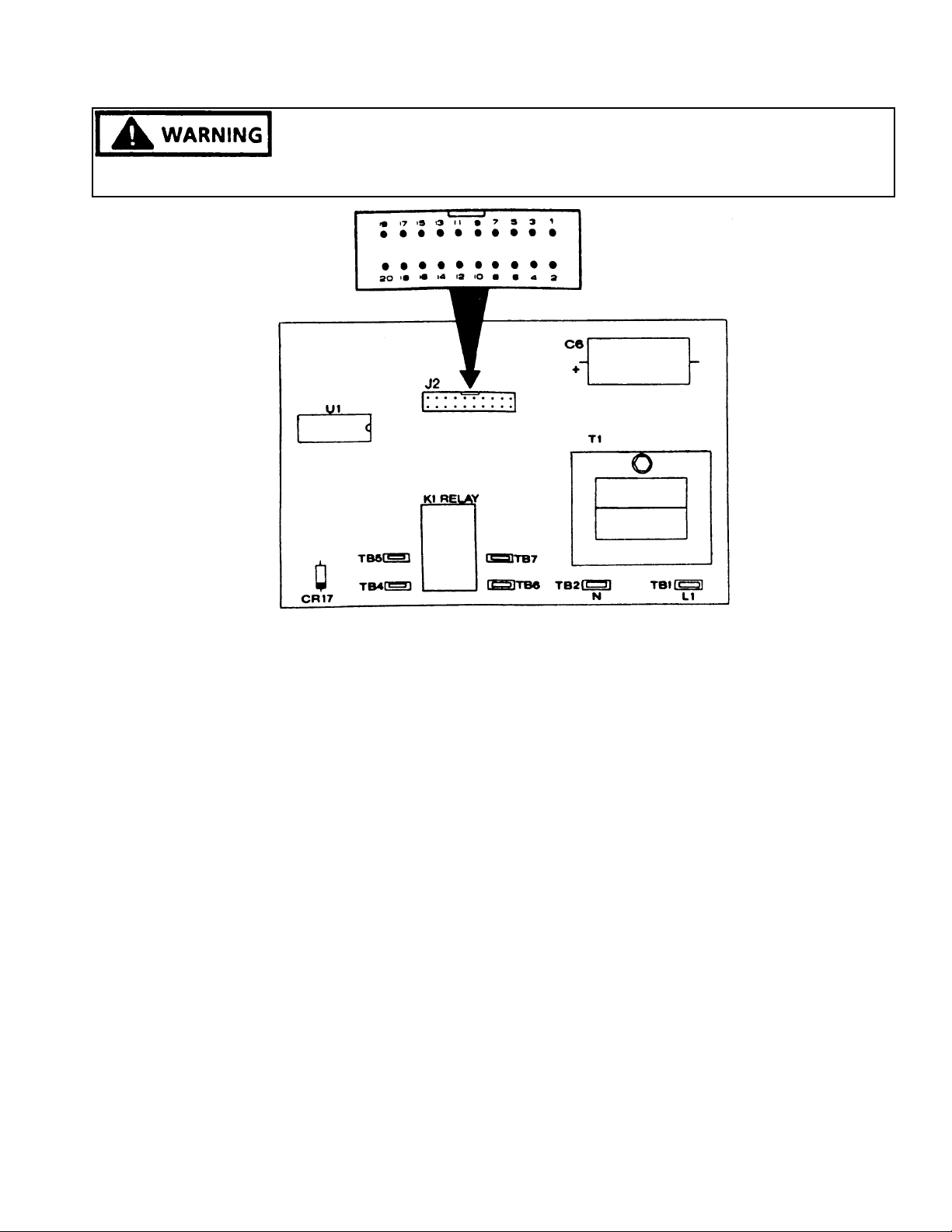
OPERATION AND SERVICE PROCEDURES
(SLIDE IN MODELS)
TO AVOID THE RISK OF ELECTRIC SHOCK, PERSONAL INJURY OR DEATH DISCONNECT POWER
BEFORE SERVICING, UNLESS TESTING REQUIRES IT.
Figure 57 - Clock/Timer P.C. Board
5. Set the Cook/Clean time for one (1) minute by pressing the "COOK/CLEAN TIME" button ("0:00" will be
displayed) and then pressing the "UP" button one
time ("0:01" should be displayed). After a short delay
the TB4 - TB5 contact should close (zero ohms),
"AUTO" and the oven indicator symbol should appear
on the left and center of the display, and the Time-ofDay will appear on the digital display. When the one
(1) minute Cook/Clean time elapses, the TB4 - TB5
contact should open (infinite ohms), an alarm will
sound for approximately ten (10) seconds and the
oven indicator symbol in the center of the display will
turn off. "AUTO" will continue to blink ON and OFF
to indicate that the Clock/Timer was programmed for
a timed operation. Press the "CANCEL/CLOCK"
button to turn off the blinking "AUTO" display.
6. Press the "STOP TIME" button and enter the stop
time for two (2) minutes past the time of day. EX-
AMPLE: Set the Time-of-Day to 12:00.
Press the "STOP TIME" button (the display will
continue to show the Time-of-Day), then press the
"UP" button until "12:02" is displayed.
After a short delay, contact TB4 - TB5 should close
(continuity) and the display will show the Time-of-Day
along with the oven indicator in the center of the
display and "AUTO" on the left of the display.
When the stop time is reached, the TB4 - TB5 contact
should open (infinite ohms), the oven indicator in the
center of the display turns off, and an alarm will sound
approximately ten (10) seconds. "AUTO" will continue to flash ON and OFF to designate that the Clock/
Timer was programmed for a timing function. Press
the "CANCEL/CLOCK" button to turn off the flashing
"AUTO" display.
7. Connnect the ohmmeter leads to terminals TB6 and
TB7 and repeat Steps 4 - 6 to test the other K1 relay
contact.
CLOCK P.C. BOARD VOLTAGE TESTS
Extreme caution must be taken when performing any live
voltage tests to avoid the possibility of electrical shock or
damage to the range components and/or testing equipment.
1. Shut off power to the range and disconnect the wire
leads from the P.C. board terminals L1 (TB1) and N
(TB2) to check the input voltage. Using a voltmeter
27 RC231002 Rev. 3
Page 29
OPERATION AND SERVICE PROCEDURES
(SLIDE IN MODELS)
TO AVOID THE RISK OF ELECTRIC SHOCK, PERSONAL INJURY OR DEATH DISCONNECT POWER
BEFORE SERVICING, UNLESS TESTING REQUIRES IT.
set to read 120 VAC or higher, attach the meter leads
to the L1 and N wire leads and turn on power to the
range. A voltage reading of approximately 120 VAC
should be indicated. If no voltage is indicated, check
the range wiring. If 120 VAC is indicated shut off
power to the range and reconnect L1 and N wire leads
to the P.C. board terminals.
2. Disconnect the 20 pin ribbon cable connector from
the P.C. board J2 connector and turn on the power to
the range. Check for voltages at the following pins at
the J2 connector. (See Figure 28.)
PINS VOLTAGE
2-18 -25 to -35 VDC
6-18 -7 to -9 VDC
8-18 -7 to -9 VDC
10-18 -7 to -9 VDC
14-18 -25 to -35 VDC
15-18 -25 to -35 VDC
2-14 2.0 to 3.6 VDC
DISPLAY BOARD TESTING
Shut off power to the range and remove the display board
from the control panel (refer to Disassembly Procedures).
The function switches and diodes on the display board can
be checked at the J1 connector. Install the clock control
buttons into the display board switch housings. Refer to
Figure 30 for the correct pin number identification.
1. To check the "MINUTE TIMER" switch and CR3
diode, connect an ohmmeter (set to RX10 or higher)
to pins 8 and 17 at the display board J1 connector and
press the minute timer button. Reverse the ohmmeter leads and again press the "MINUTE TIMER"
button. On reading should indicate infinite ohms and
the other reading should indicate low ohms (the diode
conduction resistance and closed minute timer switch).
If a zero (0), low or infinite ohms reading is indicated
with the meter leads connected in both directions, the
display board should be replaced.
2. To check the "COOK/CLEAN TIME" switch and the
CR5 diode, connect the ohmmeter leads to pins 10
and 16 at the display board J1 connector and press
the "COOK/CLEAN TIME" button. Reverse the meter
leads and again press the "COOK/CLEAN TIME"
button. One reading should indicate infinite ohms
and the other reading should indicate low ohms (the
diode conduction resistance and closed "COOK/
RC231002 Rev. 3 28
CLEAN TIME" switch). If a zero, low, or infinite ohms
reading is indicated with the meter leads connected in
both directions, the display board should be replaced.
3. To check the "STOP TIME" switch and the CR5
diode, connect the ohmmeter leads to Pins 6 and 16
at the display board J1 connector and press the
"STOP TIME" button. Reverse the meter leads and
again press the "STOP TIME" button. One (1)
reading should indicate infinite ohms and the other
reading should indicate low ohms (the diode conduction resistance and closed STOP TIME switch). If a
zero (0), low or infinite ohms reading is indicated with
the meter leads connected in both directions, the
display board should be replaced.
4. To check the "UP" switch and the CR4 diode, connect
the ohmmeter leads to Pins 8 and 20 at the display
board J1 connector and press the "UP" button. Reverse the meter leads and again press the "UP"
button. One reading should indicate infinite ohms
and the other reading should indicate low ohms (the
diode conduction resistance and closed "UP" switch).
If a zero (0), low, or infinite ohms reading is indicated
with the meter leads connected in both directions, the
display board should be replaced.
5. To check the "DOWN" switch and the CR4 diode,
connect the ohmmeter leads to Pins 6 and 20 at the
display board J1 connector and press the "DOWN"
button. Reverse the meter leads and again press the
"DOWN" button. One reading should indicate infinite
ohms and the other reading should indicate low ohms
(the diode conduction resistance and closed "DOWN"
switch). If a zero (0), low, or infinite ohms reading is
indicated with the meter leads connected in both
directions, the display board should be replaced.
6. To check the "CLOCK/CANCEL" switch and the CR2
and CR4 diodes, connect the ohmmeter leads to Pins
10 and 20 at the display board J1 connector and press
the "CLOCK/CANCEL" button. Reverse the meter
leads and again press the "CLOCK/CANCEL" button.
One reading should indicate infinite ohms and the
other reading should indicate low ohms (CR2 and
CR4 diode conduction resistance and closed "CLOCK/
CANCEL" switch). If a zero (0), low, or infinite ohms
reading is indicated with meter leads connected in
both directions, the display board should be replaced.
7. The CR1 diode can be checked by connecting the
Page 30
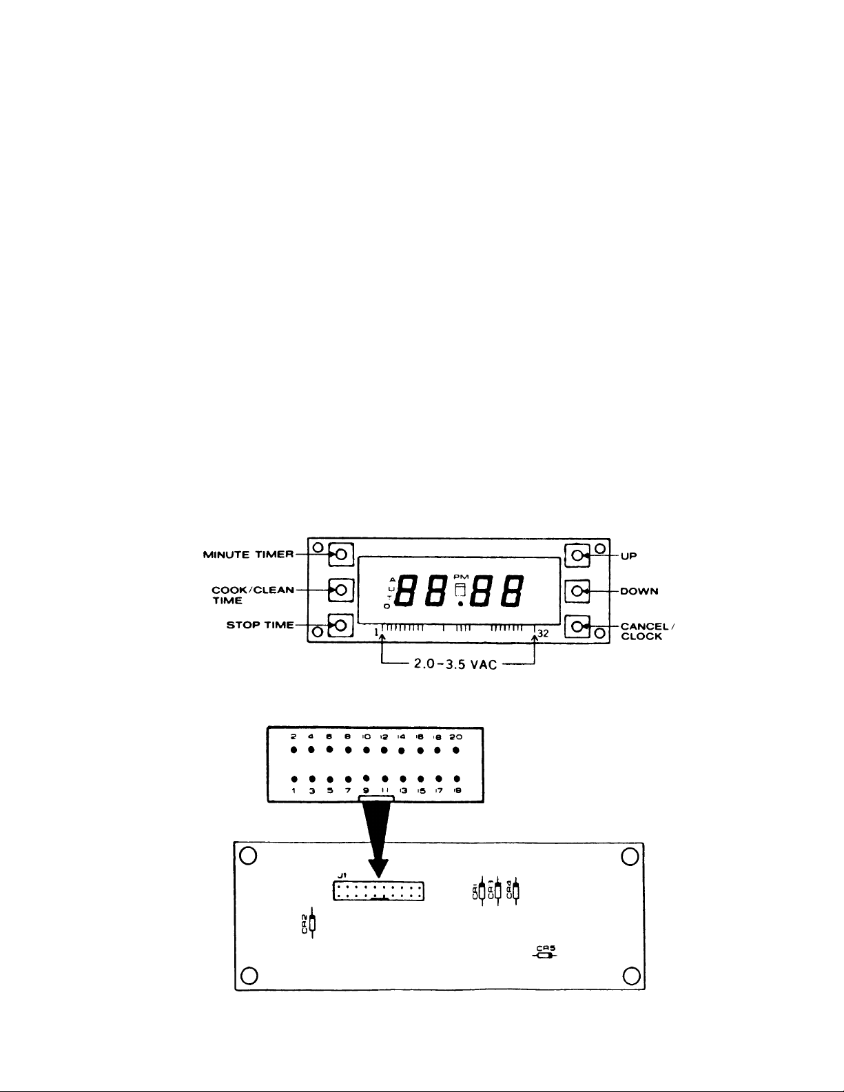
OPERATION AND SERVICE PROCEDURES
(SLIDE IN MODELS)
ohmmeter leads to Pins 10 and 17 at the display board
J1 connector and then reversing the ohmmeter leads.
One reading should indicate infinite ohms and the
other reading should indicate low ohms (CR1 diode
conduction resistance). If a zero (0), or infinite ohms
reading is indicated with the meter leads connected in
both directions, the display board should be replaced.
P.C. BOARD/DISPLAY BOARD
INTERCONNECT CABLE
The 20 pin ribbon cable that connects the Clock/Timer P.B.
board to the display board can be checked for continuity
using an ohmmeter set to the low ohms scale. Refer to
Figure 29 and 30 for correct pin identification. If an open
wire is indicated in the ribbon cable, the cable should be
replaced.
The information on Page 54 pertains to the 20 wire ribbon
cable which connects the P.C. board to the display board.
A switch was added to each wire of the ribbon cable to
demonstrate the results if that switch/wire opened. This
information may be useful in diagnosing and repairing
some display/control problems on the digital clock/timer.
Figure 58 - Display Board
Figure 59 - Display Board - Rear View
29 RC231002 Rev. 3
Page 31

OPERATION AND SERVICE PROCEDURES
(SLIDE IN MODELS)
1 through 20 below represent the 20 Wire Ribbon Cable
connecting the Clock/Timer P.C. Board to the Display
Board and Circuit/Operation failure mode or result if an
individual Wire/Circuit is Open.
EXAMPLE: No "STOP TIME" or "DOWN" Programming
Operations. Look for an open number 6 wire in ribbon
cable.
RC231002 Rev. 3 30
Page 32

TROUBLESHOOTING GUIDE
a
s
e
s
k
a
O
m
ccept
s
o
gramme
d
e
P
eplace
(SLIDE IN MODELS)
PROBLEMS POSSIBLE CAUSE CORRECTION
Erratic Display Or No
Display
Clock/Timer Does Not
Respond when a
Pushbutton is Pressed
No Voltage to Clock/Timer P.C.
Board
Defective Clock/tim er P.C.
Board
Defective P.C. Board to Display
Board Interconnect Cable
No Voltage to Display Board
Defective Interco nnect Cable
Defective Display Board
Defective P.C. Board
Check for 120 VAC at P.C. bo
TB1 and TB2. If no voltage i
wiring.
Disconnect ribbon cable from
voltages at P.C. board 20 pin
incorrect voltages are indicat
Check interconnect cable for
replace cable.
Check for 2.0 - 3.5 VAC at di
no voltage is indicated, chec
Board.
Check interconnect cable for
replace cable.
Check display board function
defective, replace display bo
If interconnect cable and disp
P.C. board.
Beeper Does Not Sound
When Control Function
Buttons Are Pressed.
Time-of-Day Clock and
Timing Functions Operate
Normally.
Time-of-Day Display in
Military Tim e.
Oven Does Not Heat In
Timer Bake or Self-Clean
Timed Modes. Clock/Tim er
A
Pr
Tim
Defective P.C. Board Replace the P.C. Board.
Not a Problem. This is a Feat ure
of the Clock/Timer
Defective P.C. Board Check K1 relay contacts on
Press "COOK" time and "ST
simultaneously to set clock ti
shut off power to unit, wait (5)
contacts not closing, replace
R
Wiring.
31 RC231002 Rev. 3
Page 33

OPERATION AND SERVICE PROCEDURES
Electronic Range Control (ERC) (Models w/Two Piece Control)
NOTE: Two (2) piece control system - clock timer in
backguard - relay board back bottom of range.
The Electronic Range Control (ERC) controls all thermostat, selector switch, and clock timing functions for BAKE,
TIMED BAKE, BROIL, and SELF-CLEAN operations. The
ERC also has a minute timer function which can time an
operation up to nine (9) hours and fifty (50) minutes. The
minute timer does not control the oven operation.
Figure 35 - Electronic Range Control - ERC
To Set Time of Day:
1. Press the "CLOCK" button. "TIME" will appear on the
left side of the display.
2. Rotate the "TIME/TEMP. SET" knob to the desired
time of day.
3. Press the "SET/CANCEL" button to initiate the time of
day clock. "TIME" will go out on the left side of the
display. NOTE: If the "SET/CANCEL" button is not
pressed after the desired time of day is set, the ERC
will automatically initiate the time of day after a short
period of time.
tion. If the timer function is not cancelled, the alarm
will sound approximately once every ten (10) seconds
to remind you to cancel the minute timer function.
To cancel the minute timer function while the timer is
still counting down, simply rotate the "TIME/TEMP.
SET" knob counterclockwise until ":00" is displayed.
The ERC will automatically cancel the timer function.
To Use the Bake Function:
1. Press the "BAKE TEMP" button. "BAKE" will appear
along with the along with the three (3) center horizontal segments and the degree symbol in the temperature display.
2. Rotate the "TIME/TEMP. SET" knob to the desired
baking temperature from 170°F. to 550°F. The
display will increase in 5° increments starting with
170°. The ERC will automatically initiate the bake
operation approximately two (2) seconds after the
last temperature entry and "ON" will appear in the
display. The oven temperature rise will be displayed
during oven preheat in 5° increments starting at
100°F.
To cancel the bake function, simply press the "SET/
CANCEL" button or rotate the "TIME/TEMP. SET"
knob counterclockwise until the temperature display
shows the three (3) center horizontal segments and
the degree symbol. The ERC will then automatically
cancel the bake function.
To Use the Cook Time Function:
To Set Minute Timer:
1. Press the "MINUTE TIMER" button. "TIMER" and
":00" will appear on the display.
2. Rotate the "TIME/TEMP. SET" knob clockwise to set
the desired timing period up to nine (9) hours and fifty
(50) minutes. The display will increment in 5, 10, 60
second and five (5) and ten (10) minute increments.
The ERC will automatically initiate the timer countdown two (2) seconds after the last entry. The timer
will count down in seconds if the entered time is one
(1) hour or less. If the entered time is more than one
(1) hour, the timer will count down in minutes until
reaching one (1) hour on the display, then the timer
will count down in seconds for the remaining time.
When the timer counts down to ":00", an alarm will
sound three (3) times to indicate the timing function
is completed. Press the "MINUTE TIMER" button or
the "SET/CANCEL" button to cancel the timer func-
RC231002 Rev. 3 32
1. Press the "COOK TIME" button. "TIME", "OVEN",
AND ":00" will be displayed.
2. Rotate the "TIME/TEMP. SET" knob clockwise to set
the desired amount of cooking time up to eleven (11)
hours and fifty-five (55) minutes. The display will
increase in five (5) and ten (10) minute increments.
3. Press the "BAKE TEMP" button. "BAKE" will appear
along with the three (3) center horizontal segments
and the degree symbol in the temperature display. If
the "BAKE TEMP" button is not pressed within approximately five (5) seconds after setting the cook
time, an alarm will sound to remind you to set the bake
temperature.
4. Rotate the "TIME/TEMP. SET" knob clockwise to the
desired baking temperature from 170°F. to 550°F.
The display will increase in 5° increments starting
from 170°. The ERC will automatically initiate the
timed cook function approximately two (2) seconds
Page 34

OPERATION AND SERVICE PROCEDURES
Electronic Range Control (ERC) (Models w/ Two Piece Control)
after the last temperature entry and "ON" will appear
on the display. The oven temperature rise will be
displayed during oven preheat in 5° increments starting at 100°F. When the timed cook function is
completed the ERC will automatically turn the oven
off and an alarm will sound three (3) times. The
display will then show the time of day.
To change the cook time or baking temperature while
the oven is operating in the timed cook function,
simply press the appropriate button for the function to
be changed (COOK TIME or BAKE TEMP) and then
rotate the "TIME/TEMP. SET" knob to set the new
time or temperature.
To cancel the timed cook function before it is completed, simply press the "SET/CANCEL" button or
rotate the "TIME/TEMP. SET" knob counterclockwise until cooking time display shows ":00", or until
the temperature display shows the three (3) center
horizontal segments and the degree symbol. The
ERC will then automatically cancel the timed cook
function.
To Use the Stop Time Function:
be changed (STOP TIME or BAKE TEMP.) and then
rotate the "TIME/TEMP. SET" knob to set the new
stop time or temperature.
To cancel the stop time function before it is completed, simply press the "SET/CANCEL" button.
To Use Stop Time for Delayed Baking Function:
1. Press the "STOP TIME" button. "STOP TIME" and
the current time of day will be displayed.
2. Rotate the "TIME/TEMP. SET" knob clockwise to the
time the oven should turn off. The display will
increase in five (5) minute increments.
3. Press the "COOK TIME" button. "OVEN", "TIME",
and the "CALCULATED COOK TIME" will be displayed.
4. Rotate the "TIME/TEMP. SET" knob to enter the
amount of time to bake. The display will decrease in
five (5) or ten (10) minute decrements depending on
the programmed stop time and the time of day.
"DELAY" will appear on the display.
1. Press the "STOP TIME" button. "STOP TIME" will
appear in the display.
2. Rotate the "TIME/TEMP. SET" knob clockwise to set
the desired stop time or time the oven is to shut off,
up to eleven (11) hours and fifty-nine (59) minutes
after the time of day depending on the current time of
day programmed into the ERC. The display will
increase in five (5) minute increments.
3. Press the "BAKE TEMP" button. "BAKE" will appear
along with the three (3) center horizontal segments. If
the "BAKE TEMP" button is not depressed within
approximately five (5) seconds after setting the stop
time, an alarm will sound to remind you to set the bake
temperature.
4. Rotate the "TIME/TEMP. SET" knob to set the desired baking temperature from 170°F. to 550°F. The
display will increase in 5° increments starting from
170°F. The ERC will automatically initiate the baking
function approximately two (2) seconds after the last
temperature entry and "ON" will appear in the display.
The oven will operate until the stop time is reached.
At that time the ERC automatically turns the oven off
and an alarm will sound three (3) times. The display
will then show the time of day.
To change the stop time or the baking temperature
while the oven is operating in the stop time function,
simply press the appropriate button of the function to
33 RC231002 Rev. 3
5. Press the "BAKE TEMP." button. "BAKE" will appear
along with three (3) center horizontal segments and
the degree (°) symbol in the temperature display. If
the "BAKE TEMP" button is not pressed within approximately five (5) seconds after setting the cook
time an alarm will sound as a reminder to set the bake
temperature.
6. Rotate the "TIME/TEMP. SET" knob to the desired
baking temperature from 170°F. to 550°F. The ERC
will automatically calculate the start time. When the
start time is reached, "DELAY" will turn off and "ON"
will appear. The oven will then operate until the stop
time is reached. The ERC will then automatically turn
the oven off, an alarm will sound three (3) times and
":00" will be displayed.
7. Press the "SET/CANCEL" button to cancel the timed
function.
To Set Broil Function:
1. Press the "BROIL" button. "BROIL" will appear along
with three (3) center horizontal segments in the
temperature display.
2. Rotate the "TIME/TEMP. SET" knob clockwise to set
the broil function to either "LO" (approximately 460°
F.) or "HI" (approximately 560°F.). The ERC will
automatically initiate the broil function approximately
two (2) seconds after setting the "LO" or "HI" entry and
Page 35

OPERATION AND SERVICE PROCEDURES
Electronic Range Control (ERC) (Models w/Two Piece Control)
"ON" will appear in the display.
To change the broil setting while the oven is operating
in the broil mode, simply rotate the "TIME/TEMP
SET." knob to change the setting. The ERC will
automatically initiate the new broil function approximately two (2) seconds after setting the new entry.
To cancel the broil function, simply press the "SET/
CANCEL" button or rotate the "TIME/TEMP. SET"
knob counterclockwise until the three (3) center horizontal segments appear on the temperature display.
The ERC will then automatically cancel the broil
function.
To Set for Self-Clean:
1. Move the door lock lever to the far right or locked
position.
2. Press the "CLEAN" button. "CLEAN" will appear
along with "3:00" in the display indicating a three (3)
hour cleaning time. The ERC will automatically
initiate the clean function approximately two (2) seconds after the "CLEAN" button is pressed. If the door
lock lever is not moved to the locked position prior to
pressing the "CLEAN" button, "DOOR" will be displayed and an alarm will sound as a reminder to lock
the door. The "LOCK" light will be displayed approximately ten (10) to twenty (20) minutes into the clean
cycle and remain on after the completion of the clean
cycle. At the completion of the clean cycle the time
of day will be displayed along with the "LOCK" light.
The "LOCK" light will turn off when the oven temperature is at a safe level to open the door.
3. Allow the oven to cool approximately twenty (20) to
thirty (30) minutes before trying to move the door lock
lever to the open position. DO NOT FORCE THE
LOCK LEVER. If the door lock will not open, wait five
(5) minutes and try again. NOTE: The "LOCK" light
and actual door latch locking/unlocking temperatures
are not calibrated with each other, i.e., the door lock
may be opened before the "LOCK" light turns off or
vice versa.
To Set for Delayed Self-Clean:
1. Move the door lock lever to the far right or locked
position.
2. Press the "STOP TIME" button. "STOP TIME" and
the current time of day will be displayed.
3. Rotate the "TIME/TEMP. SET" knob clockwise to set
the desired time the oven is to turn off.
4. Press the "CLEAN" button. "DELAY", "CLEAN", and
"TIME" will appear along with "3:00" in the display
indicating a three (3) hour cleaning time. If the door
lock lever is not moved to the lock position prior to
pressing the "CLEAN" button. "DOOR" will be displayed and an alarm will sound as a reminder to lock
the door. The ERC will automatically calculate the
start time.
EXAMPLE: If the current time of day is 12:00, to
operate the oven in a clean function which will end at
5:00, (1) lock the oven door, (2) set the stop time for
5:00 and, (3) press the "CLEAN" button. The ERC will
start the cleaning function at 2:00 and turn the oven
off at 5:00.
When the start time is reached, "DELAY" will turn off,
"ON" will appear, and the ERC will initiate the clean
cycle. The "LOCK" indicator will be displayed approximately 10-20 minutes into the clean cycle and
remain on after the completion of the clean cycle.
When the stop time is reached, the ERC will automatically turn the oven off and the time of day and
"LOCK" will be displayed. "LOCK" will remain displayed until the oven temperature is at a safe level to
open the door.
5. Allow the oven to cool approximately twenty (20) to
thirty (30) minutes before trying to move the door lock
lever to open the door. DO NOT FORCE THE LOCK
LEVER. If the door lock will not open, wait five (5)
minutes and try again. NOTE: The "LOCK" light and
actual door latch locking/unlocking temperatures are
not calibrated with each other, i.e., the door lock may
be opened before the "LOCK" light turns off or vice
versa.
To Use Cancel Function:
1. Pressing the "SET/CANCEL" button will cancel all
cooking, cleaning, or timing functions except the
minute timer function. The display will return to the
time of day unless a minute timer operation is present.
2. To display the time of day during a program, press the
"CLOCK" button. The display will return to the time
of day. To view the remaining time on a program after
returning the display to the time of day, simply press
the appropriate function button ("MINUTE TIMER",
"STOP TIME", "COOK TIME", or "CLEAN" button).
The display will then show the remaining program
time.
ELECTRONIC RANGE CONTROL - ERC
RC231002 Rev. 3 34
Page 36

OPERATION AND SERVICE PROCEDURES
Electronic Range Control (ERC) (Models w/ Two Piece Control)
TO AVOID THE RISK OF ELECTRIC SHOCK, PERSONAL INJURY OR DEATH DISCONNECT POWER
BEFORE SERVICING, UNLESS TESTING REQUIRES IT.
ERC SYSTEM EXPLANATION
THE ELECTRONIC RANGE CONTROL - ERC - operates
in conjunction with a remote relay/power supply circuit
board and an oven temperature sensor to control all bake,
timed bake, broil, and self-clean functions.
The ERC has eight (8) function buttons to control minute
timer, clock, stop time, bake, timed bake, broil, clean and
set/cancel operations, and a rotary dial to set time and
temperature.
The ERC display consists of two (2) digital readouts which
display the time of day, cooking time, cleaning time,
minute timer time, stop time, baking temperature, lo/hi
broil and failure codes as well as several indicators to show
which function the ERC is controlling.
The relay/power supply circuit board consists of two (2)
relays for bake and broil operations which are controlled by
the ERC, and a step down transformer with two (2) secondary windings which convert the 120 VAC input to 3.2 VAC
filament voltage to power the ERC display and 20.3 VAC
drive voltage which the ERC uses to turn on the bake and
broil relays.
The oven temperature sensor is mounted in the oven
cavity and is connected to the J2 connector on the rear of
the ERC. As the oven temperature increases, the sensor
resistance also increases. The ERC converts this resistance change to a corresponding temperature readout.
The ERC then cycles the bake/broil relays to maintain the
desired temperature setting.
The ERC is also capable of sensing certain failure conditions which can occur in the temperature sensor, the selfclean latch switch or the ERC itself. If the ERC senses a
failure, power will be removed from the bake/broil relays,
an alarm will sound, and a failure code will be displayed.
Each major component of the Electric Range Control
System (ERC, temperature sensor, or relay/power supply
circuit board) is serviced as a separate part. However,
each component and related wire harness must be tested
prior to replacing an individual component.
NOTE: Clock must previously be set for the time of day.
1. Press and hold the "CLOCK" button until "TIME" is
displayed and until "TIME" turns off.
2. Momentarily press "CANCEL" button until all display
segments are lit. Following the lighting of all of the
segments, the display will go through a "SALES
DEMONSTRATION" mode, displaying individual functions. The "SALES DEMONSTRATION" mode will
show: (1) "BROIL", three (3) horizontal segments and
the degree symbol, (2) "OVEN" "TIME" and ":00" , (3)
"CLEAN", "TIME" and "3:00" (4) "TIMER" and ":00",
(5) time of day, (6) all segments, and (7) "BAKE",
three (3) horizontal segments and the degree symbol.
The program will continue to repeat until the "CANCEL" button is pressed. The time of day should then
be displayed.
RELAY/POWER SUPPLY CIRCUIT BOARD TESTING
Testing with No Voltage Applied
The relay/power supply circuit board transformer windings,
relay windings, and relay contacts can be checked as
follows:
1. Shut off power to the appliance.
2. Disconnect the J1 connector from the circuit board.
Also remove the wire leads from the circuit board
terminals E1 through E7. Using an ohmmeter, check
for the following readings in Table 1 below. Refer to
Figure 22 for correct terminal/pin location. Figure 23
shows the relay/power supply circuit board schematic.
TESTING PROCEDURES
"DISPLAY" MODE - All segments of the display can be
checked by using the following sequence:
35 RC231002 Rev. 3
Page 37

OPERATION AND SERVICE PROCEDURES
Electronic Range Control (ERC) (Models w/Two Piece Control)
TO AVOID THE RISK OF ELECTRIC SHOCK, PERSONAL INJURY OR DEATH DISCONNECT POWER
BEFORE SERVICING, UNLESS TESTING REQUIRES IT.
NOTE: Check each transformer terminal (J1-5, J1-6, J1-
TERMINALS
7, J1-8, E1 and E2) in turn to ground terminal E3. All
/PINS
readings must be infinite (OPEN).
J1-1 TO J1-2
J1-1 TO J1-3
J1-5 TO J1-6
J1-7 TO J1-8
E1 TO E2
E4 TO E5
E6 TO E7
BAKE RELAY COIL
BROIL RELAY COIL
TRANSFORM ER SECONDARY WINDIN G
TRANSFORM ER SECONDARY WINDIN G
TRANSFORMER PRI MARY WINDING
BROIL RELAY CONTACT
BAKE RELAY CO NTAC T
CIRCUIT TESTED
560 OHMS
560 OHMS
5-7 OHMS
2-4 OHMS
120-150 OHMS
INFINITE OHMS (OPEN)
INFINITE OHMS (OPEN)
APPROXIMATE
OHMS READINGS
Figure 36
Relay/Power Supply Circuit Board
Terminal/Pin Locations
Figure 37
Relay Board Schematic
RC231002 Rev. 3 36
Page 38

OPERATION AND SERVICE PROCEDURES
Electronic Range Control (ERC) (Models w/ Two Piece Control)
TO AVOID THE RISK OF ELECTRIC SHOCK, PERSONAL INJURY OR DEATH DISCONNECT POWER
BEFORE SERVICING, UNLESS TESTING REQUIRES IT.
Testing with Voltage Applied
The relay/power supply circuit board voltages can be
tested by following the procedures below. Caution should
always be taken when making live voltage tests to avoid
electrical shock and/or damage to range components or
test equipment.
1. To check the input supply voltage to the transformer
primary winding, shut off power to the range and
connect your AC voltmeter to terminals E1 and E2.
Turn on power to the range. A voltage reading of
approximately 108-132 VAC should be indicated. If
a low voltage or no reading is indicated, check for
loose connections or broken wiring.
2. To check the transformer secondary winding output
(filament) voltage, shut off power to the range and
insert your AC voltmeter leads into the J1 connector
at pins J1-7 and J1-8 and turn on power to the
appliance. A voltage reading of approximately 3.2
VAC should be indicated. If no voltage is indicated,
recheck primary input voltage (Step 1). If primary
input voltage checks good, replace the relay/power
supply board.
5. To check the broil relay drive voltage supplied to the
relay/power supply board from the ERC, shut off
power to the range and insert your DC voltmeter leads
into the J1 connector at pins J1-3 and J1-1 and turn
on power to the range. With no bake or broil operation
programmed into the ERC, zero (0) VDC should be
indicated. Program the ERC for a broil operation.
When the ERC initiates the broil program, a voltage
reading of approximately 24 VDC should be indicated. If no voltage is indicated, check for loose
connections or broken wiring, and also for drive
voltage at the ERC J1 connector at pins J1-8 and J1-
5.
6. To check the bake relay contacts, shut off power to
the range and attach your AC voltmeter leads to the
relay board terminals E6 and E7 and turn on power to
the range. A voltage reading of approximately 120
VAC should be indicated. Program the ERC for a
bake operation.
When the ERC initiates the bake function, the voltage
reading should drop to zero (0) VAC. If the voltage
does not drop to zero (0) VAC, the relay is not being
energized or the relay is defective.
3. To check the transformer secondary winding output
voltage (used to drive relays), shut off power to the
range and insert your AC voltmeter leads into the J1
connector at pins J1-6 and J1-5 and turn on power to
the appliance. A voltage reading of approximately
20.3 VAC should be indicated. If no voltage is
indicated, recheck primary input voltage (Step 1). If
primary input voltage checks good, replace the relay/
power supply board.
4. To check the bake relay drive voltage supplied to the
relay/power supply board from the ERC, shut off
power to the range and insert your AC voltmeter leads
into the J1 connector at pins J1-2 and J1-1 and turn
on power to the range. With no bake operation
programmed into the ERC, zero (0) VDC should be
indicated. Program the ERC for a bake operation.
When the ERC initiates the bake program, a voltage
reading of approximately 24 VDC should be indicated. If no voltage is indicated, check for loose
connections or broken wiring, and also for drive
voltage at the ERC J1 connector at pins J1-9 and J1-
5.
37 RC231002 Rev. 3
7. To check the broil relay contacts, shut off power to the
range and attach your AC voltmeter leads to the relay
board terminals E4 and E5 and turn on power to the
range. A voltage reading of approximately 120 VAC
should be indicated. Program the ERC for a broil
operation. When the ERC initiates the broil function,
the voltage reading should drop to zero (0) VAC. If the
voltage does not drop to zero (0) VAC, the relay is not
being energized or the relay is defective.
ERC OVEN TEMPERATURE SENSOR
The oven temperature sensor is mounted in the oven
cavity and electrically connected to the J2 connector, pins
1 and 3 on the rear of the ERC. The sensor resistance
changes with temperature changes inside the oven cavity
and the ERC controls the oven temperature by reacting to
the sensor resistance changes.
The sensor resistance can be checked by removing the
sensor interconnect harness plug from the ERC J2 connector and inserting the ohmmeter leads into the harness
connector plug. A resistance reading of 1091 ± 5.5 ohms
should be indicated at ambient room temperature (75°F.)
Page 39

OPERATION AND SERVICE PROCEDURES
Electronic Range Control (ERC) (Models w/Two Piece Control)
TO AVOID THE RISK OF ELECTRIC SHOCK, PERSONAL INJURY OR DEATH DISCONNECT POWER
BEFORE SERVICING, UNLESS TESTING REQUIRES IT.
tests and Figure 37.) The sensor resistance can also
If a higher resistance is indicated disconnect the interconnect harness from the sensor and recheck the sensor
resistance to assure that the problem is in the sensor and
not in the interconnect harness or due to a bad connection.
The following table shows the corresponding resistance for
different oven temperatures.
SENSING ELEMENT
TEMPERTURE
SENSING
RESISTANCE
be checked by removing the J2 connector and inserting the ohmmeter leads into the connector plug
terminals.
6. To remove the ERC, disconnect the J1 and J2
connectors and remove the four (4) ERC mounting
screws.
ERC VOLTAGE TESTS
75°F 1091 ± 5.5 OHMS
350°F 1654 ± 11 OHMS
535°F 2018 ± 16 OHMS
875°F 2652 ± 24 OHMS
Figure 38 - E.R.C. Oven Temperature Sensor
ERC TROUBLESHOOTING FAILURE CODES AND
CALIBRATION
ERC REMOVAL
1. Shut off power to the range.
2. Remove the "TIME/TEMP. SET" knob by pulling it off
of the control shaft.
3. Remove the eight (8) function control buttons by
pulling them out of the ERC.
4. Remove the two (2) control panel lower trim mounting
screws. Carefully pull the lower trim and control panel
glass towards the front of the range and remove trim
and glass.
5. Remove the four (4) backguard control panel mounting screws (two (2) each side) and pull the panel
assembly forward. The ERC input and relay drive
voltages can now be tested at the ERC J1 connector
with power applied to the range. (See ERC voltage
RC231002 Rev. 3 38
1. Partially remove the ERC from the control panel.
Follow the ERC Removal Procedures, Steps 1 - 5.
2. To check the input voltage for the vacuum fluorescent
display, insert the AC voltmeter leads into the J1
connector at pins J1-1 and J1-2, and turn on power to
the range.
Figure 25 - Electronic Range Control Pin Identification
A voltage reading of approximately 3.2 VAC should
be indicated. If no voltage is indicated, check for
loose connections, open wire (s) and relay/power
supply circuit board output voltage at pins J1-7 and
J1-8 on the relay board.
3. To check the input voltage that the ERC uses to drive
the bake/broil relays, insert your AC voltmeter leads
into the J1 connector pins J1-3 and J1-4. A voltage
reading of approximately 20.3 VAC should be indicated. If no voltage or a low voltage is indicated,
check for the input supply voltage at pins J1-3 and J14 (Step 3).
4. To check the bake relay drive voltage, insert your DC
voltmeter leads into the J1 connector at pins J1-9 and
J1-5, and program the ERC for a bake operation.
Page 40

OPERATION AND SERVICE PROCEDURES
Electronic Range Control (ERC) (Models w/ Two Piece Control)
TO AVOID THE RISK OF ELECTRIC SHOCK, PERSONAL INJURY OR DEATH DISCONNECT POWER
BEFORE SERVICING, UNLESS TESTING REQUIRES IT.
When the ERC initiates the bake operations, a voltage reading of approximately 24 VDC should be
indicated. If no voltage is indicated, check for the
input supply voltage at pins J1-3 and J1-4 (Step 3).
5. To check the broil relay drive voltage, insert your DC
voltmeter leads into the J1 connector at pins J1-8 and
J1-5, and program the ERC for a broil operation.
When the ERC initiates the broil operation, a voltage
reading of approximately 24 VDC should be indicated. If no voltage is indicated, check for the input
supply voltage at pins J1-3 and J1-4 (Step 3).
Figure 40 - Electronic Range Control Rear View
39 RC231002 Rev. 3
Page 41

OPERATION AND SERVICE PROCEDURES
Electronic Range Control (ERC) (Models w/Two Piece Control)
ERC FAILURE CODES AND WARNINGS
The Electronic Range Control is capable of detecting
certain failures within the ERC, the oven temperature
sensor and the self-clean latch switch.
The failure codes and warnings which may appear on the
display include F1 through F8, "DOOR", or "LOCK". A brief
description of the failure codes and warnings is listed
below:
F1 - Indicates a failed component in the E.R.C.
F2 - Sensor resistance too high. Check sensor resistance,
wire harness, and connections.
F3 - Open wire lead in sensor harness, bad harness/
sensor connection or sensor resistance too high.
F4 - Sensor resistance too low (below 500 ohms). Check
for a short in sensor wire harness and check sensor
resistance.
F5 - Indicates a failed component in the ERC.
F6 - Indicates a failed component in the ERC or due to
fluctuations in 60 Hz power source.
F7 - Indicates a shorted or sticking contact in one or more
of the function control switches. Make sure the
function buttons are not binding on the control panel
glass - reposition the ERC and/or glass. Make sure
the function buttons spring outward after being de-
pressed.
F8 - Indicates a failed component in the ERC.
F9 - Door Latch Supervisory (Door latched):
Sounds alarm and resets control to non-cook mode if
the door latch supervisory logic fails for a sample
period of 2 seconds (while the door is latched).
Unlatching the door (if not locked) and Cancel Key
may reset the display code and audible. If the door is
locked (temp > 500°F) power must be removed until
the oven door can be unlatched.
ELECTRONIC RANGE CONTROL TEMPERATURE
CALIBRATION
The ERC incorporates ± 35°F. calibration capabilities.
Follow the procedures below to calibrate the ERC.
1. Press and release the "BAKE TEMP." function button.
2. Rotate the "TIME/TEMP. SET" knob clockwise until a
temperature between 500° - 550° is displayed. Quickly,
before the ERC initiates the bake function, press and
hold the "BAKE TEMP" function button. After approximately four (4) seconds, the display will show
"00" or the offset temperature that was previously
programmed into the ERC.
3. Rotate the "TIME/TEMP. SET" knob to show the
desired offset temperature in the display (up to ±
35°F. in 5° increments, "+" to set oven temperature
higher and "-" to reduce oven temperature. NOTE:
An accurate temperature test should be performed
before calibrating the ERC.
4. Press the "CLOCK" function button to enter the offset
temperature into the ERC. The calibration adjustment will remain programmed into the ERC even if
power is removed from the ERC or range. NOTE:
Self-clean temperatures are not affected by this
calibration.
If oven temperature testing reveals that a calibration
in excess of ±35°F. is required, the oven temperature
sensor, sensor wire harness, and wire harness/sensor
connections must be checked before replacing the
ERC. A resistive connection within the sensor harness will affect oven temperature.
"LOCK" LIGHT ON - If "LOCK" appears in the display
when the oven is not set in clean mode, the oven sensor
resistance is too high. Check sensor resistance, wire
harness, and connections.
"DOOR" APPEARS IN DISPLAY IN BAKE/BROIL MODE
- This is an indication of a defective latch switch or shorted
wire lead from the ERC pin J1-10 to ground, or door is
latched.
"DOOR" APPEARS IN DISPLAY DURING CLEAN MODE
- This is an indication of a defective latch switch or an open
wire lead, from the ERC pin J1 - 10 to ground, or that the
door latch has not been closed as required to initiate the
clean cycle.
RC231002 Rev. 3 40
Page 42

TROUBLE SHOOTING GUIDE
h
a
o
b
v
d
o
2
o
e
3
w
g
o
n
g
v
r
d
Electronic Range Control (ERC) (Models w/Two Piece Control)
TO AVOID THE RISK OF ELECTRIC SHOCK, PERSONAL INJURY OR DEATH DISCONNECT POWER
BEFORE SERVICING, UNLESS TESTING REQUIRES IT.
PROBLEMS PO SSIBL E CAUS E CORRECTION
A. Display flashes the
Time-of-Day
B. No Display - E.R.C.
totally inoperat ive
1.
Power failure.
2.
Intermittent connection
between E.R.C. and
relay/power supply board.
3.
Defective E . R.C.
1.
No power to range.
2.
No voltage to relay/power
supply circuit board.
3.
No seconday output drive
voltage from relay/power
supply circuit board.
4.
No input dri ve voltage to
E.R.C.
1. This is a normal conditio n w
Press the "CLOCK" button
Tighten loose connect i ons
wiring.
Replace E.R.C.
1.
Check house fuse or circuit
wall outlet or junction box.
Check for 120 VAC at relay/
2.
terminals E1 and E2. If no
range wiring. If voltage is in
3.
Check for secondary drive v
VAC) at relay board pins J1 indicated and Steps 1 and
relay/power supply circuit b
proceed to Step 4.
Check for input drive voltag
4.
and J1-4 (approximately 20.
indicated, check wiring bet
supply circuit board. If volta
Step 5.
If Steps 1-4 abov e check g
1.
Check for secondary output
relay/power supply circuit bo
(approximately 3.2 VA C). If
replace relay board. If volta
Step 2.
Check for f ilam ent volt age (a
2.
E.R.C. J1-1 and J2-2. If no
wiring between E.R.C. and
is indicated, proceed to Step
3.
If Steps 1 an d 2 check goo
C. No Display - Range still
operates in bake, broil,
clean functi ons.
5.
Defective E . R.C.
1.
No Secondary output
filament voltage from
relay/power supply circuit
board.
2.
No filament voltage to
E.R.C.
3.
Defective E . R.C.
41 RC231002 Rev. 3
Page 43

TROUBLE SHOOTING GUIDE
o
n
e
a
a
o
3
e
g
Electronic Range Control (ERC) (Models w/Two Piece Control)
TO AVOID THE RISK OF ELECTRIC SHOCK, PERSONAL INJURY OR DEATH DISCONNECT POWER
BEFORE SERVICING, UNLESS TESTING REQUIRES IT.
PROBLEMS POSSIBLE CAUSE CORRECTI ON
D. Dim Display - Range
may or may no t op erat e .
1.2.Low supply voltage to
range.
Low input voltage to
relay/power supply circuit
board.
3.
Low relay/power supply
secondary output voltages.
Low input vo ltages to
4.
E.R.C.
Defective E.R.C.
5.
1. Check input voltage at wall
should be 102 - 132 VAC). I
VAC, conta ct po we r co mpa
voltage checks good, proc
Check for 102 - 132 VAC at
terminals E1 and E2. If votl
connections to terminals E1
good, proceed to Step 3.
3. Check for 3.2 VAC at r elay/p
and J1-8, and for 20. 3 VAC
pins J1-5 and J1-6. If either
relay/power supply circuit b
proceed to Step 4.
Check for 3.2 VAC at E. R.C .
20.3 VAC at E.R.C. pi ns J1low, check f o r loose connec
voltages check good, proc
If Steps 1 through 5 check
RC231002 Rev. 3 42
Page 44

TROUBLE SHOOTING GUIDE
r
t
d
a
d
e
a
e
g
d
e
o
C
-
n
Electronic Range Control (ERC) (Models w/Two Piece Control)
TO AVOID THE RISK OF ELECTRIC SHOCK, PERSONAL INJURY OR DEATH DISCONNECT POWER
BEFORE SERVICING, UNLESS TESTING REQUIRES IT.
PROBLEMS POSSIBLE CAUSE CORRECTION
E. Display operates
normally. Bake or broil
relays do not operate.
1.2.Open ground wir e for E.R. C.
relay drive return or relay
board relay drive return.
No E.R.C. relay drive
voltage.
3.4.No relay drive voltage to
relay/power supply circuit
board.
Open bake/broil relay coil.
1. Check continuity of green gr
and relay/power supply boa
If no continuity, repair or rep
good, proceed to Step 2.
Check for 24 VDC drive vol
when E.R.C. is programme
Check bake relay drive votl
J1-5. Check broil relay drive
anf J1-5. If no vol tage is ind
voltage is indicated, procee
3. Check for 24 VDC relay driv
E.R.C. is programmed for b
bake relay drive voltage at r
Check broil relay drive volta
J1-2. Check broi l rel ay bo ar
no voltage is indicated proc
Check bake/broil relay coil f
wire leads from relay board t
ohmmeter to the terminals.
board terminals J1-1 and J1
relay board terminals J1-3 a
be approximately 560 ohms.
relay board.
43 RC231002 Rev. 3
Page 45

TROUBLE SHOOTING GUIDE
a
c
a
e
c
s
f
c
d
c
c
e
t
A
n
t
e
d
e
Electronic Range Control (ERC) (Models w/Two Piece Control)
TO AVOID THE RISK OF ELECTRIC SHOCK, PERSONAL INJURY OR DEATH DISCONNECT POWER
BEFORE SERVICING, UNLESS TESTING REQUIRES IT.
PROBLEMS POSSIBLE CAUSE CORRECTION
F. "DOOR" appears in
display when E.R.C. is
programmed for bake or
broil.
G. "LOCK" appears in
display when oven is
not programmed and at
room temperature.
H. Oven temperature
display does not
increment to set
temperature during
preheat. Oven element
operates but not cycle.
1.
Door latch is set to far right
or clean positon.
2.
Shorted door latch switch
wire or short ed latch switch.
3.
Defective E.R.C.
1.2.Oven temperature sensor
resistance too high.
Defective E.R.C.
Sensor resistance too low or
1.
not changing with
temperature rise.
1. Door latch should be set to f
bake or broil functions.
Check for short ed lat ch swit
ground. If continuity is indic
switch contacts to determin
switch). If no continuity is in
If Steps 1 and 2 above che
1.2.Disconnect temperature sen
sensor resistance. At room t
should be 109 1 ± 5.5 ohms.
indicated, replace sensor. I
check wire harness resistan
connections. Each harness
(0) ohms. If resistance is in
If wire harness and sensor
2.
If wire harness and sensor
replace the E.R.C.
1. Defective oven temperature
plug and attach ohmmeter l
Resistance at room tempera
approximately 1091 ohms.
using a hair dryer or heat gu
should increase with sensor
resistance does not increas
resistance increa se s pro cee
If sensor checks good in St
Defective E.R.C.
2.
RC231002 Rev. 3 44
Page 46

OPERATION AND SERVICE PROCEDURES
For the Electronic Range Control (ERC) (Models w/Two Piece Control)
TO AVOID THE RISK OF ELECTRICAL SHOCK, PERSONAL INJURY OR DEATH DISCONNECT POWER
BEFORE SERVICING, UNLESS TESTING REQUIRES IT.
Figure 41 - Bake/Timed Bake Circuit
Bake burner is cycled by RR1 (K2) relay which is controlled
by varying temperature sensor resistance.
Figure 43 - Lo/Hi Broil Circuit
Broil burner is cycled by RR2 (K3) relay which is controlled
by varying temperature sensor resistance.
Figure 42 - Clean Cycle - Phase I
Broil burner operates first 30 minutes of clean cycle.
Figure 44 - Clean Cycle - Phase II
Bake burner operates thirty (30) minutes into clean cycle.
Burner is cycled by RR1 (K2) relay which is controlled by
varying temperature sensor resistance.
45 RC231002 Rev. 3
Page 47

OPERATION AND SERVICE PROCEDURES
Electronic Range Control - ERC - (Models w/One Piece Control)
OPERATING INSTRUCTIONS FOR THE
ELECTRONIC RANGE CONTROL (ERC)
NOTE: One Piece Control
The Electronic Range Control (ERC) controls all thermostat, selector switch, and clock timing functions for BAKE,
TIMED BAKE, BROIL, and SELF-CLEAN operations. The
ERC also has a minute timer function which can time an
operation up to nine (9) hours and fifty (50) minutes. The
minute timer does not control the oven operation.
Figure 45 - Electronic Range Control - ERC
To Set Time of Day:
1. Press the "CLOCK" button. "TIME" will appear on the
left side of the display.
2. Rotate the "TIME/TEMP. SET" knob to the desired
time of day.
3. Press the "SET/CANCEL" button to initiate the time of
day clock. "TIME" will go out on the left side of the
display. NOTE: If the "SET/CANCEL" button is not
pressed after the desired time of day is set, the ERC
will automatically initiate the time of day after a short
period of time.
To Set Minute Timer:
1. Press the "MINUTE TIMER" button. "TIMER" and
":00" will appear on the display.
2. Rotate the "TIME/TEMP. SET" knob clockwise to set
the desired timing period up to nine (9) hours and fifty
(50) minutes. The display will increment in five (5),
ten (10), and sixty (60) second and five (5) and ten
(10) minute increments. The ERC will automatically
initiate the timer countdown two (2) seconds after the
last entry. The timer will count down in seconds if the
entered time is one hour or less. If the entered time
is more than one hour the timer will count down in
minutes until reaching one hour on the display, then
the timer will count down in seconds for the remaining
time.
When the timer counts down to ":00", an alarm will
sound three (3) times to indicate that the timing
RC231002 Rev. 3 46
function is completed. Press the "MINUTE TIMER"
button or the "SET/CANCEL" button to cancel the
timer function. If the timer function is not cancelled,
the alarm will sound approximately once every ten
(10) seconds as a reminder to cancel the minute timer
function.
To cancel the minute timer function while the timer is
still counting down, simply rotate the "TIME/TEMP.
SET" knob clockwise until ":00" is displayed. The
ERC will automatically cancel the timer function.
To Use the Bake Function:
1. Press the "BAKE TEMP." button. "BAKE" will appear
along with the three (3) center horizontal segments
and the degree (°) symbol in the temperature display.
2. Rotate the "TIME/TEMP. SET" knob to the desired
baking temperature from 170°F. to 550°F. The
display will increase in five (5°) increments starting
from 170°. The ERC will automatically initiate the
bake operation approximately two (2) seconds after
the last temperature entry and "ON" will appear in the
display. The oven temperature rise will be displayed
during oven preheat in 5°F. increments starting at
100°F.
To cancel the bake function, simply press the "SET/
CANCEL" button or rotate the "TIME/TEMP. SET"
knob counterclockwise until the temperature display
shows the three (3) center horizontal segments and
the degree (°) symbol. The ERC will then automatically cancel the bake function.
To Use the Cook Time Function:
1. Press the "COOK TIME" button. "TIME", "OVEN",
and ":00" will be displayed.
2. Rotate the "TIME/TEMP. SET" knob clockwise to set
the desired amount of cooking time up to eleven (11)
hours and fifty-five (55) minutes. The display will
increase in five (5) and ten (10) minute increments.
3. Press the "BAKE TEMP." button. "BAKE" will appear
along with the three (3) center horizontal segments
and the degree (°) symbol in the temperature display.
If the "BAKE TEMP." button is not pressed within
approximately five (5) seconds after setting the cook
time, an alarm will sound as a reminder to set the bake
temperature.
4. Rotate the "TIME/TEMP. SET" knob clockwise to the
desired baking temperature from 170°F. to 550°F.
Page 48

OPERATION AND SERVICE PROCEDURES
Electronic Range Control - ERC (Models w/One Piece Control)
The display will increase in 5° increments starting
from 170°F. The ERC will automatically initiate the
timed cook function approximately two (2) seconds
after the last temperature entry and "ON" will appear
on the display. The oven temperature rise will be
displayed during oven preheat in 5° increments starting at 100° F. When the timed cook function is
completed the ERC will automatically turn the oven
off and an alarm will sound three (3) times. The
display will then show the time of day.
To change the cook time or baking temperature while
the oven is operating in the timed cook function,
simply press the appropriate button for the function to
be changed (COOK TIME or BAKE TEMP.) and then
rotate the "TIME/TEMP. SET" knob to set the new
time or temperature.
To cancel the timed cook function before it is completed, simply press the "SET/CANCEL" button or
rotate the "TIME/TEMP. SET" knob counterclockwise until cooking time display shows ":00", or until
the temperature display shows the three (3) center
horizontal segments and the degree (°) symbol. The
ERC will then automatically cancel the timed cook
function.
To Use the Stop Time Function:
1. Press the "STOP TIME" button. "STOP TIME" will
appear in the display.
2. Rotate the "TIME/TEMP. SET" knob clockwise to set
the desired stop time or time the oven is to shut off up
to eleven (11) hours and fifty-nine (59) minutes after
the time of day depending on the current time of day
programmed into the ERC. The display will increase
in five (5) minute increments.
and an alarm will sound three (3) times. The display
will then show the time of day.
To change the stop time or baking temperature while
the oven is operating in the stop time function, simply
press the appropriate button of the function to be
changed (STOP TIME or BAKE TEMP.) and then
rotate the "TIME/TEMP. SET" knob to set the new
stop time or temperature. To cancel the stop time
function before it is completed, simply press the
"SET/CANCEL" button.
To Use Stop Time for Delayed Baking Function:
1. Press the "STOP TIME" button. "STOP TIME" and
the current time of day will be displayed.
2. Rotate the "TIME/TEMP. SET" knob clockwise to the
time the oven is to turn off. The display will increase
in five (5) minute increments.
3. Press the "COOK TIME" button. "OVEN", "TIME",
and the "CALCULATED COOK TIME" will be displayed.
4. Rotate the "TIME/TEMP. SET" knob to enter the
amount of time to bake. The display will decrease in
five (5) or ten (10) minute decrements depending on
the programmed stop time and the time of day.
"DELAY" will appear in the display.
5. Press the "BAKE TEMP." button. "BAKE" will appear
along with the three (3) center horizontal segments
and the degree (°) symbol in the temperature display.
If the "BAKE TEMP." button is not pressed within
approximately five (5) seconds after setting the cook
time an alarm will sound as a reminder to set the bake
temperature.
3. Press the "BAKE TEMP." button. "BAKE" will appear
along with the three (3) center horizontal segments
and the degree (°) symbol in the temperature display.
If the "BAKE TEMP." button is not depressed within
approximately five (5) seconds after setting the stop
time, an alarm will sound as a reminder to set the bake
temperature.
4. Rotate the "TIME/TEMP. SET" knob to set the desired baking temperature from 170°F. to 550°F. The
display will increase in 5° increments starting from
170°F. The ERC will automatically initiate the baking
function approximately two (2) seconds after the last
temperature entry and "ON" will appear in the display.
The oven will operate until the stop time is reached.
At that time the ERC automatically turns the oven off
47 RC231002 Rev. 3
6. Rotate the "TIME/TEMP. SET" knob to desired baking temperature from 170° to 550°F. The ERC will
automatically calculate the start time. When the start
time is reached, "DELAY" will turn off and "ON" time
is reached. The ERC will then automatically turn the
oven off, an alarm will sound three (3) times and ":00"
will be displayed.
7. Press the "SET/CANCEL" button to cancel the timed
function.
To Set Broil Function:
1. Press the "BROIL" button. "BROIL" will appear along
with three (3) center horizontal segments in the
temperature display.
Page 49

OPERATION AND SERVICE PROCEDURES
Electronic Range Control - ERC - (Models w/One Piece Control)
2. Rotate the "TIME/TEMP. SET" knob clockwise to set
the broil function to HI.
To cancel the broil function, simply press the "SET/
CANCEL" button or rotate the "TIME/TEMP. SET"
knob counterclockwise until the three (3) center horizontal segments appear on the temperature display.
The ERC will then automatically cancel the broil
function.
To Set for Self-Clean:
1. Move the door lock lever to the far right or latched
position. "LOCK" will appear on the display.
2. Press the "CLEAN" button. "CLEAN" will appear and
"----" will show on the display. Rotate the "TIME/
TEMP" knob four (4) detents clockwise and display
will indicate "3:00" hour cleaning time. This can be
changed from two (2) hours to four (4) hours depending on amount of soil in oven (three (3) hours is
preferable). "CLEAN" display will appear to end of
clean time selected. "LOCK" will appear until the door
is unlatched which should be twenty (20) to thirty (30)
minutes after "clean" display has turned off and oven
has cooled down.
3. After oven cool down move door lock lever to far left
or unlatched position. If door can not be unlatched
wait another five (5) minutes. DO NOT FORCE THE
LATCH AS DAMAGE MAY RESULT.
To Set for Delayed Self-Clean:
for 5:00 and, (3) select three (3) hours clean time. The
ERC will start the cleaning function at 2:00 and turn
the oven off at 5:00.
When the start time is reached, "DELAY" will turn off,
"ON" will appear, and the ERC will initiate the clean
cycle. The "LOCK" indicator will be displayed.
When the stop time is reached, the ERC will automatically turn the oven off and the time of day will be
displayed. "LOCK" will remain displayed until the
door is unlatched.
5. Allow the oven to cool approximately twenty (20) to
thirty (30) minutes before trying to move the door lock
lever to open the door. DO NOT FORCE THE LOCK
LEVER. If the door will not open, wait five (5) minutes
and try again.
To Use Cancel Function:
1. Pressing the "SET/CANCEL" button will cancel all
cooking, cleaning, or timing functions except the
minute timer function. The display will return to the
time of day unless a minute timer operation is present.
2. To display the time of day during a program, press the
"CLOCK" button. The display will return to the time
of day. To view the remaining time on a program after
returning the display to the time of day, simply press
the appropriate function button ("MINUTE TIMER",
"STOP TIME", "COOK TIME" or "CLEAN" button).
The display will then show the remaining program
time.
1. Move the door lock lever to the far right or locked
position. "LOCK" appears on the display.
2. Press the "STOP TIME" button. "STOP TIME" and
the current time of day will be displayed.
3. Rotate the "TIME/TEMP. SET" knob clockwise to set
the desired time the oven is to turn off.
4. Press the "CLEAN" button. "DELAY", "CLEAN", and
"TIME" will appear. Rotate the "TIME/TEMP" button
and select two (2) to four (4) hours of clean time.
If the door lock lever is not moved to the lock position
prior to pressing the "CLEAN" button, "DOOR" will be
displayed and an alarm will sound as a reminder to
lock the door. The ERC will automatically calculate
the start time. EXAMPLE: Using a suggested three
(3) hour clean time: If the current time is 12:00 and
to operate the oven in a clean function which will end
at 5:00, (1) lock the oven door, (2) set the stop time
RC231002 Rev. 3 48
ELECTRONIC RANGE CONTROL - ERC
ERC SYSTEM EXPLANATION - (One Piece Control)
The Electronic range control - ERC - operates in conjunction with a relay/power supply circuit board and an oven
temperature sensor to control all bake, timed bake, broil,
and self-clean functions.
The ERC has eight (8) function buttons to control minute
timer, stop time, bake, timed bake, broil, clean, and set/
cancel operations, and a rotary dial to set time and
temperature.
The ERC display consists of two (2) digital readouts which
display the time of day, cooking time, cleaning time,
minute timer time, stop time, baking temperature, broil,
and failure codes as well as several indicators to show
which function the ERC is controlling.
The attached relay/power supply circuit board consists of
two (2) relays for bake and broil operations which are
Page 50

OPERATION AND SERVICE PROCEDURES
Electronic Range Control - ERC (Models w/One Piece Control)
controlled by the ERC, and a step down transformer with
two (2) secondary windings which convert the 120 VAC
input to 3.2 VAC filament voltage to power the ERC display
and 20.3 VAC drive voltage which the ERC uses to turn on
the bake and broil relays.
The oven temperature sensor is mounted in the oven
cavity and is connected to the J2 connector on the rear of
the ERC. As the oven temperature increases, the sensor
resistance also increases. The ERC converts this resistance change to a corresponding temperature readout.
The ERC then cycles the bake/broil relays to maintain the
desired temperature setting.
The ERC is also capable of sensing certain failure conditions which can occur in the temperature sensor, the selfclean latch switch or the ERC itself. If the ERC senses a
failure, power will be removed from the bake/broil relays,
an alarm will sound, and a failure code will be displayed.
Each major component of the Electronic Range Control
System (ERC, temperature sensor), and related wire harness must be tested prior to replacing the individual
component.
TESTING PROCEDURES
"DISPLAY" MODE - All segments of the display can be
checked by using the following sequence. NOTE: Clock
must previously be set for the time of day.
1. Press and hold the "CLOCK" button until "TIME" is
displayed and until "TIME" turns off.
2. Momentarily press "CANCEL" button until all display
segments are lit. Following the lighting of all of the
segments, the display will go through a "SALES
DEMONSTRATION" mode, displaying individual functions. The "SALES DEMONSTRATION" mode will
show: (1) "BROIL", three horizontal segments and
the degree (°) symbol, (2) "OVEN", "TIME", and ":00",
(3) "CLEAN", "TIME", and "3:00", (4) "TIMER" and
":00", (5) time of day, (6) all segments and, (7)
"BAKE", three (3) horizontal segments and the degree symbol. The program will continue to repeat
until the "CANCEL" button is pressed. The time of
day should then be displayed.
display include F1 through F8, "DOOR" or "LOCK". A brief
description of the failure codes and warnings is listed
below:
F1 - Indicates a failed component in the ERC.
F2 - Sensor resistance too high. Check sensor resistance,
wire harness, and connections.
F3 - Open wire lead in sensor harness, bad harness/
sensor connections, or sensor resistance too high
(above 3300 ohms).
F4 - Sensor resistance too low (below 500 ohms). Check
for a short in sensor wire harness and check sensor
resistance.
F5 - Indicates a failed component in the ERC.
F6 - Indicates a failed component in the ERC or due to
fluctuations in 60 HZ power source.
F7 - Indicates a shorted or sticking contact in one or more
of the function control switches. Make sure the
function buttons are not binding on the control panel
glass - reposition the ERC and/or glass. Make sure
the function buttons spring outward after being depressed.
F8 - Indicates a failed component in the ERC.
F9 - Door Latch Supervisory (Door latched):
Sounds alarm and resets control to non-cook mode if
the door latch supervisory logic fails for a sample
period of 2 seconds (while the door is latched).
Unlatching the door (if not locked) and Cancel Key
may reset the display code and audible. If the door is
locked (temp > 500°F) power must be removed until
the oven door can be unlatched.
"LOCK" LIGHT ON - If "LOCK" appears in the display
when the oven is not set in clean mode, indicates a
defective latch switch or shorted wire lead from the ERC
pin J2-4 or door is latched.
"DOOR" APPEARS IN DISPLAY IN BAKE/BROIL MODE
- This is an indication of a defective latch switch or a
shorted wire lead from the ERC pin J2-4 to ground, or door
is latched.
"DOOR" APPEARS IN DISPLAY DURING CLEAN MODE
- This is an indication of a defective latch switch or an open
wire lead from the ERC pin J2-4 to ground, or the door latch
has not been closed as required to initiate the clean cycle.
ERC FAILURE CODES AND WARNINGS
The Electronic Range Control is capable of detecting
certain failures within the ERC, the oven temperature
sensor and the self-clean latch switch.
The failure codes and warnings which may appear on the
49 RC231002 Rev. 3
ELECTRONIC RANGE CONTROL TEMPERATURE
CALIBRATION
The ERC incorporates ± 35°F. calibration capabilities.
Follow the procedures below to calibrate the ERC:
1. Press and release the "BAKE TEMP." function button.
Page 51

OPERATION AND SERVICE PROCEDURES
Electronic Range Control - ERC - (Models w/One Piece Control)
2. Rotate the "TIME/TEMP. SET" knob clockwise until a
temperature between 500° - 550° is displayed. Quickly,
before the ERC initiates the bake function, press and
hold the "BAKE TEMP." function button. After approximately four (4) seconds, the display will show
"00" or the offset temperature that was previously
programmed into the ERC.
3. Rotate the "TIME/TEMP. SET" knob to show the
desired offset temperature in the display (up to ±
35°F. in 5° increments, "+" to set oven temperature
higher and "-" to reduce oven temperature.
4. Press the "CLOCK" function button to enter the offset
temperature into the ERC. The calibration adjustment will remain programmed into the ERC even if
power is removed from the ERC or range. NOTE:
Self-clean temperatures are not affected by this
calibration.
If oven temperature testing reveals that a calibration
in excess of 35°F. is required, the oven temperature
sensor, sensor wire harness, and wire harness/sensor
connections must be checked before replacing the
ERC. A resistive connection within the sensor harness will affect oven temperature calibration.
ELECTRONIC RANGE CONTROL - Checking Input
Voltage and Output Voltage
The following information pertains to checking input voltage to operate the Electronic Range Control and output
voltage from Electronic Range Control to operate bake or
broil functions.
Access to Electronic Range Control is by removing rear
cover of backguard or by removing backguard glass then
laying control on an insulated surface for voltage testing.
CARE MUST BE TAKEN WHEN VOLTAGE TESTING.
TURN POWER OFF BEFORE ATTACHING
VOLTMETER LEADS. USE ONLY WELL INSULATED
METER CLIPS.
Figure 46
RC231002 Rev. 3 50
Page 52

OPERATION AND SERVICE PROCEDURES
Electronic Range Control - ERC (Models w/One Piece Control)
TO AVOID THE RISK OF ELECTRIC SHOCK, PERSONAL INJURY OR DEATH DISCONNECT POWER
BEFORE SERVICING, UNLESS TESTING REQUIRES IT.
ELECTRONIC RANGE CONTROL
V.A.C. TEST POINTS
1. E2 to E1 - 120 VAC input to ERC Circuit Board
2. E2 to E6 - 120 VAC input for K2 Broil Relay
3. E2 to E4 - 120 VAC input for K3 Bake Relay
Resolve any voltage problem before continuing.
4. Disconnect wire from E5 on Circuit Board. Program
ERC for bake and select any temperature. 120 VAC
should be present (E2 - E5). Reconnect wire to E5.
5. Disconnect wire from E7 on Circuit Board. Program
ERC to HI Broil. 120 VAC should be constantly
present (E2 - E7).
Reconnect wire to E7.
Replace Electronic Range control if Input/Output 120 VAC
cannot be obtained in Steps 1 through 5 on ERC Circuit
Board Test.
Figure 47
51 RC231002 Rev. 3
Page 53

OPERATION AND SERVICE PROCEDURES
Electronic Range Control - ERC - (Models w/One Piece Control)
TO AVOID THE RISK OF ELECTRIC SHOCK, PERSONAL INJURY OR DEATH DISCONNECT POWER
BEFORE SERVICING, UNLESS TESTING REQUIRES IT.
DOOR LATCH SWITCH CIRCUITRY TEST USING J2
CONNECTOR ON ELECTRONIC RANGE CONTROL
1. Disconnect the four (4) pin in-line connector from J2
on circuit board.
A. Continuity should be indicated J2 Pin 3 to range
chassis.
B. Continuity should be indicated J2 Pin 3 to J2 Pin
4 with door latched. No continuity (open circuit)
with door unlatched.
Check door latch switch, wiring integrity according to
appropriate wiring diagram.
Figure 48
OVEN TEMPERATURE SENSOR TEST USING J2
CONNECTOR ON ELECTRONIC RANGE CONTROL
SENSING ELEMENT
TEMPERTURE
75°F 1091 ± 5.5 OHMS
350°F 1654 ± 11 OHMS
535°F 2018 ± 16 OHMS
875°F 2652 ± 24 OHMS
SENSING
RESISTANCE
1. Disconnect the four (4) pin in-line connector from J2
on circuit board.
2. Check for short to ground from Pin 1 to range chassis.
Check for short to ground from Pin 2 to range chassis.
If no short to ground, proceed to Step 3.
If short to ground is indicated then repeat test on
sensor plug - replace oven sensor or wire harness as
required.
3. A resistance reading can be checked across Pin 1 to
Pin 2 of 4 Pin connector. A resistance reading of
approximately 1091 ohms should be indicated at
ambient room temperature (75°F.). If a higher or
lower resistance is indicated disconnect the sensor
plug and recheck sensor resistance to assure that the
problem is in the sensor and not in interconnect
harness or due to a bad connection.
The following table shows the corresponding resistance for different oven temperatures.
RC231002 Rev. 3 52
Page 54

OPERATION AND SERVICE PROCEDURES
Electronic Range Control - ERC (Models w/One Piece Control)
TO AVOID THE RISK OF ELECTRIC SHOCK, PERSONAL INJURY OR DEATH DISCONNECT POWER
BEFORE SERVICING, UNLESS TESTING REQUIRES IT.
Figure 49
Bake burner is cycled by K3 relay which is controlled by
varying temperature sensor resistance.
Figure 51
Broil burner is on 100 percent of time.
Figure 50
Broil burner operates first thirty (30) minutes of clean cycle.
53 RC231002 Rev. 3
Figure 52
Bake burner operates thirty (30) minutes into clean cycle.
Burner is cycled by K3 relay which is controlled by varying
temperature sensor resistance.
Page 55

TROUBLE SHOOTING GUIDE
h
a
b
e
o
n
e
d
4
o
Electronic Range Control - (ERC) (Models w/One Piece Control)
TO AVOID THE RISK OF ELECTRIC SHOCK, PERSONAL INJURY OR DEATH DISCONNECT POWER
BEFORE SERVICING, UNLESS TESTING REQUIRES IT.
PROBLEMS POSSIBLE CAUSE CORRECTION
A. Display flashes the
Time-of-Day
B. No Display - E.R.C.
totally inoperative
C. No Display - Range still
operates in bake, broil,
clean functions.
D. Dim Display - Range
may or may not operate
1. Power failure. 1. This is a normal condition w
Press the "CLOCK" button
1.2.No power to range.
No voltage to re lay/p ower
supply circuit board.
1. Defective E.R.C. 1. Repla ce E.R.C.
1.
Low supply voltage to
range.
2.
Low volatge to E.R.C.
3.
Defective E.R.C.
1.2.Check house fuse or circuit
wall outlet or junction box.
Check for 120 VAC at circuit
If no voltage is indicated, ch
indicated, replace E.R.C.
1. Ch eck input voltage a t wall
should be 108 - 132 VAC). I
VAC, contact power compa
voltage checks good, proce
Check for 108 - 132 VAC to
E2.
If voltage is low, c he ck wir in
terminals E1 and E2.
If Steps 1 and 2 check goo
E. Display operates
normally. Bake or broil
relays do not operate.
RC231002 Rev. 3 54
1. Open bake/broil relay coil. 1. If Bake/On or Broil/On appe
VAC fro m te rm in al s E2 to E
terminals E2 to E6 and E7 f
E4/E6 then resolve loss of p
E7 or E5 replace E.R.C.
Page 56

TROUBLE SHOOTING GUIDE
f
t
s
e
s
c
e
p
k
e
e
m
r
o
a
e
Electronic Range Control - ERC (Models w/One Piece Control)
TO AVOID THE RISK OF ELECTRIC SHOCK, PERSONAL INJURY OR DEATH DISCONNECT POWER
BEFORE SERVICING, UNLESS TESTING REQUIRES IT.
PROBLEMS POSSIBLE CAUSE CORRECTION
F. "LOCK" appears in
display and bak e or
broil cannot be
programmed and oven
is at or near room
ambient termperature.
G. "DOOR" appears in
display when oven is
programmed for Clean.
H. Oven temperature
display does not
increment to set
temperature during
preheat. Oven burner
operates but does not
cycle.
1.
Door latch is set far right or
clean position.
Shorted door latch switch
2.
wire or shorted latch
switch.
Defective E.R.C.
3.
1.
Door latch is set in far left
or unlatch pos ition.
Open door latch switch or
2.
open latch switch wire.
Defective E.R.C.
3.
1.2.Sensor resistance too low
or not changing with
temperature rise.
1. Door latch should be set to
bake or broil functions.
Check for shorted latch swi
J4 to ground. If continuity i
latch switch contacts to det
or switch). If no continuity i
3.
If Steps 1 and 2 above che
1.
Door latch should be set in
clean function.
Latch door then check for o
2.
J4. If open circuit is indicat
wiring. Repair/replace com
If steps 1 and 2 above chec
3.
1. Defective oven temperatur
plug and att ach ohmmeter l
pins. Risistance at room te
approximately 1091 ohms.
sensor using a hair dryer o
resistance should increase
rise. If sensor resistance d
sensor. If resistance incre
If sensor checks good in St
Defective E.R.C.
55 RC231002 Rev. 3
Page 57

OPERATION AND SERVICE PROCEDURES
(Models RST359, 361, 362, 365, 399)
AUTOMATIC ELECTRONIC TIMER
Figure 53 - Solid State Digital Timer
AUTOMATIC ELECTRONIC TIMER
The electronic timer featured in certain models provides
full automatic timing of bake/roast or self-clean oven
operation by means of two (2) relay-operated S.P.S.T.
switches which are normally open, contact 11-12 and 13-
14. 120 VAC power is connected to terminals 1 and 2. The
numeric value of the 4-digit display can be increased by
clockwise rotation of the "TIME SET" knob and decreased
by counterclockwise rotation. All knobs are removable by
pulling straight out.
OPERATING INSTRUCTIONS - AUTOMATIC
ELECTRONIC TIMER
When electrical power is initially applied to the range (or
after a power outage) the display will alternately flash
"88:88" and "Ñ". "Ñ" (the two (2) left most arrows) until the
time-of-day is set. No other clock function can be programmed until a time-of-day is set.
To Set Time of Day:
1. Press the "MIN/SEC. TIMER" and "BAKE HOURS"
buttons simultaneously while rotating the "SET TIME"
knob to correct time of day. Display shows
"HRS.:MIN.".
The display will return to the time-of-day when the
displayed timed function cycles out.
Time-of-day can be displayed at any time by pressing
and holding the two (2) left most buttons.
Time-of-day cannot be changed when any timed
function is active which may require a knowledge of
time-of-day (exception: Minute Timer).
Figure 54 - Rear View - Partial
Indicator arrows (LED) are aligned over each of the four (4)
push button function knobs and associated with that function. Each indicator arrow is lighted during operation of that
function and goes off at the end of that function. With the
exception of the self-clean button, pressing in any one of
the three (3) buttons on the left lights the respective
indicator arrow which then allows only three (3) or four (4)
seconds to set the time on the display, then the display
reverts to time-of-day if nothing is entered. To set time-ofday in the display, simultaneously press in the "MIN/SEC"
and "BAKE HOURS" buttons while rotating the "SET
TIME" knob to the time-of-day. The time-of-day clock has
no AM and PM indicator.
To Set the Minute Timer:
1. Momentarily push the "MIN/SEC. TIMER" button.
Rotate the "SET TIME" knob clockwise to the desired
time, in "MIN.:SEC.". The setting range is from 0:00
to 99:00 minutes.
Countdown will begin four (4) seconds after the time
has been set, with the "MIN./SEC. TIMER" arrow
displayed. The alarm will sound at the end of the
countdown, 1/2 second ON, 1/2 second OFF, for one
(1) to two (2) minutes. Momentarily pressing any one
of the three (3) left most buttons will turn off the alarm.
The time-of-day will be displayed at the end of the
countdown.
Minute Timer can be cancelled at any time by setting
the remaining time to "0:00".
Minute Timer can be used concurrently with any other
operating mode.
To Program Oven for Timed Bake Operation
Oven starts at once and shuts off at end of cooking cycle:
RC231002 Rev. 3 56
1. Set the selector switch to "AUTO".
2. Set the oven control to the desired baking temperature.
Page 58

OPERATION AND SERVICE PROCEDURES
(Models RST359, 361, 362, 365, 399)
3. Momentarily press the "BAKE HOURS" button until
"Ñ" and "0:00" are displayed. Rotate the "SET TIME"
knob clockwise to the desired amount of baking time.
The setting range is from one (1) minute to eleven
(11) hours, fifty-nine (59) minutes.
During cooking: " ", "Ñ" (BAKE HOURS) and the
time remaining (HOURS:MINUTES) will be displayed.
A flashing stop time arrow "Ñ" will also be displayed.
The cook time can be changed at any time by rotating
the set time knob to the desired amount of baking
time. NOTE: The oven has a separate oven
indicator (neon) which will cycle on whenever the
oven thermostat is calling for heat.
The alarm will sound at the end of the cooking period,
one (1) second ON / one (1) second OFF, for one (1)
to two (2) minutes and the oven will turn off. Momentarily pressing any one (1) of the three (3) left most
buttons will turn off the alarm before the one (1) to two
(2) minutes is up.
4. After cooking cycle is over, set selector switch to
"MANUAL" and the oven control to "OFF".
To Program the Oven for Delayed Time Bake
Momentarily pressing the "BAKE HOURS" button will
display the remaining cooktime.
The alarm will sound at the end of the cooking period.
6. After the cooking cycle is over, turn the selector
switch to "MANUAL" and the oven control to "OFF".
To Set Alarm Clock Feature:
1. Press "STOP TIME" button. "STOP TIME" arrow will
be displayed and "BAKE HOURS" arrow will flash.
Set stop time to desired alarm time.
2. Momentarily press "BAKE HOURS" button. "0:00"
and "BAKE HOURS" arrow will be displayed. "STOP
TIME" arrow will flash signalling the alarm feature is
programmed. The display will then return to the time
of day.
The alarm will sound at the programmed stop time.
To cancel the alarm function, press the "STOP TIME"
button and rotate the "SET TIME" knob until "0:00" is
displayed.
Oven starts at a later time and shuts off at the end of the
cooking cycle.
1. Set selector switch to "AUTO".
2. Set the oven control to the desired baking temperature.
3. Momentarily press "BAKE HOURS" button until "Ñ"
and "0:00" are displayed. Rotate the set time knob
clockwise to the desired amount of baking time. The
setting range is from one (1) minute to eleven (11)
hours, fifty-nine (59) minutes. NOTE: The oven will
now turn on until the stop time is set.
4. Momentarily press the "STOP TIME" button. The
display will show the end of the cook period if no
delayed start is selected (present time of day).
5. Rotate the "SET TIME" knob clockwise to set the
desired stop time. The stop time can be set up to
eleven (11) hours and fifty-nine (59) minutes from the
present time of day.
During the delay period the cookpot, " " will remain
off. At the appropriate start time (stop time minus set
cook time) the cookpot " " will light and the range
will cook up to the programmed stop time.
To Program the Oven for Self-Clean:
1. Set the selector switch to "AUTO".
2. Turn the oven control knob counterclockwise until it
stops ("CLEAN - TURN TO STOP" position).
3. Move the latch lever from the left (COOK) position to
the right (CLEAN) position. The clean indicator will
come on.
4. To set the timer, momentarily press the "SELFCLEAN" button. The display will show " ", "C3:00",
flashing STOP TIME arrow, and solid SELF-CLEAN
arrow, indicating a 3:00 hour cleaning duration, to
start immediately. The oven indicator will come on to
signal the beginning of the clean cycle.
The cleaning duration can be changed from "C3:00"
up to "C4:00" and down to "C0:00" (i.e., OFF), by
rotating the set time knob while displaying the clean
mode.
Delayed cleaning can be programmed by momentarily pressing the "STOP TIME" button and rotating
the "SET TIME" knob to desired stop time up to
eleven (11) hours, fifty-nine (59) minutes from the
present time of day.
57 RC231002 Rev. 3
Page 59

OPERATION AND SERVICE PROCEDURES
(Models RST359, 361, 362, 365, 399)
TO AVOID THE RISK OF ELECTRIC SHOCK, PERSONAL INJURY OR DEATH DISCONNECT POWER
BEFORE SERVICING, UNLESS TESTING REQUIRES IT.
5. At the end of the clean cycle the oven will turn off and
the timer will display the time of day. No alarm will
sound.
6. After the clean cycle, turn the selector switch to
"MANUAL" and the oven control to "OFF".
The oven door can be opened approximately thirty
(30) minutes after the completion of the clean cycle.
Do not attempt to open the oven door latch until
approximately thirty (30) minutes have elapsed, otherwise the door lock mechanism may be damaged.
DO NOT FORCE THE LATCH HANDLE. If the door
will not open, wait five (5) minutes and try again.
If a set button is pressed and the "SET TIME" knob is
not rotated within four (4) seconds, the display will
return to the time-of-day (except for SELF-CLEAN
button).
TIMER TESTING
The electronic digital timer can be tested operationally and
electrically.
3. Connect the ohmmeter set to RX1 range across either
timer switch 11 to 12 or 13 to 14. Press in the "BAKE"
button and hold. Meter should indicate open switch
(infinite or very high ohms). While holding button in,
set approximately one (1) minute on the display.
Meter needle should swing to zero (0) ohms indicating
switch closed. Repeat the procedure after transferring the test leads to the other switch. Allow countdown to complete, buzzer should sound. Push button
in to silence buzzer. Display should return to time of
day.
4. With ohmmeter connected across one (1) of the
switches and set to RX1 range, push in the "STOP"
button and program time of day plus ten (10) minutes.
Meter should indicate switches are open. Push in
"BAKE TIME" button - switches should still remain
open. With "BAKE TIME" button held in, program five
(5) minutes. Switches should still show open condition. Allow timer to countdown, oven should start
(switches close) in five (5) minutes. After five (5)
more minutes switches should open, display indicates time of day and alarm sounds. Press bake
button to silence alarm.
OPERATIONAL TEST
This test procedure requires power applied (120 VAC)
either in the range or with 120 VAC line cord connected to
terminals 1 and 2 for bench test. An ohmmeter or continuity tester should be alternately connected across switch
terminals 11 to 12 and 13 to 14. Disconnect wire leads from
terminals 11 to 12 and 13 to 14.
1. Press the three (3) left hand buttons simultaneously.
Each element of the display should momentarily light
in sequence followed by momentary four (4) zeros
and then four (4) eights and two (2) arrows flashing.
Ohmmeter checks across switch contacts 11 to 12
and 13 to 14 should indicate open switches (infinite or
very high ohms). Ohmmeter should be on RX 1
range.
2. Reset time-of-day on display (press in two (2) left
buttons and turn "TIME SET" knob). Push in minute
timer button (far left) and program five (5) to ten (10)
seconds in display. Timer switches should indicate
open condition on ohmmeter. Alarm buzzer should
sound at the end of the countdown. Push minute
minder button to stop the alarm.
RC231002 Rev. 3 58
T"STAT
Figure 55 - Electronic Timer Switch Circuit
IGNITOR
VALVE
T"STAT
Page 60

OPERATION AND SERVICE PROCEDURES
(Models RST359, 361, 362, 365, 399)
TO AVOID THE RISK OF ELECTRIC SHOCK, PERSONAL INJURY OR DEATH DISCONNECT POWER
BEFORE SERVICING, UNLESS TESTING REQUIRES IT.
CLOCK TIMER
FUNCTION 11-12 13-14
MANUAL
DELAY IN AUTO
COOKING IN AUTO
AUTO COMPLETE
O = OPEN X = CLOSED
Timer Switching Schedule
5. Push self-clean button in. The following should take
place immediately - three (3) hours (3:00) should
appear in the display, the letter "C" should appear on
the left side of the display, the oven-on symbol should
also appear on the left and both switches should be
closed. Manually, with "TIME SET" control, turn the
digital display down to one (1) minute. Allow the timer
to countdown to 0:00. Display should return to time
of day and the switches open. NOTE: A slight "click"
can be heard whenever the relay switches open or
close.
0 0
0 0
X X
0 0
59 RC231002 Rev. 3
Page 61

OPERATION AND SERVICE PROCEDURES
OPERATING INSTRUCTIONS FOR COOK AND OFF
CLOCK TIMER
Figure 61
SETTING THE CLOCK AT POWER-UP
When electrical power is first applied to the range, or after
a power interruption exceeding the capability of the clock,
the display will flash "88:88" with no indicator words or
symbols being on or flashed. The display reading of
"88:88" will flash until the clock is set unless timer is set.
The flash rate of the display will be one (1) second "ON" and
one (1) second "OFF".
The "TIME-OF-DAY" is set initially by rotating the set knob
clockwise or counterclockwise three (3) to four (4) steps.
"12:00" and the symbols "Ñ" and "¹" will be displayed.
The "TIME-OF-DAY" may be entered by rotating the set
knob clockwise or counterclockwise as necessary. If the
clock is not set within four (4) seconds, the symbols will go
out and the clock will start keeping time at "12:00".
SETTING THE CLOCK
To Change Current Time:
second, one (1) minute, five (5) minute, and ten (10)
minute increments, depending on the amount of time
programmed into the timer. Four (4) seconds after the last
time entry, the Minute Timer starts counting down with the
symbol " " in the display.
When the Minute Timer has timed out to zero, the display
will show ":00", "" will go out, and the "END OF CYCLE"
tone will sound one (1) second "ON", one (1) second
"OFF", for a period of six (6) seconds (three (3) tones). The
display will then return to the "TIME-OF-DAY" or to flashing
"88:88" if the time-of-day has not been set.
To cancel the Minute Timer action prior to time-out, the
Minute Timer "TIME" setting must be changed to zero.
While the Minute Timer is counting down the Time-of-Day
is displayed by depressing the set button one time. The
Time-of-Day will be displayed with no words/symbols
indicators on and the Minute Timer "TIME" counting down
in the background. The Time-of-Day is displayed until the
set button is depressed or until the timer has timed out.
If the set button is depressed again one time the Clock/
Timer changes back to displaying the Minute Timer setting. If the Minute Timer has timed out to zero (0) while the
Time-of-Day is being displayed, the display acts in the
normal "END OF CYCLE" mode.
To change the Time-of-Day during a Minute Timer Function, press the set button once to display the Time-of-Day.
Rotate the set knob to the desired time of day.
USING THE AUTO TIMER
The Time-of-Day setting may be changed any time (unless
the timer is counting down) by rotating the set knob
clockwise or counterclockwise causing the symbols "Ñ"
and "¹" to light. Continue to rotate the knob to set.
When time entry has stopped for a period of approximately
four (4) seconds the symbols "Ñ" and "¹" will go out and the
clock will start keeping time.
USING THE MINUTE TIMER
The Minute Timer Function can be selected at any time
unless the auto timer is in operation, by pushing the set
button once. The symbols "Ñ" and " " will light and the
display will show ":00". The Minute Timer "TIME" can be
entered at this time by rotating the set knob. Up to nine (9)
hours, fifty (50) minutes can be set, with minutes/seconds
displayed up to sixty (60) minutes, and hours/minutes and
"HR" displayed above one (1) hour.
The display will increase in five (5) second, ten (10)
RC231002 Rev. 3 60
This timer is used in conjunction with the oven's Timed
Bake or Self-Clean functions to automatically turn off the
oven when the timer counts down to zero. NOTE: The
oven start time can not be delayed with this timer.
The Auto Timer function can be selected at any time,
unless the Minute Timer is in operation, by pushing the set
button two (2) times. The symbols "Ñ" and " " and the
word "AUTO" will light and the display will show ":00".
The Auto Timer "TIME" can be entered at this time by
rotating the set knob. Up to nine (9) hours, fifty (50)
minutes can be set, with minutes/seconds displayed up to
sixty (60) minutes, and hours/minutes and "HR" displayed
above one (1) hour. Four (4) seconds after the last time
entry, the Minute Timer starts counting down with the
symbol " " and the word "AUTO" in the display.
Page 62

OPERATION AND SERVICE PROCEDURES
While the Auto Timer is counting down in minutes/seconds
or in hours/minutes the Time-of-Day can be presented by
depressing the set button one time. The "Time-of-Day" will
be displayed with the word "AUTO" indicators on and the
auto Timer "TIME" counting down in the background. The
Time-of-Day is displayed until the key is depressed again.
If the key is depressed, the clock/timer changes back to
displaying the Auto Timer setting counting down in hours/
minutes or minutes/ seconds.
To change the Time-of-Day during an automatic timed
bake function, press the set button to display the Time-ofDay. Rotate the set knob to the desired time of day.
When the Auto Timer has timed out to zero, the display will
show ":00" and the word "AUTO". The "END OF CYCLE"
tone will sound three (3) times even if the Time-of-Day is
displayed. "AUTO" and ":00" will turn off and the "TIMEOF-DAY" will be displayed. If the oven is being controlled
by the timer (i.e. Timed Bake or Self-Clean) the oven will
turn off.
TO PROGRAM OVEN FOR TIMED BAKE
1. Set the selector knob to the "AUTO" position.
2. Turn the oven control to the desired baking temperature.
3. Set the Auto Timer according to auto timer instructions for desired length of clean time. The clean cycle
should normally be set for three (3) hours. NOTE:
The self-clean start time cannot be delayed for this
time.
4. Move the latch lever from the left ("COOK") position
to the right ("CLEAN") position. The clean indicator
and oven indicator will come on to signal the start of
the clean cycle.
5. After the clean cycle has ended, turn the selector
switch to "MANUAL" and the oven control to "OFF".
6. The oven door can be opened approximately thirty
(30) minutes after the completion of the clean cycle.
Do not attempt to open the oven door latch until
approximately thirty (30) minutes have elapsed, otherwise the door lock mechanism may be damaged.
DO NOT FORCE THE LATCH HANDLE. If the oven
door will not open wait five (5) minutes and try again.
COOK AND OFF TIMER TESTING PROCEDURES
The electronic timer featured in this model provides automatic timing of bake/roast or self-clean oven operation by
means of two (2) relay-operated S.P.S.T. switches which
are normally open, contact 1-2 and 3-4. 120 VAC power is
connected to terminals L1 and N. The numeric value of the
4-digit display can be increased by clockwise rotation of the
"SET" knob and decreased by counterclockwise rotation.
All knobs are removable by pulling straight out. NOTE:
The oven start time cannot be delayed with this timer.
Figure 62 - Oven Control Knob
3. Set cooking hours using Auto Timer instructions.
To cancel the timed bake function, simply rotate the
set knob counterclockwise until the display reads
":00". After the timed bake function has ended, turn
the selector to "MANUAL" and the oven control to
"OFF".
TO PROGRAM THE OVEN FOR SELF-CLEAN
1. Set the selector knob to the "AUTO" position.
2. Turn oven control knob counterclockwise until it stops
("CLEAN - TURN TO STOP" position).
61 RC231002 Rev. 3
OPERATIONAL TEST
TO AVOID THE RISK OF ELECTRICAL SHOCK,
PERSONAL INJURY OR DEATH DISCONNECT
POWER BEFORE SERVICING, UNLESS TESTING
REQUIRES IT.
This test procedure requires power applied (120 VAC)
either in the range or with 120 VAC line cord connected to
terminals L1 and N for bench test. An ohmmeter or
continuity tester should be alternately connected across
switch terminals 1 to 2 and 3 to 4. Disconnect wire leads
to terminals 1 to 2 and 3 to 4.
1. Set time of day on display. Program minute timer for
five (5) to ten (10) seconds. Timer switches should
indicate open condition on ohmmeter. The alarm will
sound at the end of the countdown.
2. Connect the ohmmeter (set to RX1 range) across
Page 63

OPERATION AND SERVICE PROCEDURES
either timer switch contacts 1 to 2 or 3 to 4. Press
"SET" button twice (Auto Program) and rotate "SET"
knob for approximately ten (10) to fifteen (15) seconds. Meter needle should swing to zero (0) ohms
(continuity) indicating a closed switch. Repeat the
procedure after transferring the test leads to the other
switch contacts. Allow countdown to complete, the
alarm should sound, and the meter indicate open
contacts. NOTE: A slight "click" can be heard
whenever the relay switches open or close.
FUNCTION 1 - 2 3 - 4
MANUAL
COOKING IN AUTO
AUTO COMPLETE
O = OPEN X = CLOSED
CLOCK TIMER
0 0
X X
0 0
Timer Switching Schedule
TO AVOID THE RISK OF ELECTRICAL SHOCK,
PERSONAL INJURY OR DEATH DISCONNECT POWER
BEFORE SERVICING, UNLESS TESTING REQUIRES
IT.
Figure 63 - Cook And Off Timer - Rear View - Partial
BAKE AND BROIL IGNITORS
The bake and broil ignitors are mounted to the bake and
broil burners and ignite the gas flowing into the burner.
During a broil or manual bake operation, current flows
through the ignitor, gas valve, selector switch, and thermostat to neutral. As the ignitor starts heating up and glowing,
its internal resistance decreases allowing more current to
flow through the bake or broil circuit. When the circuit
current reaches approximately 3.2 - 3.6 amps, the bi-metal
arm in the gas valve flexes, opening the valve, allowing
gas to flow to the burner where it is ignited by the glowing
ignitor. The ignitors will glow anytime the bake or broil
burners are in operation and cycle on and off with the
thermostat cycling contacts.
The operation of the OVEN/BROILER "ELECTRIC IGNITOR" can be checked by using a VOLT/OHMMETER as
follows: NOTE: This check must be made while the ignitor
is at ambient room temperature.
1. Disconnect electricity.
2. Set the volt/ohmmeter on the RX1K ohms scale.
(Zero the meter.)
Figure 64 - Cook And Off Timer Switch Circuits
RC231002 Rev. 3 62
3. Remove ignitor from burner.
4. Remove ignitor lead wire nuts and disconnect ignitor
leads from range wiring.
5. Connect ohmmeter leads to ignitor wire leads.
6. If the meter indicates continuity (a low resistance
reading), the ignitor is operative. NOTE: The cold
resistance measurement can vary several hundred
ohms. However, this test is for continuity without a
dead short (zero ohms).
Page 64

OPERATION AND SERVICE PROCEDURES
TO AVOID THE RISK OF ELECTRICAL SHOCK, PERSONAL INJURY OR DEATH DISCONNECT POWER
BEFORE SERVICING, UNLESS TESTING REQUIRES IT.
5. If the meter does not show an "OPEN" circuit, the gas
valve is operative.
6. Reattach the two (2) wire terminals removed from
Point A or Point B on the gas valve.
Figure 65
The ignitor may still be defective even though continuity is indicated and it glows when the oven is set for
bake, broil, or clean function. A more exact test can
be made to measure the ignitor current with the oven
operating. An ammeter should be inserted in series
with one (1) lead of the ignitor or an amprobe can be
attached to the lead to check the amount of current
flowing through the ignitor circuit. With the oven
turned on and the ignitor glowing red, a current
reading of approximately 3.2 - 3.6 amps should be
indicated. The ignitor can also be removed and
bench tested, using the current test method and an
AC jumper or test cord connected to the ignitor leads.
ELECTRIC GAS VALVE
The bake and broil dual gas valve supplies the gas flow to
the bake or broil burners. The valve contains bi-metalic
arms attached to the valve seats and are wound with a
small electric heater coil. When a current range of
approximately 3.2 - 3.6 amps flows through the bake or
broil circuit, the bi-metalic arm is heated causing it to flex
or bend, allowing gas to flow to the burner where it is ignited
by the burner ignitor. The gas valve is located behind the
storage drawer.
ELECTRIC GAS VALVE TEST WITH VOLT/OHM
METER
SELECTOR SWITCH
The selector switch is a two (2) position switch used for
"MANUAL" or "AUTOMATIC" bake operation. The selector switch contacts can be checked for continuity by using
a continuity tester or an ohmmeter set to the low ohms
range and following the selector switch contact chart.
Power to the oven must be turned off and the selector
switch wiring removed when checking the contacts for
continuity. Access to the selector switch contacts can be
made by removing the control panel. NOTE: The selector
switch is not found on models with the ERC.
SELECTOR SWITCH CONTACTS
POSITION B to 3 B to 4
MANUAL
AUTO
O = OPEN X = CLOSED
Figure 66
X 0
0 X
1. Disconnect electricity. (Disconnect plug or power
cord.)
2. Remove the two (2) wire terminals from Point A for
testing "BAKE" portion of gas valve or Point B for
testing "BROIL" portion of gas valve.
3. Set volt/ohmmeter on the RX1 ohms scale (zero (0)
the meter).
4. Attach a meter lead to each of the terminal studs on
the portion of the valve to be tested.
63 RC231002 Rev. 3
Page 65

OPERATION AND SERVICE PROCEDURES
TO AVOID THE RISK OF ELECTRIC SHOCK, PERSONAL INJURY OR DEATH DISCONNECT POWER
BEFORE SERVICING, UNLESS TESTING REQUIRES IT.
In manual and timed bake operations, thermostat contacts
C-BA and 1-2 close completing the bake circuit through the
clock in a timed bake operation, the selector switch, bake
ignitor, and bake gas valve to neutral. Thermostat contacts 1-2 are the cycling contacts that maintain the correct
oven temperatures.
In a broil operation, thermostat contacts C-BR and 1-2
close completing the broil circuit through the broil ignitor,
and broil gas valve to neutral. Thermostat contacts 1-2 are
the cycling contacts that maintain correct broiling temperatures.
In the self-clean function with oven temperatures below
approximately 700°F., thermostat contacts COM-NO, 7-9
and 1-2 close completing the clean circuit through the latch
switch, the broil ignitor, and broil gas valve to neutral.
Figure 67 - Selector Switch Circuit
OVEN THERMOSTAT (Not Used on Models with
ERC)
The oven thermostat maintains the correct oven temperatures in the bake, broil, and self-clean operations. The
thermostat is located under the control panel.
THERMOSTAT (T ’ STAT)
KNOB
OFF
BAKE
BROIL
1-2
N.S. N.S. N.S. O O O
CYCLES N.S N.S O X O
CYCLES N.S N.S. X O O
COM.
N.O.
After the oven temperature reaches approximately 700°F.,
thermostat contacts COM-NO open and COM-NC close
now completing the circuit through the latch switch, selector switch, timer contacts, bake ignitor, and bake gas valve
to neutral. Contacts 1-2 cycle to maintain correct selfcleaning temperatures.
The thermostat contacts can be checked for continuity by
a continuity tester or an ohmmeter set to the low ohms
range and following the thermostat contact chart. Power to
the oven must be turned off and the thermostat contact
chart. Power to the oven msut be turned off and the
thermostat wiring removed when checking the contacts for
continuity. Access to the thermostat contacts can be made
by removing the control panel.
COM.
N.C.
C-BR C-BA 7-9
X
CLEAN
O = OPE N X = CLO SE D N.S. = NO T SPE CIFIE D
RC231002 Rev. 3 64
CYCLES
BELOW
700°F
Thermostat Contact Chart
X
ABOVE
700°F
O O X
Page 66

OPERATION AND SERVICE PROCEDURES
MECHANICAL TIMER FOR RSS MODELS
6. If the oven burner does not turn "ON" and "OFF" after
conducting test in instructions one (1) through five (5)
then proceed as follows:
FIRE OR EXPOLSION HAZARD - LEAK TEST
COMPONENTS AFTER RECONNECTION
7. Be certain the wires are connected as shown in the
appropriate wiring diagram.
CLOCK TIMER (Non-Solid State)
The oven timer is an electric time-of-day clock, minute
minder, and an automatic switch which controls the operation of the bake portion of the oven and self-clean duration
of the oven.
Since the automatic switch is in series with the oven circuit,
many customers complaints on the operation of the oven
are due to a customers lack of knowledge of the operation
of the timer. The users manual gives complete information
of the use of the timer.
TIMER SWITCH
1. Set the selector switch for "TIMED COOK" and the
oven thermostat to 350°.
2. Set the time for automatic operation - Delayed Start
- by pushing in on the Start Timer Knob and set the
start time indicator about one hour ahead of the timer
on the clock. (See Figure 69.)
3. Push in on the Stop Time Knob and set the Stop Time
Indicator to approximately two (2) hours ahead of the
time on the clock. (See Figure 69.) This clock
assembly may use the analog or conventional clock
face and may be configured differently. However, all
test procedures are identical.
8. Conduct a continuity test across the switch contacts
of the clock timer. (See Figure 70.)
CLOCK TIMER
CONTACTS (DIAL)
Figure 70
CLOCK TIMER
The Clock/Timer must be replaced if the switch will not
close or open the circuit at the settings indicated in Table
below.
CLOCK - TIMER CHART
CONDITIO SET UP 1 - 2 3 - 4
OFF BOTH KNOBS
OUT
OPEN OPEN
Figure 69
4. Advance the Clock Hands until they reach the Start
Time Setting; at this point the Start Time Knob should
"POP" out and within one (1) minute the oven burner
should go OFF.
5. Advance the Clock Hands until they reach the Stop
Time Setting; at this point the Stop Time Knob should
"POP" out and within one minute the oven burner
should go OFF.
65 RC231002 Rev. 3
START
NOW
DELAY
START
*CLOSED ONLY BETW EEN START TIME AND STOP
TIME SETTINGS.
SET STOP
TIME
SET START &
STOP TIMES
CLOSED CLOSED
*CLOSED *CLOSED
1. Push in on the Stop Time Knob and set the Stop Time
Indicator to approximately two (2) hours ahead of the
time on the clock. (See Figure 69.)
2. Advance the Clock Hands or Digits until they reach
the Start Time Setting; at this point the Start Time
Knob should "POP" out and within one (1) minute the
lower oven burner should come ON.
3. Advance the Clock Hands or Digits until they reach
Page 67

OPERATION AND SERVICE PROCEDURES
MECHANICAL TIMER FOR RSS MODELS
the Stop Time Setting; at this point the Stop Time
Knob should "POP" out and within one minute the
oven burner should go OFF.
4. If the oven burner does not turn "ON" and "OFF" after
conducting test in instructions one (1) through three
(3) then proceed as follows:
5. Be certain the wires are connected as shown in the
appropriate wiring diagram.
RC231002 Rev. 3 66
Page 68

OPERATION AND SERVICE PROCEDURES
AUTOMATIC ELECTRIC TIMER RSS380
SELF-CLEAN TIMER OPERATION
The self-clean button on the right, when pressed, immediately enters three (3) hours in the display and both relay
switches close. On the left side of the display a small ovenon symbol will appear along with the letter "C" (cleaning).
If the other range controls are set for clean, the oven will
start immediately. The self-clean time, three (3) hours, can
AUTOM
be increased to a maximum of four (4) hours or reduced to
less than three (3) hours with a "time set" knob. At the end
of the clean operation the display returns to Time-Of-Day,
the switches open, and shut off the oven. For delayed start,
set the "Stop" button for desired stop time. The timer will
Figure 71 - Solid State Digital Timer
AUTOMATICTIC ELECTRONIC TIMER (Solid State)
The electronic timer featured in certain models provides
full automatic timing of bake/roast or self-clean oven
operation by means of two relay-opened S.P.S.T. switches
which are normally open, contact 11-12 and 13-14. 120
VAC power is connected to terminals 1 and 2. The numeric
value of the 4-digit display can be increased by clockwise
rotation of the "Time Set" knob and decreased by counterclockwise rotation. All knobs are removable by pulling
straight out.
Indicator arrows (LED) are aligned over each of the four (4)
push button function knobs and associated with that function. Each indicator arrow is lighted during operation of that
function and goes off at the end of that function. With the
exception of the self-clean button, pressing in any one of
the three buttons on the left lights the respective indicator
arrow which then allows only three (3) or four (4) seconds
to set the time on the display, then the display reverts to
time-of-day if nothing is entered. To set time-of-day in the
display, simultaneously press in any two of the three
buttons on the left and enter the digits with the time set
knob. The time-of-day clock has no AM and PM indicator.
Figure 72
calculate the required start time and start the oven accordingly.
BAKE-ROAST TIMER OPERATION
Baking or roasting in automatic time cook mode provides
the option of cooking for a specific time period starting
immediately or delaying the start to a later time. For timed
cook, starting immediately, push in the bake button and
enter the cooking time period. The relay switches will
close, the indicator arrow will be lit to indicate that the oven
is on (thermostat must be set to a temperature setting and
selector in timed bake position). For delayed time cook, it
is necessary to set the "Stop Time" button for the time
desired for the cooking to be completed, then set the length
of cooking time. The oven and clock timer will start the
required period of time before the stop time to complete the
cooking. As an example, assume it is 1:00 p.m., the food
to be baked or roasted will require two (2) hours and it is
desired to have it cooked and ready to serve at 5:00 p.m.
The procedure would be to set the thermostat to the desired
temperature and the selector to timed bake. Then push in
the "Stop Time" knob and set the display for 5:00. Next,
push in the "Bake Hours" knob and set the time for cooking
- two (2) hours. The timer will automatically calculate the
start time 3:00 p.m., and turn on the oven. When programming the clock for this function the "Bake Hours" knob can
be pushed first and two (2) hours entered. Then the 5:00
p.m. "Stop Time" programmed. The timer will still calculate the start time and operate the oven. When the oven
is programmed either for timed cook or for the self-clean
the indicator arrows will flash slowly to indicate a program
is in operation. When a program is in operation, the time
of day cannot be changed, only the program time can be
advanced or reduced. If it is desired to stop a program
before completion, turn the thermostat and selector to
OFF. This will stop oven operation but not the clock timer
program operation. This may be allowed to continue or
may be stopped by pressing the respective operational
67 RC231002 Rev. 3
Page 69

OPERATION AND SERVICE PROCEDURES
AUTOMATIC ELECTRIC RSS380
button (bake or clean) and rotating the time set control to
move the digits back to "0:00". The display will then show
time of day. If in self-clean the program also can be
stopped by pressing the self-clean button a second time.
The display will return to time of day.
BUZZER ALARM
The buzzer alarm sounds at the end of the minute-minder
countdown. It also sounds at the completion of the timed
bake or roasting cycle but not sound at the end of the selfclean program. The buzzer will sound for one (1) to two (2)
minutes then shut off. It can be silenced manually by
pressing any of the three (3) buttons on the left. Pressing
the "Clean" button will also silence the alarm but then the
three (3) hour clean setting in the displayed would need to
be cleared manually.
DISPLAY
When the range is initially connected to the power source
or after a power interruption, each element of the display
will light momentarily in sequence then momentarily display four (4) zeros. Following this the display will flash four
(4) eights along with the two (2) left most arrows to indicate
the buttons to be pressed to set the time of day.
Initial power connection or power interruption can be
simulated by pressing in all three (3) left most buttons
simultaneously.
TO AVOID THE RISK OF ELECTRICAL SHOCK,
PERSONAL INJURY OR DEATH DISCONNECT POWER
BEFORE SERVICING, UNLESS TESTING REQUIRES
IT.
TIMER TESTING
The electronic digital timer can be tested operationally and
electrically.
1. Simulate initial power connector or power interruption
by pressing the three (3) left hand buttons simultaneously. Each element of the display should momentarily light in sequence followed by a momentary four
(4) zeros and then four (4) eights and two (2) arrows
flashing. Ohmmeter checks across switch contacts
11 to 12 and 13 to 14 should indicate open switches
(infinite or very high ohms). Ohmmeter should be on
RX1 range.
2. Reset time-of-day on display (press in two (2) left
buttons and turn "Time Set" knob). Push in minute
timer button (far left) and program five (5) to ten (10)
seconds in display. Timer switches should indicate
open condition on ohmmeter. Alarm buzzer should
sound at the end of the countdown. Push minute
minder button to stop buzzer.
3. Connect the ohmmeter set to RX1 range across either
time switch 11 to 12 or 13 to 14. Press in the "Bake"
button and hold. Meter should indicate open switch
(infinite or very high ohms). While holding button in,
set approximately ten (10) seconds on the display.
Meter needle should swing to zero (0) ohms indicating
switch closed. Repeat the procedure after transferring the test leads to the other switch. Allow countdown to complete, buzzer should sound. Push button
in to silence buzzer. Display should return to time of
day.
4. With ohmmeter connected across one of the switches
and set to RX1 range, push in the "Stop" button and
program time of day plus ten (10) minutes. Meter
should indicate switches are open. Push in "Bake
Time" button - switches should still remain open.
With "Bake Time" button held in, program five (5)
minutes. Switches should still show open condition.
Allow timer to countdown, oven should start (switches
close) in five (5) minutes. After five (5) more minutes
switches should open, display indicates time of day
and buzzer sounds. Press bake button to silence
buzzer.
OPERATIONAL TEST
This test procedure requires power applied (120 VAC)
either in the range or with 120 VAC line cord connected to
terminals 1 and 2 for bench test. An ohmmeter or continuity tester should be alternately connected across switch
terminals 11 to 12 and 13 to 14. Selector switch must be
in "OFF" position and latch in open position (non selfclean). NOTE: With selector switch in "OFF" position and
latch in open position, the timer switch terminals are
disconnected from circuit power sources which could
damage the ohmmeter.
RC231002 Rev. 3 68
5. Push self-clean button in. The following should take
place immediately - three (3) hours (3:00) should
appear in the display, the letter "C" should appear on
the left side of the display, the oven-on symbol should
also appear on the left and both switches should be
closed. Manually, with "Time Set" control, turn the
digital display down to one (1) minute. Allow the timer
to countdown to 0:00 - display should return to timeof-day and the switches open.
NOTE: A slight "click" can be heard whenever the
relay switches open or close.
Page 70

OPERATION AND SERVICE PROCEDURES
AUTOMATIC ELECTRIC TIMER RSS380
FIRE OR EXPLOSION
TO AVOID THE RISK OF ELECTRICAL SHOCK,
PERSONAL INJURY OR DEATH DISCONNECT POWER
BEFORE SERVICING, UNLESS TESTING REQUIRES
IT.
LINE
Figure 73
CLOCK TIMER
FUNCTION 11 - 12 13 - 14
MANUAL 0 0
DELAY IN AUTO 0 0
COOKING IN AUTO X X
AUTO C OMPL ETE 0 0
O = Open
X = Closed
NEUTRAL
69 RC231002 Rev. 3
Page 71

OPERATION AND SERVICE PROCEDURES
TO AVOID THE RISK OF ELECTRICAL SHOCK, PERSONAL INJURY OR DEATH DISCONNECT POWER
BEFORE SERVICING, UNLESS TESTING REQUIRES IT.
with one (1) lead of the ignitor or an amprobe can be
BAKE AND BROIL IGNITORS
The bake and broil ignitors are mounted to the bake and
broil burners and ignite the gas flowing into the burner.
During a broil or manual bake operation, current flows
through the ignitor, gas valve, selector switch, and thermostat to neutral. As the ignitor starts heating up and glowing,
its internal resistance decreases allowing more current to
flow through the bake or broil circuit. When the circuit
current reaches approximately 3.2 - 3.6 amps, the bi-metal
arm in the gas valve flexes, opening the valve, allowing
gas to flow to the burner where it is ignited by the glowing
ignitor. The ignitors will glow anytime the bake or broil
burners are in operation and cycle on and off with the
thermostat cycling contacts.
The operation of the OVEN/BROILER "ELECTRIC IGNITOR" can be checked by using a VOLT/OHMMETER as
follows: NOTE: This check must be made while the ignitor
is at ambient room temperature.
1. Disconnect electricity.
attached to the lead to check the amount of current
flowing through the ignitor circuit. With the oven
turned on and the ignitor glowing red, a current
reading of approximately 3.2 - 3.6 amps should be
indicated. The ignitor can also be removed and
bench tested, using the current test method and an
AC jumper or test cord connected to the ignitor leads.
ELECTRIC GAS VALVE
The bake and broil dual gas valve supplies the gas flow to
the bake or broil burners. The valve contains be-metallic
arms attached to the valve seats and are wound with a
small electric heater coil. When a current range of
approximately 3.2 - 3.6 amps flow through the bake or broil
circuit, the bi-metallic arm is heated causing it to flex or
bend, allowing gas to flow to the burner where it is ignited
by the burner ignitor. The gas valve is located behind the
storage drawer.
ELECTRIC GAS VALVE TEST WITH VOLT/OHM
METER
2. Set the volt/ohmmeter on the RX1K ohms scale.
(Zero the meter.)
3. Remove ignitor from burner.
4. Remove ignitor lead wire nuts and disconnect ignitor
leads from range wiring.
5. Connect ohmmeter leads to ignitor wire leads.
6. If the meter indicates continuity (a low resistance
reading), the ignitor is operative. NOTE: The cold
ohms. However, this test is for continuity without a
dead short (zero ohms).
The ignitor may still be defective even though continuity is indicated and it glows when the oven is set for
bake, broil, or clean function. A more exact test can
be made to measure the ignitor current with the oven
operating. An ammeter should be inserted in series
RC231002 Rev. 3 70
1. Disconnect electricity. (Disconnect plug or power
cord.)
2. Remove the two (2) wire terminals from Point A for
testing "BAKE" portion of gas valve or Point B for
testing "BROIL" portion of gas valve.
3. Set volt/ohmmeter on the RX1 ohms scale (zero (0)
the meter).
4. Attach a meter lead to each of the terminal studs on
the portion of the valve to be tested.
5. If the meter does not show an "OPEN" circuit. The
gas valve is operative.
6. Reattach the two (2) wire terminals removed form
Point A or Point B on the gas valve.
Page 72

OPERATION AND SERVICE PROCEDURES
FIRE OR EXPLOSION
TO AVOID THE RISK OF ELECTRICAL SHOCK,
PERSONAL INJURY OR DEATH DISCONNECT POWER
BEFORE SERVICING, UNLESS TESTING REQUIRES
IT.
SELECTOR SWITCH
Selector Switch Circuit
The selector switch is a two (2) position switch used for
"MANUAL" or "AUTOMATIC" bake operation. The selector switch contacts can be checked for continuity by using
a continuity tester or an ohmmeter set to low ohms range
and following the selector switch contact chart. Power to
the oven must be turned off and the selector switch wiring
removed when checking the contacts for continuity. Access to the selector switch contacts can be made by
removing the control panel. NOTE: The selector switch
is not found on models with the ERC.
SELECTOR SWITCH CONTACTS
POSITION B to 3 B to 4
OVEN THERMOSTAT (Not Used On Models With
ERC)
The oven thermostat maintains the correct oven temperatures in the bake, broil, and self-clean operations. The
thermostat is located under the control panel.
In manual and timed bake operations, thermostat contacts
C-BA and 1-2 close completing the bake circuit through the
clock in a timed bake operation, the selector switch, bake
ignitor, and bake gas valve to neutral. Thermostat contacts 1-2 are the cycling contacts that maintain the correct
oven temperatures.
MANUAL
AUTO
O = OPEN X = CLOSED
X 0
0 X
In a boil operation, thermostat contacts C-BR and 1-2 close
completing the broil circuit through the broil ignitor, and
broil gas valve to neutral. Thermostat contacts 1-2 are the
cycling contacts that maintain correct broiling temperatures.
In the self-clean function with oven temperatures below
approximately 700°F., thermostat contacts COM-NO, 7-9
and 1-2 close completing the clean circuit through the latch
switch, the broil ignitor, and broil gas valve to neutral.
After the oven temperature reaches approximately 700°F.,
thermostat contacts COM-NO open and COM-NC close
now completing the circuit through the latch switch, selector switch, timer contacts, bake ignitor, and bake gas valve
to neutral. Contacts 1-2 cycle to maintain correct selfcleaning temperatures.
The thermostat contacts can be checked for continuity by
using a continuity tester or an ohmmeter set to the low
71 RC231002 Rev. 3
Page 73

OPERATION AND SERVICE PROCEDURES
ohms range and following the thermostat contact chart.
Power to the oven must be turned off and the thermostat
wiring removed when checking the contacts for continuity.
Access to the thermostat contacts can be made by removing the control panel.
THERMOSTAT (T’STAT)
KNOB
OFF
BAKE
BROIL
CLEAN
O = OPEN X = CLOSED N.S. = NOT SPECIFIED
1-2
N.S. N.S. N.S. O O O
CYCLES N.S N.S O X O
CYCLES N.S N.S. X O O
CYCLES
COM.
N.O.
X
BELOW
700°F
COM.
N.C.
X
ABOVE
700°F
C-BR C-BA 7-9
O O X
Thermostat Contact Chart
FIRE OR EXPLOSION
5. Attach the remaining lead of the test meter to the "N"
"WHITE" terminal on the spark module.
6. Reconnect electricity at main disconnect plug.
7. Turn all top burner knobs to the "LIGHT" positions.
8. No line voltage (115 VAC ± 10 VAC) at test meter
indicates the electrical circuit is interrupted before
spark module.
9. Line voltage at test meter - check ignitors.
10. If ignitors are OK; then replace ignition module.
TOP BURNER SPARK IGNITORS
A spark ignitor is located between each pair of left and right
burners. Sealed burner units have an electrode for each
burner. When any of the burner valves is turned to the
"LITE" position, the spark switch on the valve closes,
supplying 120 VAC to the spark module. This activates the
module which produces the spark at the ignitor electrode
to light the burner.
TO AVOID THE RISK OF ELECTRICAL SHOCK,
PERSONAL INJURY OR DEATH DISCONNECT POWER
BEFORE SERVICING, UNLESS TESTING REQUIRES
IT.
SPARK MODULE TESTING
When properly operating, the spark module will produce a
spark at the ignitor accompanied by a sharp snapping
sound each time the ignitor sparks.
The spark module is located under the burner box on the
left side.
The sealed top burner units have two (2) spark modules,
one (1) on the left and one (1) on the right or one (1) spark
module with four (4) ignitor connections.
TO CHECK THE MODULE
1. Disconnect electricity at disconnecting plug, and turn
off gas supply to the range.
2. Check wiring against wiring diagram to be sure all
terminals and wire-connections are correct and tight.
3. SET VOLT/OHMMETER ON THE 120 VAC SCALE
or higher.
TO CHECK THE SPARK IGNITORS
1. Disconnect electricity at main disconnect plug.
2. Disconnect the high voltage spark ignitor leads from
the terminals on the spark module.
3. SET THE VOLT/OHMMETER ON THE "RX1" OHM
SCALE (adjust zero).
4. Attach one meter lead to a good ground (bare metal)
on the range body.
5. Touch the remaining meter lead to the terminal of the
ignitor lead. A continuity reading from the ignitor lead
indicates the ignitor lead is shorted to ground. If no
continuity reading from the ignitor lead to ground,
proceed to Step 6.
6. Attach one (1) meter lead to the terminal of the ignitor
lead and touch the remaining meter lead on the
opposite end of the ignitor lead which is attached to
the top burner mounting bracket. Repeat same
procedure with the other ignitor lead. No continuity on
the lead indicates an open circuit in the ignitor lead
wire. (On sealed burner units, one (1) meter lead
must be attached to the electrode socket at the
venturi.)
4. Attach one (1) meter lead to the "L" wire terminal on
the spark module.
RC231002 Rev. 3 72
SPARK SWITCH TEST
Each spark switch is connected in parallel in the spark
Page 74

OPERATION AND SERVICE PROCEDURES
ignition circuit. One terminal of each switch is connected
to the 120 VAC line while the other terminal connects to the
"L1" module terminal. Terminal "N" of the module connects to the common or neutral side of the AC line. The
spark switch is located on the stem of the top burner valve.
A continuity test can be made to check for proper switch
operation. Shut off power to the range and remove the
switch wiring. Set an ohmmeter to the RX1 scale and
attach the meter leads to the switch terminals. When the
switch is turned to the "LITE" position, zero (0) OHMS
(closed contacts) should be indicated. Infinite OHMS
(open contacts) should be indicated in all positions except
"LITE". If the switch fails this test, it must be replaced.
DOOR LATCH MECHANISM
The door latch mechanism is used to insure the oven door
is sealed tightly against the chassis during the clean cycle.
The latch cannot be moved to the "CLEAN" position unless
the door is closed. A thermal safety "jams" the lock
mechanism during the clean cycle to prevent accidental
opening of the door latch during cleaning. When the latch
is jammed the latch cannot be moved to the "COOK"
position.
After the cleaning is completed and the oven cools, the
latch is released and can be moved again to the "COOK"
position.
4. Move the door latch to the far right or locked position.
The COM - N.O. contacts should be closed and the
COM - N.C. contacts should be open.
Figure 74 - Latch Switch
ROCKER SWITCH TESTING
The rocker type switch on these models is a single pole,
double throw switch used to control the oven light. The
rocker switch contacts can be checked for continuity by
using an ohmmeter set to the RX1 scale or a continuity
tester. Set the switch to the position as shown in Figure 31
and connect the meter or tester leads to terminals 2 - 3 and
then to terminals 1 - 2. Continuity should be indicated
across terminals 2 - 3 and open contacts should be
indicated across terminals 1 - 2.
Set the rocker switch to the position as shown in Figure 32.
Continuity should be indicated across terminals 1 - 2 and
open contacts indicated across terminals 2 - 3. If the switch
fails either test, it should be replaced.
FIRE OR EXPLOSION
TO AVOID THE RISK OF ELECTRICAL SHOCK,
PERSONAL INJURY OR DEATH DISCONNECT POWER
BEFORE SERVICING, UNLESS TESTING REQUIRES
IT.
LATCH SWITCH
The door latch switch is a single pole, double throw switch.
It is used to complete the self-clean cycle. On models
without the ERC, it also completes the circuit to the
"CLEAN" indicator. It is mounted on the door latch
mechanism.
The Switch Contacts can be Checked as Follows:
1. Shut off power to the range.
2. Disconnect the switch wire leads and check the COM
- N.O. and COM - N.C. contacts for continuity.
3. When the door latch is in the left or unlocked position,
the COM - N.O. contacts should be open and the
COM - N.C. contacts should be closed.
73 RC231002 Rev. 3
Figure 75
Figure 75A
FLUORESCENT LIGHT SYSTEM
The fluorescent light system incorporates a light switch,
fluorescent starter and ballast in conjunction with the
fluorescent lamp. Momentarily depress the lamp switch.
The lamp should light and remain lit until the switch is
depressed a second time.
TO TEST THE FLUORESCENT LIGHT SWITCH
1. Shut off power to the range.
2. Disconnect switch leads to wire nuts.
Page 75

OPERATION AND SERVICE PROCEDURES
O
n
r
n
k
)
a
a
i
TROUBLESHOOTING GUIDE
TO AVOID THE RISK OF ELECTRICAL SHOCK, PERSONAL INJURY OR DEATH DISCONNECT POWER
BEFORE SERVICING, UNLESS TESTING REQUIRES IT.
3. Attach ohmmeter leads (RX1 scale) to switch leads.
With the switch in the "OFF" position, infinite ohms
(open) should be indicated.
3. Attach one (1) lead of the ohmmeter (RX1 scale) to
each terminal of the ballast. A reading of approximately twenty-two (22) ohms should be indicated.
Attach one (1) meter lead to one (1) terminal of the
4. Momentarily depress switch. Continuity (low ohms)
should be indicated.
ballast and the other lead to the metal cage on the
ballast. Infinite ohms (open) should be indicated.
Attach lead to the other terminal. Infinite ohms (open)
5. Depress and release the switch. Infinite ohms (open)
should be indicated.
should be indicated.
TOP BURNER VALVE
TO TEST THE BALLAST:
The top burners of some models are equipped with Tri-Set
1. Shut off power to the range.
top burner valves. These valves provide flame adjustment
for any size flame which is desired as well as "click"
2. Disconnect two (2) wire leads to ballast.
positions for "LO", "MED", and "HI" settings. Depress the
knob and turn the knob counterclockwise as far as it will go.
When the burner lights, turn the knob back to the desired
flame height.
PROBLEMS POSSIBLE CAUSE CORRECTI
1. Burners will not ignite "SPARK"
at top burner ignitors.
A.
Burner venturi, burner cap or
burner ignition ports clogged.
A.
Clean burner
2. Burner will not ignite. No
"SPARK" at top burner ignitors.
Burner knob pushed down and
held in "LIGHT" position.
B.
Air Shutters out of adjustment.
C.
Burner flame not correctly
adjusted (LP GAS).
Poor ground on ignitor
D.
grounding bracket or gap
between ignitor and bracket
dimple is too large.
A.
No 120 VAC to range.
B.
Micor Switch contacts not
closing.
C.
Faulty wiring.
D.
Inoperative spark module.
E.
Ignitor ceramic dirty, spark gap
B.
Adjust air sh
in installatio
Adjust burne
conversion i
instructions.
C.
Tighten brac
(- 1/32", + 0"
A.
Check electri
B.
Check wiring
and be sure
are correct
C.
Check wiring
and be sure
are correct
D.
Check modu
on page --.
E.
Clean ceram
p
p
RC231002 Rev. 3 74
Page 76

OPERATION AND SERVICE PROCEDURES
O
r
o
o
n
o
r
e
n
e
N
c
a
R
o
n
o
R
a
A
s
TROUBLESHOOTING GUIDE
TO AVOID THE RISK OF ELECTRICAL SHOCK, PERSONAL INJURY OR DEATH DISCONNECT POWER
BEFORE SERVICING, UNLESS TESTING REQUIRES IT.
OVEN CONTROLS
The oven controls consist of a thermostat, selector switch, gas vlave and a 120 VAC electric ignitor to provide ignition
for the gas at the oven burner and broiler burner.
PROBLEMS POSSIBLE CAUSE CORRECTIO
1. Oven Burner/Broil Burner will
not turn on. "Selector" switch set
on BAKE/BROIL. Thermostat set
at 350°/Broil. Door latch in cook
position.
NOTE: The flat type ignitor
used in these models has an
operating current range of from
3.2 amps A.C. to 3.6 amps A.C.
The gas valve is calibrated to
open at slightly over 3.2 amps,
since the ignitor will be hot
enough to ignite any gas flowing
from the burner. The current
can be checked using a
clamp-on ammeter or an in-line
ammeter. If the current does not
reach 3.2 amps, replace the
ignitor.
2. Gas v alve opens but
Oven/Broiler burner does not
ignite.
A.
No 120 VAC to range.
B.
Inoperative ignitor.
C.
Inoperative gas valve.
D.
Inoperative selector switch.
E.
Inoperative thermostat.
F.
Faulty wiring.
A.B.BAKE/BROIL igniotr positioned
too far from burner.
Incorrect adjustement/or
incorrect burner orifice on broil
burner. (LP GAS).
A.
Check electri
Check ignitor
B.
page --. Rep
Check gas v
C.
on page --.
Check select
D.
instructions o
switch.
Check therm
E.
on page --.
Check wiring
diagram and
connections
A.B.Reposition B
the burner.
Adjust univer
Install correct
SELF-CLEAN CONTROLS
The self-Clean controls for self-cleaning the lower compartment consist of the clock timer, the clean portion of the
thermostat, and the gas valve assembly.
PROBLEMS POSSIBLE CAUSE CORRECTI
1. No Self-Clean A.
Controls not set properly.
B.
Faulty latch switch.
C.
Oven or broiler burner does not
turn on.
A.
Turn selecto
door latch to
oven heat c
Oven indicat
not refer to
models do n
B.
Check for 12
with the doo
voltage is pr
is OK; if not,
C.
Check unit i
insure both f
both function
are OK proc
check apprip
procedure in
75 RC231002 Rev. 3
Page 77

OPERATION AND SERVICE PROCEDURES
TO AVOID THE RISK OF ELECTRICAL SHOCK, PERSONAL INJURY OR DEATH DISCONNECT POWER
BEFORE SERVICING, UNLESS TESTING REQUIRES IT.
The "HI" position provides a flame which will bring water to
a full boil quickly. This is the "full on" position of the valve.
If the burner flame is turned down, an audible "click" can be
heard as the valve reaches the "MEDIUM" position. This
flame is sufficient to keep water boiling in a covered pan.
When the flame is turned down still lower, a second "click"
can be heard. This is a very low or "Keep Warm" flame
setting which is the "LO" position on the valve. The low
flame provides a warming heat to keep food which is
already cooked ready to serve.
The Tri-Set valves are equipped with metered, fixed
orifices and the low setting cannot be adjusted. As there
are air shutters, the burner flames can be adjusted in
accordance with the Adjustment and Calibration Instructions of this Manual.
The HI-LOW valves on other models are similar but
without the "click" stops.
TOP BURNER
The indicator lights, oven light switch, selector switch, and
thermostat on RST307, 308, 309 are located behind the
control panel.
BURNER CAPS
Models with Sealed Burners
The burner caps on models with sealed burners contain the
electrode tip for the spark ignition.
TO CHECK THE BURNER CAP:
1. Turn off power to the unit.
2. Remove burner cap from unit. Attach one of the
ohmmeter leads (RX1 scale) to the electrode terminal. Attach the other lead to the tip of the electrode.
Continuity (low ohms) should be indicated. If continuity is indicated, remove one (1) lead and attach lead
to the burner cap. Infinite ohms (open) should be
indicated.
The top burners consist of a burner and intergral cap, a
flash tube and support, a gas delivery tube including
venturi and an adjustment air shutter. These burners are
designed for trouble free operation with a minimum of
parts.
INDICATOR LIGHT TESTING
If the oven (bake, broil, clean) operates normally but the
indicator lights do not glow, check for voltage at the
indicator light terminals. If voltage is present at the
indicator terminals and the indicator does not glow, replace
the indicator light. If no voltage is present at the indicator
terminals, check for loose connectors, broken wiring, or
other defective components (thermostat, ignitor, etc.).
NOTE: The oven indicator light and the clean indicator
light operates on 120 VAC. Use caution when checking for
indicator light voltages.
OVEN LIGHT SWITCH
The oven light switch can be tested using the same
procedure as the fluorescent light switch.
The fluorescent light components, oven light switch and
indicator lights are located behind the backguard glass
mounted to the backguard control panel.
Figure 76
RC231002 Rev. 3 76
Figure 77
Page 78

OPERATION AND SERVICE PROCEDURES
3. Spark gap should be checked and, if necessary,
adjust to dimension shown.
4. Clean electrode and grounding rivet with fine file to
assure ground path for spark.
5. Be certain all slots and holes are clear of cleansing
powder, grease, etc.
BURNER CAPS
Models with Cast Sealed Burners
TO CHECK BURNER-BURNER CAPS:
1. Turn off power to unit.
2. Remove cast cap from base.
3. Be certain the underside of burner cap is clear of
metal shavings, grease, cleansing powder, etc.
4. Be certain top side of burner base is clear of metal
shavings, grease, cleansing powder, etc.
5. Spark gap should be checked and, if necessary,
adjusted to dimension shown.
6. Spark should be visible between electrode wire tip
and bottom side of burner cap. Spark jump to burner
base (not between spark gap) could be due to cracked/
broken ceramic portion of electrode assembly which
requires replacement.
Figure 78
Figure 79
77 RC231002 Rev. 3
Page 79

TROUBLE SHOOTING GUIDE
o
P
u
S
p
c
g
r
"
n
s
FIRE OR EXPLOSION
TO AVOID THE RISK OF ELECTRICAL SHOCK, PERSONAL INJURY OR DEATH DISCONNECT POWER
BEFORE SERVICING, UNLESS TESTING REQUIRES IT.
Non-Sealed Top Burners
PROBLEMS POSSIBLE CAUSE CORRECTION
1. Burners will not ignite.
"SPARK" at to p burner
ignitors.
2. Burner will not ignite. No
"SPARK" at to p burner
ignitors. Burner knob
pushed down and held in
"LIGHT" position.
A.
Burner venturi, burner cap
or burner ignition ports
clogged.
B.
Air shutters out of
adjustment.
C.
Burner flame not correctly
adjusted (LP GAS)
D.
Poor ground on i g nit or
grounding bracket or gap
between ignitor and bracket
dimple is too large.
Low gas pressure
E.
A.
No 120 VAC to range.
B.
Micro Switch co nt act s
not closing.
C.
Faulty wiring or bad
connection.
A.
Clean burner venturi, or i
B.
Adjust air shutt er a ccord
instruction.
C.
Adjust burner flame acc
information in installation
Tighten bracket and /or
D.
0").
Check pressure (6" WC
E.
for LP).
A.
Check electric at wall o
Check micro switch posi
B.
micro switch contacts (
Check wiring against ap
C.
all term i nal s a nd co nne
Check module accordin
Replace module.
D.
Clean ceramic, check g
E.
Replace ignitor.
F.
A. With all switches in the
voltage at the "N" termi
ground. If voltage is pre
3. An intermittent or occasional
spark after unit is turned off.
D.
Inoperative spark module.
E.
Ignitor ceramic dirt y, spa rk
gap out of adjustment.
F.
Cracked or broken ignitor
extension lead.
A. Crossed polarity. When
polarity is correct, no
voltage is present at neut ral
to ground and no voltge to
spark module with switch at
off.
RC231002 Rev. 3 78
Page 80

TROUBLESHOOTING GUIDE
s
i
c
i
e
i
e
o
t
e
.
k
FIRE OR EXPLOSION
TO AVOID THE RISK OF ELECTRICAL SHOCK, PERSONAL INJURY OR DEATH DISCONNECT POWER
BEFORE SERVICING, UNLESS TESTING REQUIRES IT.
Non-Sealed Top Burners
PROBLEMS POSSIBLE CAUSE CORRECTION
4. Unit continues to spark
after it is turned off.
5. No spark or only random
spark at on ignitor.
6. Yellow tipped burner flame. A.
A.B.Shorted valve switch.
A.
B.
C.
B.
Switch has been pulled up
and off of fixed positon on
valve so that it is not turned
to off positon with valve
stem.
Most commo n cau se is a
cracked ignitor or a pinched
ignitor lead wire permitting
current leakage.
Bad connectio n of grou nd
or lack of co nt inuity to
ground of ignitor.
Cracked or broken ignitor
extension lead.
Too little primary air.
Burner head bent.
A.B.Replace switch.
NOTE: If shorting is cau
customer should be adv
Carefully reposition swit
from off to high several t
broken.
A.
Replace ignitor lead or
B.
Tighten ground connect
ground path from ignitor
Replace ignitor.
C.
A.
Open air shu tt er on bu rn
B.
Level burner head.
C.
If using L.P. g as, range may
not be properly converted.
7. Flame blows away from
burner.
8. Flames flash back into
mixer head.
9. Floating lazy flame. A. Blocked burner. A. Check for possible bloc
10. Gas sm el l in kit chen. A. Leak in pipe joint. A. Check gas connections
A.
Too much air.
B.
Gas pressur e too hi gh.
C.
Heavy draft around cooktop
area.
A. Too much air. A. Close air shutter slightly.
C.
Check for proper L.P. c
A.
Slightly close air shutter
B.
Check pressure at orif ic
C.
Eliminat e sou rce of dr aft
needed.
79 RC231002 Rev. 3
Page 81

TROUBLE SHOOTING GUIDE
o
a
o
t
e
a
FIRE OR EXPLOSION
TO AVOID THE RISK OF ELECTRICAL SHOCK, PERSONAL INJURY OR DEATH DISCONNECT POWER
BEFORE SERVICING, UNLESS TESTING REQUIRES IT.
Sealed Top Burners
PROBLEMS POSSIBLE CAUSE CORRECTION
1. Burners wil not ignite
"SPARK" at top burner
ignitors.
2. Burner will not ignite.
No "SPARK" to burner
ignitors. Burner knob
pushed down and held in
"LIGHT" position.
A. Burner orifice, burner cap or
burner ignition ports
clogged.
Poor ground on burner cap.
Weak spark module.
Low gas pressure.
A. No 120 VAC to range.
Micro Switch contacts not
closing.
Faulty wir in g. Bad
connection at burne r cap
electrode and electrode
socket.
Inoperative spark module.
Electrode dirty, burner cap
dirty.
Cracked or broken
electrode, wire or electrode
socket.
A. Clean burner orifice, or ign
Clean burner cap.
Replace spark module.
Check pressure (6" WCP
for LP).
A. Check electric at wall outl
Check wiring against appr
all terminals and connecti
Check micro switch cont
Check wiring against appr
all terminals and connecti
Check module according
Replace module.
Clean electrode or burner
Replace electrode wire or
3. No spark or only random
spark at one ignitor.
A. Most common cause is a
cracked ignitor or a pinche d
ignitor lead wire permitting
current leakage.
Bad connection of ground
or lack of continuity to
ground or ignitor.
Cracked or broken ignitor
extension lead.
A. Replace ignitor lead or el
Tighten ground connectio
ground path from ignitor p
Replace ignitor.
RC231002 Rev. 3 80
Page 82

TROUBLESHOOTING GUIDE
e
o
t
e
.
k
e
a
u
i
c
i
FIRE OR EXPLOSION
TO AVOID THE RISK OF ELECTRICAL SHOCK, PERSONAL INJURY OR DEATH DISCONNECT POWER
BEFORE SERVICING, UNLESS TESTING REQUIRES IT.
Sealed Top Burners
PROBLEMS POSSIBLE CAUSE CORRECTION
5. Unit continues to spark
after it is turned off.
A.B.Shorted valve switch.
Switch has been pulled up
and off of fixed position on
valve so that it is not turned
to off position with valve
stem.
A.B.Replace switch.
NOTE: If shorting is ca
customer should be adv
Carefully reposition swit
from off to high several t
broken.
All Models - Bake, Broil Burner
PROBLEMS POSSIBLE CAUSE CORRECTION
1. Yellow tipped burner flame. A.
Too little primary air.
B.
Burner head bent.
C.
Of using L.P. Ga s, rang e
may not be properly
converted.
A.
Open air shu tt er on bu rn
B.
Level burner head.
C.
Check for proper L.P. c
2. Flame blows away from
burner.
4. Floating (lazy) flame. A. Blocked flue, bl ocked
5. Gas smell in kitchen. A.
A.
Too much air.
B.
Gas pressur e too hi gn.
C.
Heavy draft around cooktop
area.
burner.
Leak in pipe joints.
B.
Valve leak.
C.
Regulator plug loose.
A.
Slightly close air shutter
B.
Check pressure at orif ic
C.
Eliminat e sou rce of dr aft
A. Check for possible bloc
A.
Check gas connections
needed.
B.
Check valve and replac
C.
Check and tighten regul
81 RC231002 Rev. 3
Page 83

TROUBLE SHOOTING GUIDE
u
a
d
o
s
r
d
u
g
(
o
n
FIRE OR EXPLOSION
TO AVOID THE RISK OF ELECTRICAL SHOCK, PERSONAL INJURY OR DEATH DISCONNECT POWER
BEFORE SERVICING, UNLESS TESTING REQUIRES IT.
All Models - Bake, Broil Burner
PROBLEMS POSSIBLE CAUSE CORRECTION
6. Oven Burner/Broil Burner
will not turn on.
"SELECTO R" switch set
on "MANUAL".
Thermostat set at
350°/Broil Door latch in
cook positio n .
NOTE: The flat t ype
ignitor used in these
models has an operating
current range of fr om 3.2
amps A.C. to 3.6 amps
A.C. The gas valve is
calibrated to open at
slightly over 3.2 amps,
since the ignitor will be hot
enough to ignite any gas
flowing fro m t he bur ner.
The current can be
checked using a clamp-on
ampmeter on an in-line
ampmeter. If t he current
does not reach 3.2 amps,
replace the ignitor.
A.
No 120 VAC to range.
B.
Inoperative ignitor.
C.
Defecti ve sel ect o r swi tc h.
D.
Inoperative gas valve.
E.
E.R.C., circuit board, probe
or probe
harness/connection.
Inoperative thermo stat.
F.
Faulty wiring.
G.
No gas to range.
H.
Low line voltage.
I.
High gas pressure (LP).
J.
A.
Check electric at wall o
B.
Check ignitor according
ignitor.
Check selector switch
C.
Check gas valve a cc or
D.
valve.
Check E.R.C., ci rcui t b
E.
according to instruction
Check thermostat acco
F.
thermostat.
Check wiring against ap
G.
be sure all terminals an
tight.
Check main gas line sh
H.
at inlet pipe.
Check wall outlet volta
I.
Check gas pressure (11
J.
7. Gas valve opens but
Oven/Broiler burner does
not ignite. Delayed
ignition.
A.
BAKE/BROIL ignitor
positioned too far from
burner.
B.
Incorrect a djustment/or
incorrect burner orifice on
broil burner. (LP GAS).
C.
Low gas pressure .
D.
Low line voltage.
A.
Reposition BAKE/BROI
Adjust universal/orifice
B.
Install correct orifice (br
Check gas pressure (6"
C.
WCP for LP).
Check voltage at wa ll o
D.
Check alignment of bur
RC231002 Rev. 3 82
Page 84

TROUBLESHOOTING GUIDE
e
o
o
s
e
n
o
o
e
c
o
r
o
FIRE OR EXPLOSION
TO AVOID THE RISK OF ELECTRICAL SHOCK, PERSONAL INJURY OR DEATH DISCONNECT POWER
BEFORE SERVICING, UNLESS TESTING REQUIRES IT.
All Models - Bake, Broil Burner
PROBLEMS POSSIBLE CAUSE CORRECTION
8. Oven does not "AUTO
BAKE"
9. Oven does not operate in
"DELAYED BAKE".
A.
Controls not set co rrec tly.
B.
Selector Switch.
C.
Defective timer.
D.
Defective E.R.C./circuit
board.
E.
Faulty wiring.
F.
Defective thermostat.
A.
Controls not set co rrec tly.
B.
Selector Switch.
C.
Defective timer.
D.
Defective E.R.C./circuit
board.
E.
Faulty wiring.
A.
Instruct customer on prop
function.
Check contacts on select
B.
procedures on Page 60.
Check contacts on timer.
C.
replace timer.
D.
See E.R.C. system test pr
Check for broken wires or
E.
Check thermostat contact
F.
A.
Instruct customer on prop
BAKE" function.
Check selector switch co
B.
procedures .
Check timer contacts acc
C.
See E.R.C. system test pr
D.
Check for broken wires or
E.
10. Oven does not operate in
"SELF-CLEAN".
A.
Controls not set co rrec tly.
B.
Defective latch switch.
C.
Defective Timer.
D.
Selector Switch.
E.
Defective E.R.C./circuit
board.
A.
Instruct customer on prop
Check latch switch conta
B.
Check timer contacts acc
C.
See selector switch test p
D.
See E.R.C. system test pr
E.
Check for broken wires or
83 RC231002 Rev. 3
Page 85

TROUBLE SHOOTING GUIDE
B
e
e
S
o
u
m
o
FIRE OR EXPLOSION
TO AVOID THE RISK OF ELECTRICAL SHOCK, PERSONAL INJURY OR DEATH DISCONNECT POWER
BEFORE SERVICING, UNLESS TESTING REQUIRES IT.
All Models - Bake, Broil Burner
PROBLEMS POSSIBLE CAUSE CORRECTION
10. (conti nued)
Oven does not operate in
"SELF-CLEAN".
11. Oven light does not
operate.
12. Fluorescent lamp does not
operate.
G.H.Oven or br oile r bur ner does
not turn on.
Defective thermostat.
A.
Defective oven lamp.
B.
Defective light switch.
C.
Faulty wiring.
D.
Defective light socket.
A.
Defective lamp.
B.
Defective starter.
C.
Defective ballast.
D.
Faulty Wiring.
G.H.Check unit in "BAKE’" and "
functions operate normally. If
in "CLEAN" circuit. If not, ch
shooting procedure in pr ece
Check thermostat contacts.
A.
Check lamp and replace i f n e
bulb).
B.
Check swit ch contacts.
C.
Check for broken wi res a nd l
connections.
Check light socket for contin
D.
A.
Check lamp and replace i f n e
B.
Replace starter.
C.
Check balla st for possib le da
Replace if necessary .
Check for broken wir es and l
D.
connections.
E.
Defective light switch.
RC231002 Rev. 3 84
Check switch contacts. See
E.
Page 86

DISASSEMBLY PROCEDURES - RST MODELS
FIRE OR EXPLOSION - TO AVOID THE RISK OF ELECTRICAL SHOCK, PERSONAL
INJURY, OR DEATH, DISCONNECT POWER TO THE OVEN BEFORE SERVICING.
OVEN BURNER IGNITOR
1. Disconnect electricity at main disconnect plug.
2. Remove oven door, racks and oven bottom.
3. Remove lower storage drawer.
4. Locate the two (2) wire leads attached to the oven
burner ignitor assembly. Access to the leads is
located behind the storage drawer area. Remove the
two (2) wire nuts securing the oven burner ignitor
leads to the violet wires. (Note the position and
configuration of ignitor assembly to the oven burner.)
5. Remove the screw securing the oven burner ignitor
assembly mounting bracket to the oven burner and
two (2) screws securing the ignitor bracket to the rear
oven wall.
6. Remove the entire oven ignitor assembly. Slide
ignitor to the left keeping ignitor assembly horizontal.
BROIL BURNER IGNITOR
1. Disconnect electricity at main disconnect plug.
2. Remove the oven door and oven racks.
3. Remove the two (2) hex head screws securing the
broiler burner ignitor shield bracket to the mounting
bracket attached to the cavity wall.
4. Pull ignitor slowly toward the front of the oven cavity
until the white wires connecting to the ignitor are
visible.
5. Grasp the one (1) "WHITE" ignitor lead and GENTLY
PULL until the wire nut and approximately four (4)
inches of the attached wire is inside the oven compartment. Repeat procedure for remaining ignitor
lead. The hole in the left side of the oven wall is large
enough to clean only "ONE" (1) wire nut at a time.
6. Remove the tape and wire nut from each of the ignitor
assembly lead wires.
7. Reverse procedure to reinstall the broiler burner
ignitor assembly. Reconnect wires tightly and retape
the wire nuts. Be certain to insert wire nuts through
oven back and combustion chamber.
Then, pushing two (2) "WHITE" ignitor leads through
the hole until the broiler burner ignitor mounting
bracket is in position to be reattached to the broiler
burner. Check position of the ignitor to burner.
Correct position is important for proper ignition.
CARE MUST BE TAKEN WHILE HANDLING THE
IGNITOR ASSEMBLY TO PREVENT BREAKAGE.
DO NOT INTERCHANGE A ROUND IGNITOR FOR
A FLAT TYPE OR VICE VERSA. THEIR CURRENT
RATINGS ARE DIFFERENT.
OVEN ELECTRIC GAS VALVE
1. Disconnect electricity at main disconnect plug.
2. Remove storage drawer.
3. Shut off main gas supply to range or shut off gas
supply to gas valve at inlet pipe shut off valve.
4. Disconnect the four (4) wires from the gas valve
assembly. Violet and Blue - Bake, Brown and White
- Broil.
5. Disconnect main gas tubing from inlet pipe to gas
valve at "elbow" on gas valve. Be certain to double
wench the fitting to avoid damage.
6. Disconnect the broiler supply gas outlet line located
on the right side of the gas valve assembly. Be
certain to double wrench the fitting to avoid damage.
Similarly disconnect the bake outlet line on the left
side of the valve assembly.
7. Remove the four (4) NUTS from the mounting studs
which secure the gas valve assembly to the gas valve
mounting bracket.
8. Remove gas valve and gas inlet tubing from range,
reinstall gas inlet tubing or new gas valve.
9. To reinstall gas valve assembly, reverse procedure.
10. Check all gas connections with soap for gas leaks.
11. Refer to the wiring diagram on the range for correct
wire termination. Be certain all insulator sleeves are
reinstalled and insulating pads are on the valve
terminals.
BROILER BURNER
1. Disconnect electricity at main disconnect plug.
2. Remove oven door and oven racks.
3. Remove the two (2) screws securing the broiler
burner to the top front of the broiler cavity.
NOTE: Ignitor is not mounting to broiler but to top of
broiler cavity. Edge flange of broiler rests on top of
the ignitor shield flange.
4. Lower front of broiler and twist slightly to clear broiler
flange from top of ignitor flange.
5. Pull down gently, then forward to remove broiler
burner.
NOTE: Care must be taken to avoid damaging the
ignitor or the burner screening.
6. Reverse procedure to reinstall broiler burner. Be sure
burner flange rests on top of ignitor flange.
OVEN BURNER
1. Disconnect electricity at main disconnect plug.
2. Remove oven door, oven racks, and oven bottom.
3. Loosen oven burner ignitor and set aside.
4. Remove screw securing oven burner to mounting
bracket at front of lower burner base.
5. Gently turn and pull oven burner to come out.
6. Reverse procedure to reinstall oven burner.
85 RC231002 Rev. 3
Page 87

DISASSEMBLY PROCEDURES - RST MODELS
FIRE OR EXPLOSION - TO AVOID THE RISK OF ELECTRICAL SHOCK, PERSONAL
INJURY, OR DEATH, DISCONNECT POWER TO THE OVEN BEFORE SERVICING.
OVEN BOTTOM
1. Grasp both sides of the oven bottom at the front.
2. Lift up front and pull forward to free mounting tabs in
rear.
3. Lift up oven bottom and pull out.
4. Reverse procedure to reinstall oven bottom.
NOTE: Be sure rear tabs are properly positioned
when reinstalling oven bottom. An improperly placed
oven bottom will effect baking results.
OVEN LAMP
1. Disconnect electricity at main disconnect plug.
2. Unscrew (counterclockwise) knurled glass dome from
light socket assembly. Remove light bulb.
USE GLOVE WHEN REMOVING AND INSTALLING
LAMP.
3. Reverse procedure to reinstall oven lamp.
SOCKET-OVEN LAMP
1. Disconnect electricity at main disconnect plug.
2. Remove knurled glass dome - remove oven bulb.
USE GLOVE WHEN REMOVING AND INSTALLING
LAMP.
3. Carefully displace fiberglass insulation away from
rear of lamp socket.
4. With a flashlight to locate the four (4) tabs securing
lamp socket to oven liner. While pushing lamp socket
towards front of range, depress the four (4) tabs
inward. Lamp socket will release into oven cavity.
5. Disconnect wires from lamp socket.
6. Reverse procedure to reinstall lamp socket. BE
CERTAIN TO REPOSITION FIBERGLASS INSULATION AROUND LAMP SOCKET.
Figure 80 - Oven Light Assembly
OVEN PROBE
ERC Models
1. Shut off power to the range.
2. Pull range away from wall to gain rear access.
3. Remove eight (8) screws holding rear cover to range.
4. Disconnect two (2) wire harness to probe at disconnect plug.
5. Remove three (3) screws holding probe to oven
cavity.
6. Pull probe and wire leads through hole in oven wall
and remove from range.
LOWER BURNER BOX
1. Shut off power to the range.
2. Remove oven door, oven racks, and oven bottom.
3. Remove bake ignitor and bake burner.
4. Remove twenty-four (24) screws securing lower burner
box to oven tank and insulation retainer.
OVEN LINER (RST MODELS)
NOTE: It is recommended that the oven be run through at
least one (1) self-clean cycle prior to replacing the oven
liner.
RC231002 Rev. 3 86
1. Disconnect electricity at main disconnect plug. Shut
off gas at supply line shut off valve and disconnect
gas line from range.
2. Pull range away from wall to gain rear access.
3. Remove oven door, oven racks, and oven bottom.
Remove grates, burner bowls, and main top.
Page 88

DISASSEMBLY PROCEDURES - RST MODELS
FIRE OR EXPLOSION - TO AVOID THE RISK OF ELECTRICAL SHOCK, PERSONAL
INJURY, OR DEATH, DISCONNECT POWER TO THE OVEN BEFORE SERVICING.
4. On models without sealed burners, remove eight (8)
screws to burner box.
On models with sealed burners, the burner caps and
eight (8) main top mounting screws must be removed.
Remove eight (8) burner box mounting screws.
5. Remove bake and broil ignitors. Remove bake and
broil burners.
6. Remove lower burner box.
7. Remove oven light lens, light bulb and housing.
8. On ERC models, remove three (3) screws to probe,
disconnect wire harness, and remove probe.
On Models without ERC, remove two (2) screws to
capillary tube shield and remove shield. Remove
capillary tube through top of oven cavity.
9. Remove four (4) screws in top back wall of oven and
ten (10) screws securing top combustion chamber to
oven liner. Remove two (2) screws to chip cover and
four (4) screws at top front of oven liner.
10. Remove storage drawer. Remove one (1) screw from
each storage drawer track and remove track from
range.
11. Remove eight (8) screws to rear cover.
12. Remove twenty-eight (28) screws securing rear insulation retainer. Remove two (2) screws holding
dilution flue to rear retainer.
13. Remove four (4) screws securing on backguard support to side panel (either side can be removed).
14. Push down on rear insulation retainer and push up
and in on oven liner mounting bracket to free bracket
from retainer.
15. Grasp lip of tank and gently maneuver the tank
forward to remove it from the range.
16. Remove two (2) screws to each oven liner mounting
bracket.
17. Reinstall brackets on replacement liner. Reverse
procedure to reinstall replacement liner.
18. Reconnect range to electricity and gas. Be sure to
check gas connections for possible leaks. Use a leak
detector or soap solution.
8. Remove the four (4) screws mounting on the rear of
the oven liner. Remove screws securing front top lip
of liner to front frame.
9. Remove the twenty-four (24) screws that secure the
recessed cavity fro the oven burner.
Figure 81
Figure 82
OVEN LINER DISASSEMBLY (RSS MODELS)
1. Disconnect electricity at main disconnect plug. Turn
off gas supply and disconnect range from gas supply.
2. Remove burner grates, main top, and top burners.
3. Remove burner box.
4. Remove thermostat capillary bulb from capillary shield,
and remove capillary shield.
5. Remove oven bottom, oven burner ignitor and oven
burner. Also remove broil burner ignitor and broil
burner.
6. Remove oven light lens and oven light socket.
7. Remove the ten (10) screws that surround the recessed cavity for the broil burner.
87 RC231002 Rev. 3
Figure 83
10. Remove rear cover plate and screws that secure the
insulation retainer.
Page 89

DISASSEMBLY PROCEDURES - RST MODELS
FIRE OR EXPLOSION - TO AVOID THE RISK OF ELECTRICAL SHOCK, PERSONAL
INJURY, OR DEATH, DISCONNECT POWER TO THE OVEN BEFORE SERVICING.
CLOCK
1. Shut off power to range.
2. Remove backguard glass.
3. Remove screws securing clock to the mounting
bracket.
4. Pull clock forward and disconnect wiring.
5. When reinstalling clock, refer to the appropriate
wiring diagram to assure correct wire termination.
FLUORESCENT LAMP (Backguard) (RSS MODELS)
Figure 84
11. Remove rear tank retention clips.
12. Grasp the lip of the oven tank and gently maneuver
the tank forward to free itself from the range.
13. Reverse procedure to reinstall hardware.
14. Reconnect range to electricity and gas. Check main
gas connection with soap suds.
BACKGUARD GLASS
1. Shut off power to the range.
2. Remove clock or ERC knobs by pulling straight out
from glass.
3. Remove two (2) screws securing lower trim to
backguard control panel.
4. Tilt glass out at bottom to clear clock or ERC knobs
and light switch stem (if applicable).
5. Remove glass and lower trim.
6. When replacing the glass on models with an oven
light and/or fluorescent light, the light switch bezel
and retainer clip must be removed from glass and
transferred to replacement glass.
LOWER BACKGUARD TRIM
The lower backguard trim can be replaced by using the
backguard glass removal procedure.
When replacing the lower trim, the backguard heat shield
must be removed from trim and attached to replacement
trim.
ERC REMOVAL
1. Disconnect electricity at main disconnect plug.
2. Remove knobs from ERC by pulling forward on
knobs.
3. Remove backguard glass.
4. Remove four (4) screws and spacers securing ERC to
mounting bracket.
5. Disconnect two (2) wire connectors and remove ERC.
1. Disconnect electricity at main disconnect plug.
2. Remove bottom trim and grille supporting glass.
Remove knobs and glass.
3. Gently twist fluorescent while pulling forward to loosen
end pins in sockets.
4. Remove light.
5. Reverse procedure to reinstall light.
FLUORESCENT LAMP (RST MODELS)
1. Disconnect electricity at main disconnect plug.
2. Remove backguard glass.
3. Fluorescent lamp is now accessible. Twist lamp to
remove from sockets.
LIGHT SWITCH - BACKGUARD MOUNTED
1. Disconnect electricity at main disconnect plug.
2. Remove backguard glass.
3. Remove fluorescent lamp (if applicable) to prevent
damage to lamp.
4. Remove 1/2" nut securing switch to backguard control panel.
5. Remove four (4) screws (two (2) each side) securing
backguard control panel to end caps and tilt control
panel forward.
NOTE: There is a spacer bracket located between
the control panel and the top trim which will be loose
when the control panel is moved forward. Replace
with angled edge toward back and angle facing
downward.
6. Disconnect wire nuts to switch leads and remove
switch.
BALLAST - FLUORESCENT LIGHT (RST MODELS)
1. Shut off power to the range.
2. Remove backguard glass.
3. Remove fluorescent lamp to prevent damage.
4. Remove four (4) screws securing backguard control
panel to end caps and tilt control panel forward.
NOTE: There is a spacer bracket located between
the control panel and the top trim which will be loose
when the control panel is moved forward. Replace
with angled edge toward back and angle facing
downward.
RC231002 Rev. 3 88
Page 90

DISASSEMBLY PROCEDURES - RST MODELS
FIRE OR EXPLOSION - TO AVOID THE RISK OF ELECTRICAL SHOCK, PERSONAL
INJURY, OR DEATH, DISCONNECT POWER TO THE OVEN BEFORE SERVICING.
5. Remove two (2) screws securing ballast to control
panel.
6. Disconnect wires to ballast.
BALLAST (RSS MODELS)
1. Disconnect electricity at main disconnect plug.
2. Remove rear coverf plate from backguard.
3. Disconnect leads to terminals on ballast.
4. Remove the two (2) screws securing ballast to
backguard.
5. Reverse procedure to reinstall replacement ballast.
STARTER - FLUORESCENT LIGHT
1. Shut off power to the range.
2. Remove backguard glass.
3. Remove fluorescent lamp to prevent damage.
4. Remove four (4) screws securing backguard control
panel to end caps and tilt control panel forward.
NOTE: There is a spacer bracket located between
the control panel and the top trim which will be loose
when the control panel is moved forward. Replace
with angled edge toward back and angle facing
downward.
5. Push in and turn starter counterclockwise to remove.
STARTER SOCKET
1. Follow Steps 1 - 5 for starter removal.
2. Remove two (2) screws securing starter socket to
backguard control panel.
3. Disconnect wires to start socket and remove socket.
FLUORESCENT LAMP SOCKET
1. Shut off power to the range.
2. Remove backguard glass.
3. Remove fluorescent lamp.
4. Remove four (4) screws securing backguard control
panel to end caps.
NOTE: There is a spacer bracket located between
the control panel and the top trim which will be loose
when the control panel is moved forward. Replace
with angled edge toward back and angle facing
downward.
5. Remove two (2) screws securing lamp socket to
bracket.
6. Cut wire leads at socket and remove socket.
Use lamp socket kit, Part Number 89316, to replace
socket. Kit contains new socket and two (2) terminals.
Strip wire ends and crimp terminals to wires. Snap
terminals into socket.
INDICATOR LIGHT - BACKGUARD MOUNTED
1. Shut off power to the range.
2. Remove backguard glass.
3. Remove four (4) screws securing backguard control
panel to end caps.
NOTE: There is a spacer bracket located between
the control panel and the top trim which will be loose
when the control panel is moved forward. Replace
with angled edge toward back and angle facing
downward.
4. Depress tabs on indicator and remove from control
panel.
5. Disconnect wires to indicator.
BACKGUARD TOP TRIM
1. Shut off power to the range and disconnect main gas
line.
2. Pull range away from wall to gain rear access.
3. Remove backguard glass.
4. Remove eight (8) screws securing rear cover.
5. Remove two (2) screws securing top trim to end cap.
6. Remove either end cap.
7. Remove center spacer. This spacer is located between the clock bracket and control panel in the front
and the top trim in back. Angled end is toward the
back and angle faces downward.
8. Remove top trim by gently pulling sideways to disengage trim from remaining end cap.
When reassembling, check main gas connections for
possible leaks.
BACKGUARD END CAP
1. Shut off power to the range. Shut off gas supply and
disconnect main gas line to range.
2. Pull range away from wall to gain rear access.
3. Remove backguard glass.
4. Remove eight (8) screws securing rear cover.
5. Remove two (2) screws securing end cap to control
panel.
6. Remove one (1) screw securing end cap to top trim.
7. Remove two (2) screws securing end cap to backguard
support.
8. Remove end cap by gently pulling sideways to disengage end cap from top trim.
BACKGUARD CONTROL PANEL
1. Shut off power to the range.
2. Remove backguard glass.
3. Remove fluorescent lamp (if applicable).
4. Remove four (4) screws securing control panel to end
caps and tilt control panel forward.
5. Remove components (clock or ERC, indicator light,
fluorescent light components, light switch (es), etc.)
from control panel and assemble them on replacement panel.
89 RC231002 Rev. 3
Page 91

DISASSEMBLY PROCEDURES - RST MODELS
FIRE OR EXPLOSION - TO AVOID THE RISK OF ELECTRICAL SHOCK, PERSONAL
INJURY, OR DEATH, DISCONNECT POWER TO THE OVEN BEFORE SERVICING.
BACKGUARD SUPPORT
1. Shut off power to the unit.
2. Disconnect main gas line from unit. Pull unit away
from wall to gain rear access.
3. Remove eight (8) screws securing rear cover to
range.
4. Remove two (2) screws securing backguard end cap
to support.
CLOCK OR ERC KNOBS
1. The clock and ERC knobs are removed by pulling
them straight out from the clock or ERC.
VENT TRIM
1. Remove two (2) screws securing vent trim to lower
backguard trim.
BURNER CAPS
Models with Sealed Burners
1. Shut off power to the range. Remove burner grates.
2. Lift burner caps straight up from main top.
MAIN TOP
Models without Sealed Burners
1. Shut off power to the range.
2. Remove grates and burner bowls (if applicable).
3. Main top is removed by lifting top up in front and then
forward.
MAIN TOP
Models with Sealed Burners
1. Shut off power to the unit.
2. Remove burner grates and burner caps.
3. Remove eight (8) screws securing main top to venturi. Lift main top up and forward to remove.
5. Remove two (2) screws securing end caps to side
panel. Pull control panel front and then up to remove
from valve stems. Remove filler strip located between control panel and burner box on models without sealed burners.
6. To remove end caps, remove two (2) screws securing
each end cap to control panel.
7. Remove two (2) screws securing thermostat to control panel and two (2) screws securing selector switch
to control panel (except ERC models).
On Models RST307 and 309, the indicator lights,
rocker switch, and clock display board mounting
bracket must be removed from the control panel.
OVEN LIGHT SWITCH
Slide In Models
1. Disconnect electricity at main disconnect plug.
2. Remove control panel.
3. Remove wires from terminals on light switch.
4. Gently squeeze clips on switch and push through front
of control panel.
5. Reverse procedure to reinstall new switch.
INDICATOR LIGHT REMOVEAL (OVEN, CLEAN)
Slide In Models
1. Shut off power to the range.
2. Partially remove the control panel. Follow Control
Panel Removal Procedures, Steps 2 - 5.
3. Remove the indicator from the indicator lens by
sliding the indicator spring finger tabs off of the lens.
The indicator lens can now be removed by pushing it
out of the control panel.
4. Disconnect the indicator wire leads.
5. Follow reverse procedures to reinstall the indicator
light.
MAIN TOP TRIM
1. Shut off power to the range.
2. Remove main top and lay top on a protected surface
with top facing downward.
3. Remove two (2) screws and spacers securing trim to
main top and remove trim.
CONTROL PANEL
1. Shut off power to the range.
2. Remove burner grates, burner bowls, and main top.
3. Remove top burner knobs. On models without the
ERC, the thermostat and selector switch knobs must
also be removed. Remove oven door.
4. Remove five (5) screws securing control panel to
front frame filler strip.
RC231002 Rev. 3 90
OVEN-ON/CLEAN INDICATOR LIGHT
1. Disconnect electricity at main disconnect plug.
2. Remove rear cover plate from backguard.
3. Remove screws securing trim (below gackgurard
glass) - remove trim.
4. Support backgurard glass with one hand then remove
clock knobs.
5. Tilt glass out at bottom to clear clock stems.
6. Depress tabs on indicator light and push light assembly through hole in panel.
7. Transfer wires to new indicator light.
8. Reverse procedure to reinstall indicator light.
Page 92

DISASSEMBLY PROCEDURES - RST MODELS
FIRE OR EXPLOSION - TO AVOID THE RISK OF ELECTRICAL SHOCK, PERSONAL
INJURY, OR DEATH, DISCONNECT POWER TO THE OVEN BEFORE SERVICING.
CLOCK DISPLAY BOARD REMOVAL
Slide In Models
1. Shut off power to the range.
2. Partially remove the control panel. Follow Control
Panel Removal Procedures, Steps 2 - 5.
3. Remove the six (6) clock control buttons by pulling
them out of the clock display board.
4. Remove the left rear and right rear top burner knobs.
5. Remove the two (2) screws that secure the clock
display board mounting bracket to the control panel.
6. Disconnect the wire harness connector plug from the
back of the display board and remove the display
board and mounting bracket assembly.
7. Lift the clock glass out of the mounting bracket.
8. Remove the four (4) clock display board mounting
screws and remove the board from the bracket.
9. Follow reverse procedures to install the clock display
board.
TOP BURNER ACTUATOR SWITCH
1. Disconnect electricity at main disconnect plug.
2. Remove top burner knobs.
3. Remove screw under control panel and remove screws
securing control panel end caps on top left and right
sides. Pull control panel towards you then lift up on
control panel to clear top burner valve stems.
4. Depress tab inside top burner actuating switch (small
oblong hole - one (1) for each wire). To remove wire,
see Figure Below.
5. Lift top burner actuating switch off top burner valve.
NOTE: Bared wires are pushed into position and are
self locking inside switch. Best results are obtained
by baring a fresh strip of wire into switch.
6. Reverse procedure to reinstall switch. Switch must
be seated properly on valve. Switch "snaps" onto
valve stem.
TOP BURNER VALVE
1. Disconnect electricity at main disconnect plug.
2. TURN OFF GAS SUPPLY TO RANGE.
3. Remove main top and control panel.
4. Lift off top burner actuating switch from top burner
valve to be replaced.
5. On models without sealed burners, remove top burner
to valve being replaced. On models with sealed
burners, disconnect tubing from valve to venturi at
valve, or remove top burner assembly.
6. Using a 1/4" nut driver - remove nut securing top
burner valve to manifold.
7. Reverse procedure to reinstall top burner valve. BE
CERTAIN TO CHECK TOP BURNER VALVE FOR
GAS LEAK WITH LEAK DETECTOR OR WARM
SOAPY WATER.
MANIFOLD
1. Shut off power to the range. Shut off gas supply to the
range.
2. Remove grates, burner bowls, and main top.
3. Partially remove control panel. Follow Control Panel
Disassembly Procedure, Steps 3 - 5.
4. Remove one (1) screw to each top burner valve and
remove valve from manifold.
5. Disconnect feed tube to manifold. On sealed burner
units there are two (2) feed tubes which must be
disconnected.
6. Remove two (2) screws securing manifold to front
frame.
When replacing manifold, remove feed tube fitting (s)
and reinstall fitting with new sealer in replacement
manifold.
BE CERTAIN TO CHECK MANIFOLD, BURNER
VALVE, AND FEED TUBE(S) CONNECTIONS FOR
GAS LEAKS WITH LEAK DETECTOR OR SOAP
SOLUTION.
Figure 85 - Top Burner Switch
91 RC231002 Rev. 3
Page 93

DISASSEMBLY PROCEDURES - RST MODELS
FIRE OR EXPLOSION - TO AVOID THE RISK OF ELECTRICAL SHOCK, PERSONAL
INJURY, OR DEATH, DISCONNECT POWER TO THE OVEN BEFORE SERVICING.
OVEN THERMOSTAT
1. Disconnect electricity at main disconnect plug.
2. Remove oven door and oven racks.
3. Remove burner grates and main top.
4. Remove burner grates and main top.
5. Remove control panel, Steps 3 - 5.
6. Remove burner box.
7. Remove thermostat capillary from shield on the side
of the oven liner.
8. Gently pull capillary lead through the hole in the top
of the oven liner.
9. Remove two (2) screws holding thermostat in place.
10. Transfer wires to new thermostat - one for one (point
to point). Be certain to check wiring diagram to assure
proper wire termination to thermostat.
11. Reverse procedure to reinstall new thermostat. NOTE:
Be certain to check the calibration of the thermostat
per instructions. If the thermostat is a warranty item,
be careful not to damage or kink the capillary tube.
Repack thermostat in original carton.
THE CAPILLARY TUBE OR BULB OF THIS
THERMOSTAT, USED IN THE SELF-CLEAN MODELS,
CONTAINS A MIXTURE OF CAUSTIC NATURE. DO
NOT CUT OR BREAK CAPILLARY TUBE. IF TUBE OR
BULB IS BROKEN, THE MIXTURE IS COMBUSTIBLE
IF IT COMES IN CONTACT WITH MOISTURE AND CAN
BE HARMFUL IF IT COMES IN CONTACT WITH EYES,
SKIN, AND CLOTHING. IF BROKEN, A CRIMP MADE
WITH PLIERS ON EACH SIDE OF THE BREAK WILL
RESEAL THE UNIT. If contacted by skin, REMOVE BY
SCRAPING OFF WITH KNIFE, flush skin and knife with
water.
SELECTOR SWITCH
1. Disconnect electricity at main disconnect plug.
2. Remove top burner grates and main top.
3. Remove control panel.
4. Remove two (2) screws securing selector switch to
control panel.
5. Transfer wires to new selector switch - one (1) for one
(1) (point to point).
6. Refer to wiring diagram to assure proper wire termination.
7. Reverse procedure to reinstall new selector switch.
OVEN LATCH SWITCH
1. Disconnect electricity at main disconnect plug.
2. Remove burner grates and main top.
3. Remove two (2) screws securing latch cover to burner
box and remove cover.
4. Disconnect wires to oven latch switch.
5. Remove screws holding switch to bracket.
6. Refer to wiring diagram to assure proper wire termination.
7. Reverse procedure to reinstall new switch.
DOOR LATCH ASSEMBLY (RST MODELS)
1. Shut off power to the range.
2. Remove grates, burner bowls, and main top.
3. Remove control panel. Follow Control Panel Disassembly Procedures, Steps 3 - 5.
4. Remove two (2) screws to latch cover.
5. Remove two (2) screws securing latch handle to latch
assembly.
6. Remove two (2) screws securing latch switch mounting bracket to latch assembly.
7. Remove six (6) screws (three (3) each side) securing
burner box to side frames and two (2) screws securing
manifold to burner box. Remove burners. On sealed
burner models, do not remove screws securing manifold to burner box. Remove the two (2) screws
securing manifold to filler trim. Burner box can not be
lifted slightly to gain access to latch assembly.
CARE MUST BE TAKEN TO AVOID BENDING OR
CRIMPING TUBING.
Figure 86 - Front Of Range
Selector Switch Mounting Position
RC231002 Rev. 3 92
8. Remove screw securing wire clip to insulation retainer.
9. Remove four (4) screws securing latch assembly to
mounting bracket.
Page 94

DISASSEMBLY PROCEDURES - RST MODELS
FIRE OR EXPLOSION - TO AVOID THE RISK OF ELECTRICAL SHOCK, PERSONAL
INJURY, OR DEATH, DISCONNECT POWER TO THE OVEN BEFORE SERVICING.
10. Open oven door and remove four (4) screws securing
latch assembly to front frame. Latch assembly can
now be removed.
When replacing latch assembly latch switch and
mounting bracket should be mounted on new latch
assembly.
Be sure there is no insulation in latch hole. When
reinstalling latch cover, be sure louvers are facing the
rear of the range.
DOOR LATCH ASSEMBLY (RSS MODELS)
1. Disconnect electricity at main disconnect plug.
2. Remove burner grates and main top.
3. Remove control panel and burener box.
4. Disconnect wires to oven latch switch and removee
latch switch.
5. Remove the four (4) screws on the front frame holding
the latch bracket in place.
6. Remove the four (4) screws holding the latch assembly to the latch bracket.
7. Remove latch handle and gently pull out assembly.
8. Reverse procedure to reinstall latch assembly.
BURNER BOX
Models without Sealed Burners
1. Shut off power to the range.
2. Remove grates, burner bowls, and main top.
3. Remove top burners.
4. Remove eight (8) screws securing burner box to side
panels and manifold.
5. To replace the burner box, remove two (2) screws to
each top burner mounting bracket, disconnect ignitor
lead from spark module, remove latch plate, and
reassemble on new burner box. Reattach ignitor lead
to spark module.
TOP BURNERS
Models without Sealed Burners
1. Shut off power to the range.
2. Remove burner grates, burner bowls, and main top.
3. Remove shipping screw securing top burner to mounting bracket.
4. Twist burner slight to disengage from mounting bracket
and pull burner toward rear of range.
When reassembling, be sure venturi tube is located
properly on burner valve.
MOUNTING BRACKET - TOP BURNER
Models without Sealed Burners
1. Shut off power to the range.
2. Remove grates, burner bowls, and main top.
3. Remove two (2) screws securing mounting bracket to
the burner box.
4. Remove burner box.
5. Disconnect ignitor lead from spark module.
6. Remove ignitor lead retaining clip and grounding
strap. Remove ignitor lead from bracket.
IGNITOR GROUNDING BRACKET
Models without Sealed Burners
1. Shut off power to the range.
2. Remove grates, burner bowls, and main top.
3. Remove top burners.
4. Remove two (2) screws securing the top burner
mounting support to the burner box.
5. Straighten tabs on the ignitor grounding bracket and
remove bracket from the top burner mounting support. NOTE: Be certain the ignitor grounding bracket
is tight on the top burner support. Also, be sure the
gap between the ignitor grounding bracket dimple
and top of ignitor is 1/8" (-1/32", + 0").
TOP BURNER IGNITOR (RST MODELS)
Models without Sealed Burners
1. Shut off power to the range.
2. Remove burner grates, burner bowls, and main top.
3. Remove top burners.
4. Remove burner box.
5. Disconnect high voltage ignitor leads from spark
module.
6. Remove two (2) screws securing the top burner
mounting support to the burner box.
7. Straighten tabs on the ignitor grounding bracket and
remove bracket from the top burner mounting support.
8. Remove speed clip securing the spark ignitor to the
top burner mounting bracket. (Clip must be reused,
do not break.)
9. Reverse procedure to reinstall new top burner ignitor.
NOTE: Be certain the ignitor grounding bracket is
tight on the top burner support. Also, be sure the gap
between the ignitor grounding bracket dimple and top
of ignitor is 1/8" (-1/32", + 0").
93 RC231002 Rev. 3
Page 95

DISASSEMBLY PROCEDURES - RST MODELS
FIRE OR EXPLOSION - TO AVOID THE RISK OF ELECTRICAL SHOCK, PERSONAL
INJURY, OR DEATH, DISCONNECT POWER TO THE OVEN BEFORE SERVICING.
TOP BURNER SPARK IGNITORS (RSS MODELS)
1. Disconnect electricity at main disconnect plug.
2. Remove top burner grates and main top.
3. Remove top burner assembly (right and left).
4. Remove control panel.
5. Remove eight (8) right screws securing burner box in
place.
6. Gently maneuver control panel to free burner box.
7. Disconnect high voltage ignitor leads from spark
module.
8. Remove two (2) screws securing the top burner
mounting support to the burner box.
9. Straighten tabs on the ignitor grounding bracket and
remove bracket from the top burner mounting support.
10. Remove speed clip securing the spark ignitor to the
top burner mounting bracket (Clip must be re-used,
do not break.)
11. Reverse procedure to reinstall new top burner ignitor.
NOTE: Be certain the ignitor grounding bracket is
tight on the top burner support. Also be sure the gap
between the ignitor grounding bracket dimple and top
of ignitor is 1/8" (-1/32" + 0").
BURNER BOX
Sealed Burner Models
1. Shut off power to the range. Shut off main gas supply.
2. Remove grates, burner caps, and main top.
3. Remove six (6) screws securing burner box to side
panels.
4. Remove control panel. Remove two (2) screws
securing manifold to filler trim.
5. Disconnect two (2) feed tubes to manifold.
6. Lift up burner box and disconnect electrode leads at
spark module.
7. To replace the burner box, remove venturi assemblies and electrode leads, burner box baffles with
seal, manifold and tubing to venturi. Reassemble
components on replacement burner box. Be sure
baffle seal is correctly positioned.
Check all gas connections for gas leaks with leak
detector after reassembly.
TOP BURNER VENTURI
Sealed Burners
1. Shut off power to the range. Shut off main gas supply
to the range.
2. Remove grates, burner caps, and main top.
3. Disconnect feed tube from burner valve to venturi.
4. Remove two (2) screws securing venturi to burner
box.
5. Remove screw securing mounting bracket to venturi
and remove electrode from bracket.
Be sure to check venturi feed tube connection for gas
leaks with leak detector after reassembly.
ELECTRODE WIRE WITH SOCKET
Sealed Burner Units (Aluminum Tubing Gas Feed)
1. Shut off power to the range. Shut off main gas supply
to the range.
2. Remove grates, burner caps, and main top.
3. Disconnect tube to venturi. Remove two (2) screws
securing venturi assembly to burner box.
4. Remove screw securing mounting bracket to venturi
assembly and remove electrode socket.
5. Remove burner box.
6. Disconnect electrode at spark module.
Check gas connections for leaks with leak detector
after reassembly.
BURNER BOX BAFFLE
Sealed Burner Models (Only On Aluminum Tubing
Gas Feed)
1. Shut off power to the range.
2. Remove grates, burner caps, and main top.
3. Remove three (3) screws securing baffle to burner
box. Baffle and silicone seal can now be removed.
Silicone seal must be located on baffle to assure
proper top burner operation.
SPARK MODULE (FREE STANDING MODELS)
1. Disconnect electricity at main disconnect plug. Shut
off main gas supply to the range.
2. Remove main top.
3. Remove burner box.
4. Remove two (2) screws securing spark module bracket
to insulation retainer.
On models without sealed burners, the spark module
is located on the left side of the range.
The sealed burner models incorporate a spark module on both the left and right sides of the range or one
(1) spark module with four (4) outputs on left side.
5. Remove screw securing module to mounting bracket.
Bend retaining tab to remove module from bracket.
6. Disconnect wire leads to module.
Check wiring diagram for proper wire identification
when reinstalling.
Check gas connections for leaks with leak detector or
soap solution.
RC231002 Rev. 3 94
Page 96

DISASSEMBLY PROCEDURES - RST MODELS
FIRE OR EXPLOSION - TO AVOID THE RISK OF ELECTRICAL SHOCK, PERSONAL
INJURY, OR DEATH, DISCONNECT POWER TO THE OVEN BEFORE SERVICING.
SPARK MODULE (SLIDE - IN MODELS)
1. Disconnect electricity at main disconnect plug.
2. Remove the top burner grates and main top.
3. Remove control panel.
4. Remove top burner assembly (right and left).
5. Remove eitght (8) screws securing the burner box in
place.
6. Gently maneuver control panel to free burner box and
move burner box to right to expose spark module.
7. Disconnect both spark ignitor leads coming from
spark module.
8. Remove viloet and white wires on spark module.
9. Remove the module mounting bracket on left top
front insulation retainer.
10. Replace with new module.
11. Reverse procedure to reinstall module.
LATCH HANDLE KNOB
1. Shut off power to the range.
2. Open oven door to full open position.
3. Remove screw securing knob to latch handle.
LATCH HANDLE
1. Shut off power to the range. Shut off main gas supply.
2. Remove main top.
3. Remove two (2) screws securing latch cover plate to
burner box.
4. Remove two (2) screws securing latch handle to latch
assembly and remove handle.
OVEN DOOR
1. The oven door is removed by opening the door to the
first position and lifting the door straight off the
hinges.
STORAGE DRAWER
1. Pull storage drawer out to stop position. Depress
retaining tabs on drawer runners and slide drawer
assembly out of drawer track or pull up on front of
drawer and slide out of runner.
PRESSURE REGULATOR
1. Disconnect electricity at main disconnect plug.
2. TURN OFF GAS SUPPLY TO RANGE.
3. Remove storage drawer assembly.
4. Disconnect gas inlet supply lines.
5. While holding the inlet tube with a pipe wrench,
unscrew pressure regulator.
6. Reverse procedure to reinstall new pressure regulator.
7. Check replacement for leaks with warm soapy water.
95 RC231002 Rev. 3
SUPPLY CORD
1. Shut off power to the range.
2. Remove storage drawer.
3. Remove screw securing wire clip to bottom shelf.
4. Disconnect supply cord from male plug on bottom
shelf.
5. Disconnect supply cord from wall outlet.
MALE LOADING PLUG
1. Shut off power to the range.
2. Remove storage drawer.
3. Disconnect supply cord from male plug.
4. Remove screw securing wire cover to bottom shelf.
5. Disconnect wires from male plug.
6. Depress tabs on plug and push plug through lower
shelf.
SHUT OFF VALVE
1. Shut off power to the range. Shut off gas supply at
main shut off valve.
2. Remove storage drawer.
3. Disconnect tubing from shut off valve to gas valve.
4. Disconnect shut off valve from inlet pipe.
5. When reassembly replacement valve, check all connections for gas leaks with leak detector or soap
solution.
INLET PIPE
1. Shut off power to the range.
2. Shut off gas supply at main shut off valve.
3. Remove storage drawer.
4. Disconnect gas inlet line at regulator. Disconnect
tubing to inlet pipe.
5. Remove two (2) screws securing inlet pipe to bottom
shelf.
To replace the inlet pipe, transfer regulator and
fittings to replacement inlet pipe.
Check all connections for gas leaks with leak detector
or soap solution.
CIRCUIT BOARD
(Two (2) Piece ERC)
1. Shut off power to the range.
2. Remove storage drawer.
3. Remove screw securing wire cover to bottom shelf.
4. Disconnect wiring to circuit board.
5. Carefully remove circuit board from four (4) circuit
board supports in rear insulation retainer.
When reassembling, check appropriate wiring diagram for proper termination.
CIRCUIT BOARD - CLOCK
Slide In Models
1. Use ERC Circuit Board Removal Procedure.
Page 97

DISASSEMBLY PROCEDURES - RST MODELS
FIRE OR EXPLOSION - TO AVOID THE RISK OF ELECTRICAL SHOCK, PERSONAL
INJURY, OR DEATH, DISCONNECT POWER TO THE OVEN BEFORE SERVICING.
CLOCK/TIMER WIRE HARNESS (Ribbon Cable
Removal)
Models RST307, RST308, RST309
The wire harness (ribbon cable) for the clock is routed down
the left side of the range behind the left side panel. Follow
the procedures below to replace the cable.
1. Shut off power to the range.
2. Remove the range from the cabinet.
3. Partially remove the control panel. Follow the Control
Panel Removal Procedures, Steps 3 - 5.
4. Disconnect the wire harness plug connector from the
back of the clock display board.
5. Remove the storage drawer.
6. Remove the P.C. board cover mounting screw and
disconnect the wire harness plug connector from the
P.C. board.
7. Remove the three (3) left side burner box mounting
screws.
8. Remove left side panel to gain access to cable.
9. Reverse procedure to install clock cable.
SIDE PANEL REPLACEMENT
NOTE: Left or right side panel should be replaced one at
a time. Do not attempt to remove both side panels as lack
of support may cause subsequent damage/twist to
backguard.
1. Disconnect electrical supply at wall socket.
2. In most installations the "gas has to be turned off" and
supply line disconnected from range. PULL RANGE
FORWARD.
3. Remove oven door assembly and storage drawer
assembly, burner grates and burner bowls.
4. Remove top burner grates, main top, and the one (1)
screw securing control panel to side panel (screws
located top left or top right of control panel).
5. Remove the three (3) screws securing side panel to
burner box.
6. Support range off floor 4-6 inches, then remove the
four (4) screws from bottom flange of side panel.
7. Remove the rear backguard cover panel.
8. Remove the four (4) screws securing backguard
support to side panel.
9. Remove the five (5) screws securing rear of side
panel to insulation retainer.
10. Remove the six (6) screws securing front of side
panel to front flame flange.
11. Move rear of side panel away from range, then move
side panel forward to clear flange on front frame.
12. Reverse procedure to reinstall side panel.
BE CERTAIN TO CHECK GAS CONNECTION WITH
LEAK DETECTOR OR WARM SOAPY WATER.
BOTTOM BRACE
1. Shut off power to the range.
2. Shut off main gas supply and disconnect supply line
from range. Pull range forward.
3. Remove oven door assembly and storage drawer
assembly. Remove top burner grates and burner
bowls.
4. Support range four (4) to six (6) inches off of floor.
Remove four (4) screws securing bottom brace to
side panel.
5. Remove two (2) screws securing brace to front frame.
6. Reverse procedure to install new brace. Screw
leveling legs into replacement brace.
Be sure to level range after installation. Check gas
connection for leaks with leak detector or soapy
water.
STORAGE DRAWER TRACK
1. Shut off power to the range.
2. Remove storage drawer.
3. Storage drawer track is fastened to the front frame
with one (1) screw. The track fits into a slot in the rear
insulation retainer. NOTE: The "TAB" on the front of
the drawer track and the storage drawer runner
"CATCH" are color coded. When reassembling, be
sure to match black "TAB" to black "CATCH" and gray
"TAB" to gray "CATCH".
OVEN DOOR HINGE
1. Remove oven door assembly from the range.
2. Remove the two (2) screws securing the hinge to the
side frame.
3. Carefully open the hinge fully, and insert an object the
approximate thickness of a screw in slot under door
lock to keep hinge open. NOTE: Be careful not to
allow the object to slip out, causing the hinge to snap
back, possibly causing injury to the installers fingers.
RC231002 Rev. 3 96
Figure 87 - Left Side View (Closed)
Page 98

DISASSEMBLY PROCEDURES - RST MODELS
FIRE OR EXPLOSION - TO AVOID THE RISK OF ELECTRICAL SHOCK, PERSONAL
INJURY, OR DEATH, DISCONNECT POWER TO THE OVEN BEFORE SERVICING.
4. Slide hinge up into the frame and then out being sure
to clear the hinge slot.
5. Slide hinge assembly out.
6. Reverse procedure to reinstall replacement hinge.
The replacement hinge is received in a closed
position.
Figure 88 - Left Side View (Open)
OVEN DOOR FRAME - BLACK GLASS DOOR
1. Remove door from range and place face up on a
protected surface.
2. Remove six (6) screws securing door frame to oven
door backer and lift frame off of door backer.
3. Reverse procedures to reinstall door frame.
BLACK GLASS PANEL
1. Remove oven door frame from range and place face
up on a protected surface.
2. Remove six (6) screws securing door frame to door
backer and lift frame off of door backer.
3. Lift black glass panel out of top door trim.
OVEN DOOR HANDLE - BLACK GLASS DOOR
1. Remove oven door from range and lay door face up
on a protected surface.
2. Remove six (6) screws securing door frame to door
backer.
3. Lift black glass panel out of top trim.
4. Remove three (3) screws securing top trim to door
backer.
5. Remove four (4) screws securing door handle and
spacers to top trim.
6. Reverse procedure to reassemble.
DOOR HANDLE - PORCELAIN DOOR
Model RST354
1. Remove oven door assembly from the range and
place door on a protected surface.
2. Remove the six (6) screws securing the oven door
backer to the oven door panel.
3. Remove the four (4) nuts from the four (4) bolts
securing the oven door handle to the oven door panel.
4. Reverse procedure to reinstall oven door handle.
DOOR PANEL - PORCELAIN DOOR
Model RST354
1. Remove door from range and place door on a protected surface.
2. Remove six (6) screws securing door panel to door
liner and remove panel.
3. Remove four (4) nuts securing door handle to door
panel.
4. Reverse procedure to reinstall panel.
OVEN DOOR GASKET
1. Remove oven door assembly from range and place
door on a protected surface.
2. Remove the six (6) screws securing the oven door
backer to the oven door frame. On Model RST354 the
backer is attached to the outer door panel.
3. Remove door frame and oven door glass.
4. Remove two (2) screws securing heat shield to backer.
5. Remove the fourteen (14) screws securing the door
backer to subbacker. NOTE POSITION OF DOOR
GASKET FOR CORRECT REASSEMBLY.
6. Carefully position new door gasket around perimeter
of sub backer and cross over door gasket at bottom of
sub backer. Tuck gasket in at corners.
7. Reinstall - BUT DO NOT TIGHTEN THE FOURTEEN (14) SCREWS.
8. Position door gasket between door backer and sub
backer as shown. Then tighten all screws to pinch
gasket between door backer and sub backer.
Be sure hinge pins and rubber bumpers are in place
when reassembling.
97 RC231002 Rev. 3
Page 99

DISASSEMBLY PROCEDURES - RST MODELS
FIRE OR EXPLOSION - TO AVOID THE RISK OF ELECTRICAL SHOCK, PERSONAL
INJURY, OR DEATH, DISCONNECT POWER TO THE OVEN BEFORE SERVICING.
DOOR GLASS - INNER
1. Remove oven door assembly from the range and
place door on a protected surface.
2. Remove the six (6) screws securing the oven door
backer to the oven door frame. On Model RST354 the
backer is attached to the outer door frame.
3. Remove two (2) screws securing heat shield to door
backer.
4. Remove the fourteen (14) screws securing the door
backer to the sub backer. Gently remove door
backer. NOTE POSITION OF DOOR GASKET FOR
CORRECT REASSEMBLY.
5. Remove insulation and the eight (8) screws securing
the window assembly to the door backer.
6. Gently remove window assembly.
7. Reverse procedure to reinstall.
When reassembling, be sure hinge pins and rubber
bumpers are in place.
OVEN DOOR GLASS - PORCELAIN DOOR
Model RST354
1. Remove oven door from range and place it on a
protected surface.
2. Remove six (6) screws securing door backer to outer
door panel and remove panel.
3. Remove screws securing glass retaining clips to outer
panel and remove glass.
4. Reverse procedure to reinstall.
Figure 89
STORAGE DRAWER PANEL, STORAGE CDRAWER
BACKER, STORAGE DRAWER, STORAGE DRAWER
TRACKS (RSS MODELS)
1. Pull storage drawer all the way out - lift up on runner
(gray - left, black - right) arms inside then pull storage
drawer all the way out and off or range.
2. Tracks are fastended to side frame with a screw.
3. Runners are fastened to storage drawer by two (2)
pop rivets on each side.
4. Storage drawer panel and storage drawer backer are
secured to storage drawer using screws.
STORAGE DRAWER PANEL (RST MODELS)
1. Remove storage drawer from range.
2. Remove six (6) screws securing outer panel to drawer
panel liner.
3. To replace the panel, remove four (4) screws securing drawer handle to panel.
STORAGE DRAWER HANDLE (RST MODELS)
1. To remove the handle, using the Storage Drawer
Panel Removal Procedure.
RC231002 Rev. 3 98
Page 100

DISASSEMBLY PROCEDURES - RST MODELS
FIRE OR EXPLOSION - TO AVOID THE RISK OF ELECTRICAL SHOCK, PERSONAL
INJURY, OR DEATH, DISCONNECT POWER TO THE OVEN BEFORE SERVICING.
STORAGE DRAWER PANEL LINER (RST MODELS)
1. Remove storage drawer from range.
2. Remove six (6) screws securing drawer panel to liner.
3. Remove seven (7) screws securing liner to drawer
assembly.
4. Reverse procedure to reinstall.
DRAWER ASSEMBLY (RST MODELS)
1. Remove storage drawer from range.
2. Remove seven (7) screws securing drawer liner to
drawer assembly.
3. To replace the drawer assembly, remove the rivets
(two (2) each side) securing drawer runners to drawer
assembly.
DRAWER RUNNER (RST MODELS)
1. Remove storage drawer from range.
2. Remove two (2) rivets securing drawer runner to
drawer assembly. NOTE: The drawer runner
"CATCH" and the drawer track "TAB" are color
coded. Be sure to match a black drawer runner
"CATCH" to a black drawer track "TAB" and gray
drawer runner "CATCH" to a gray drawer track "TAB".
SIDE PANEL TRIM
1. Shut off power to the range.
2. Remove oven door and storage drawer.
3. Remove grates, burner bowls, and main top.
4. Remove control panel.
5. Carefully pry trim off of side panel. Reverse procedure to reinstall.
DILUTION FLUE
1. Shut off power to the range. Shut off main gas supply
and disconnect supply line from range. Slide range
away from wall.
2. Remove rear cover and main top.
3. Remove four (4) screws securing backguard to supports. Protect surface of burner box and carefully lay
backguard on burner box.
4. Remove two (2) screws securing dilution flue to
insulation retainer. Lift up and tilt flue forward to
remove. Check gas connections for leaks with soap
solution.
BROIL BURNER CHAMBER
1. Shut off power to the range. Shut off main gas supply
to range and disconnect main gas line to range. Slide
range away from wall.
2. Follow Steps 2 - 4, Dilution Flue Removal.
3. Remove screws securing inner flue to broil burner
chamber.
4. Remove oven door.
5. Remove broil ignitor and broil burner.
6. Remove four (4) screws in back oven wall and ten (10)
screws securing combustion chamber to oven liner.
7. Remove screws securing cup duct (broil burner feed
tube and orifice) to combustion chamber.
8. Slide chamber and chamber channels out of range.
When reassembling, be sure oven back gasket and
channels are in place. Check main gas connection for
leaks with leak detector or soapy water.
LOW BACK RAIL, BACK RAIL END CAPS, FLUE
COVER TRIM, DILUTION FLUE COVER
Models RST307, RST308, RST309
1. Shut off power to the range. Shut off main gas supply
and disconnect supply line from range. Pull range
away from wall.
2. Remove screws securing end caps to support brackets.
3. Remove two (2) screws securing each end cap to low
back rail.
4. Remove two (2) screws securing flue cover trim to
flue cover.
5. Remove rivets securing flue cover to back rail.
6. Reverse procedure to reinstall. Check main gas
connection for leaks with leak detector or soapy
solution.
INNER FLUE
1. Follow Steps 1 - 4, Dilution Flue Removal.
2. Remove screws securing inner flue to combustion
chamber.
3. Reverse procedure to reinstall. Check gas connection for leaks with soap solution.
99 RC231002 Rev. 3
 Loading...