

Page 1
Amana Technical Information—Electric Range
ARR6400 P1142670N, P1143415N, P1143432N, P1143457N, P1143607N, P1143640N,
P1143653N, P1143674N
ART6510 P1143460N, P1143469N, P1143482N, P114361 IN, P1143630N, P1143657N
• Due to possibility of personal injury or property damage, always contact an authorized technician for servicing or
repair of this unit.
• This technical sheet replaces RT2320003 Rev. 8.
• Refer to Service Manual RS2320004 for detailed installation, operating, testing, troubleshooting, and disassembly
instructions.
• Refer to Parts Manual RP2320040 for part number information.
A CAUTION
All safety information must be followed as provided in Service Manual RS2320004.
^
_________________
To avoid risk of electrical shock, personal injury, or death, disconnect power to oven before servicing, unless
testing requires it.
Models TÂRR64ÔÔ | ART6510
Power Source
Electrical rating
Amperage 50 Amp max.
Frequency 60 Hz 60 Hz
Element Wattage 9 240/208 V
6 inch ribtmn radiant
7 inch ribtxm radiant
8 inch ribbon radiant
9 inch ribbon radiant
Two 6 inch coils
Two 8 inch coiis
Oven Wattage 9 240/208 V
Bake 2,500r
Broil 3.000/* 3,000
Oven Interior Dimensions in. (cm)
Height 16(41)
Width
Depth
Product Exterior Dimensions in. (cm)
Height overatl 47(119)
Width
Depth oven door closed with handle
Clearance oven door ' 22(56)
Height of cooktop 36(91)
Weight lbs. (kg)
Approximatelv shipping weight I 171(78) I 171(78)
Cooktop Surface - Upswept
Recessed porcelain .
Lift-up cooktop with support rods
Interior oven light X
Large window frameless glass door
Removable fullwidth storage drawer X
Two oven racks 5 - positions
Porcelain burner bowls X
Porcelain coated backguard X
Glass backguard
Spillsaver™ cooktop
Touchmatic ERC
A WARNING
240/208 V
13.8 kW/10.4 kW
1.500r
2,600r
23(58)
17 1/2 (45) 17 1/2 (45)
30(76) 30(76)
28 1/4 (72) 28 1/4 (72)
X
X
X
X
—
—
X
____________
240V
12.9 kW
50 Amp max.
1.200
1,500
2,000
2,500
2,500
16(41)
23 (58)
47(119) L
22(56)
36(91)
:
-
-
-
X
X
X
X
—
—
X
X
X
_
April 1999
* - Rating of 208 VAC is approximately 80% of 240 VAC value.
RT2320003 Rev. 9
Page 2
Component Testing Procedures
 WARNING
To avoid risk of electrical shock, personal injury, or death, disconnect power to oven before servicing, unless
testing requires it.
________________
______________________________
Illustration Component Test Procedure
31823701
31722801
301491
31734602—1500 W
31734606-^600 W
31730101 Coil surface terminal
31794701-1200 W
31794601-1500 W
31794501-2000 W
31794801-2500 W
31846201
059552
Oven light socket
Oven indicator light
and
Surface indicator light
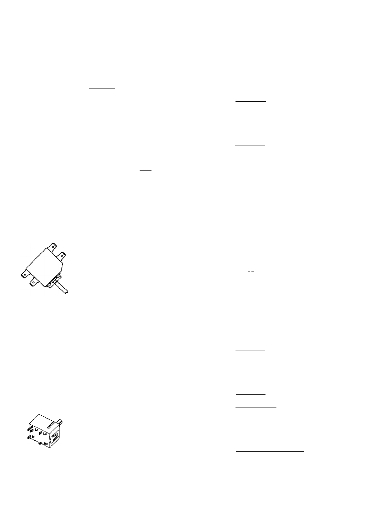
Rocker switch
Coil surface elements
6" and 8"
block
Ribbon radiant
elements
Ribbon surface
thermal limiter/hot
light switch
Bake element
Test continuity of receptacle
terminals.
Remove one lead from switch
terminal and measure resistance
across terminals.
Measure voltage at indicator light.
Measure continuity of switch
positions;
Closed
Open
Test continuity of terminals. Continuity, if not replace.
Remove element and turn surface
element on and test for voltage at
terminal block.
Remove one wire lead from element
and measure resistance of the
element.
Turn surface element on and test for
voltage. See wiring diagram and
schematic.
1a-2a 240 VAC
1b-2b 120 VAC
Disconnect leads and measure
resistance on the foNoviring:
1a-2a room temperature-continuity
1b-2b room temperature-infinite
Disconnect wire ieads to element and
measure resistance of terminals.
_______________
Indicates continuity with bulb screwed in.
If not replace.
Switch closed; 0 il
Switch open; Infinite resistance
If voltage is present and light does not
operate. Replace light.
If no voltage is present at indicator light
check wiring.
Ccmtinuity, if not replace.
Infinite, if not replace.
240 VAC
Continuity, if not replace.
1200W: 45 to 51 n
1500W: 36 to 41 Cl
Results
______________
_________________________
_________________________
2000W: 27 to 31 Q
2500W: 21 to 25 n
240 VAC
EtotirovM
q.n
TTl
uwbA
V‘
■u a
Continuity, approximately 23 Q,
if not replace.
Th«mwO>Oisc (TOO)
n n
Might
to la
r Î
trxr
061732
314907
31891202
RT2320003 Rev. 9
Broil element
Oven temperature
sensor
Infinite switch
Measure voltage at bake element.
Disconnect wire leads to element and
measure resistance of terminals.
Measure voltage at broil element.
Measure resistance.
Remove wiring from terminals HI and
H2. Connect Volt ohms meter to
HI and H2.
Measure the following for voltages at
LO, MED, HI;
HI to H2
240 VAC, see wiring diagram for terminal
identification.
If no voltage is present at bake element
check wiring.
Continuity, approximately 19 il,
if not replace.
240 VAC, see wiring diagram for terminal
identification.
If no voltage is present at broil element
check wiring.
Approximately 1100 o at room
temperature 75° F.
LO 5%
MED (4-5) 50%
HI 100%
240 VAC, if not replace switch.
__________________________
____________
Time On
Time Off
95%
50%
0%
April 1999
Page 3
Component Testing Information
A WARNING
To avoid risk of electrical shock, personal injury, or death, disconnect power to oven before servicing, unless testing requires it.
Illustratiort
053584
31715201— LH
31715202— RH
Opening
065780
305797
Component
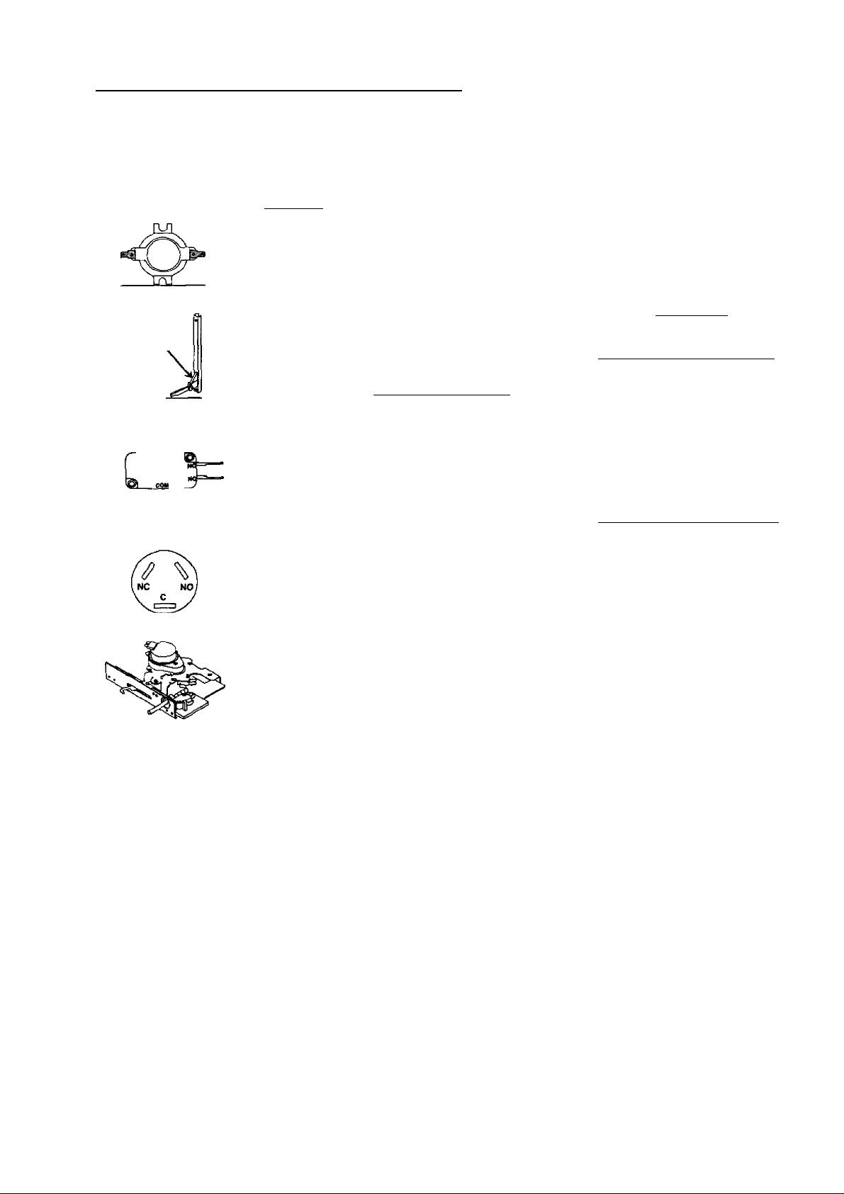
Control limit
Hinge Carefully open the hinge fully, and
Door lock switch
Door plunger switch Remove switch from unit and measure
Normally Closed
Verify proper operation.
Closed 245°F
Open 275“F
insert a wooden dowel or screwdriver
bit into opening.
Remove top and bottom screws
securing hinge.
Slide hinge top towards rear of unit
and guide hinge out through frame
opening or storage drawer.
Switch connection in following
positions:
Unlocked
Locked
Set ERC to Clean
the following points:
C-NC
C NO
Test Procedure Results
Continuity
Infinite
If open at room temperature, replace.
A CAUTION
Do not place hands in hinge area when
oven door is removed. Hinge can snap
closed and pinch hands or fingers.
COM-NO=Open, COM-NC=Closed
COM-NO=Closed, COM-NC=Open
Lock LED should flash
Lock LED and Oven LEO should
illuminate, If Lock LED does not
illuminate, check switch and wiring.
Plunger in infinite. Plunger out continuity.
Plunger in continuity, Plunger out infinite.
31797301
Autolatch assembly
with door plunger
switch
Disconnect wires and test for
continuity per diagram.
NC NC
LI L2 COMI PM com! no
X ■ I' Jr >L i
120 VAC LedVUntocfc
Motor
Door
Switch
April 1999
RT2320003 Rev. 9
Page 4

Component Testing Procedures
WARNING
To avoid risk of electrical shock, personal injury, or death, disconnect power to oven before servicing, unless
testing requires it.
____________
_______________________
____________________________________________
Illustration
Blr30D.-jH
ээшшвввв
ERC3 Controlled Oven temperature
ERC3 Controlled
ERC3 Controlled
ERC3 Controlled
Component
ERC3 - Touchmatic
electronic range
control
adjustment
Twelve hour off Control will automatically cancel any
Child lock out Control input features will be disabled
Drive requirements
Based on a 60
second cycle.
Test Procedure
FI—Shorted pad button.
F2—Oven cavity over temperature.
F3—Open circuit in oven temperature
sensor circuit.
F4—Shorted circuit in oven
temperature circuit.
F^-Defective watchdog circuit in
control.
F7—Failure of door lock switch sensing
with door locked.
F9—Failure of door lock switching
sensing with door unlocked.
DOOR—Lock status is not sensed
within 20 seconds of energizing door
lock relay.
Push BAKE pad.
Push SLEW pad until an oven
temperature greater than 500“F
displays.
Immediately push and hold BAKE pad
until "00” displays, approximately 5
seconds.
To decrease oven temperature (for a
cooler oven). Push SLEW pad until
negative numbers appear. Oven can be
adjusted from -05" to -35° lower. To
avoid over adjusting oven move
temperature -5° each time.
To increase oven temperature (for a
warmer oven), Push SLEW pad until
positive numbers appear. Oven can be
adjusted from 5* to 35° higher. To avoid
over adjusting oven move temperature
5° each time.
Push OVEN CANCEL button.
Temperature adjustment will be
retained even through a power failure.
cooking operation and remove all relay
drives 12 hours after the last pad touch.
and display will indicate “OFP, when
BAKE and CLOCK are pushed
simultaneously and held for 5 seconds.
Control wiItVetum to normal operation
by repeating the procedure.
Bake
Broil
Clean
Stage 1
Stage 2
Lock light
____________
Results
Verify actuator operation.
Check sensor wiring, sensor, and
temperature limiter.
Check sensor resistance and wiring.
Check sensor resistance and wiring.
Replace ERC3.
Check latch switch and door motor.
Check latch switch and door motor.
Verify operation of door latch switches.
While increasing or decreasing oven
temperature, this does not affect self
cleaning temperature.
100% bake
0% bake 100% broil
0% bake
0% bake
0% bake
0% bake
0% bake
Time controlled 15 minutes 0% bake
100% broil.
Time controlled 100% bake 10% broil.
On at the start of the clean cycle.
Off at approximately 400°F ± 25°F.
10% broil
93% broil 5
87% broil 4
80% broil
73% broil 2
67% broil 1
HI
3
RT2320003 Rev. 9
April 1999
Page 5

Wiring Diagram and Schematic
A WARNING
To avoid risk of electrical shock, personal injury, or death, disconnect power to oven before servicing, unless testing requires it.
A
April 1999
COLOR
color
RED
orange OR
YELLOW
GREEN
BLUE
VIOLET
BLACK BK
8R0* N
GRAY
HUE
NO TES :
.AU INT[*NAl » lfi[S AB£ laCA. liO 'C XL UIILESS 01HESKISE «0U D
? All RE PLACE Wm » IBES UUSl HAVE SAKE BATING AS
ORIGINAMI) IRES. •
J. SEE SERIAL PLATE FOR INPUT VOLTAGE/* ATIAOE rating.
4. DiNOFES optional EOUIPNEHT AND RELATE 0 * IRINC N01
supplied on sone uooees.
b.ELENENT WATlAGESVASr Bi MODEL. BEPLACENENl ELENEH15
RUST HAVE SAMI iATTACE AS ORIGINAL ELEMENTS,
6. FOR RANGE INST AELAT ION, USE COPPER * IRE ONLY.
i.CROUNDSIRAPNOTUSED for four* IRE INSTALLATIONS.
\kl ADMlKir -ELECIRICAl SHOCK HAZARD
W A KIN IN b -disconnect POWER Al MAIN
FUSE OR CIRCUIT BREAKER BEFORE SERVICING
FAILURE TO DO SO COULD RESULT IN SERIOUS
INJURY OR DEATH.
lOULEUa
SYMBOL
RD ROUGE
ORANGE
YL JAUNE
GN
BU DIEU
VT
MARRON
OR
CY GRIS
H H BLANC
VERT
VIOLET
HOIR
DI AGR AM
DANGER -DEBRANCHER L’ALIMENTATION ELECTRIQUE.
LE MANQUE DE RESPECT DE CETTE CONSIGNE POUR RA IT
AVOIR COMME RESULTAT UNE BLESSURE GRAVE OU MORTELLE.
ARR6400
-RISQUE DE CHOC ELECTRIQUE
AVANT D'ENTRETENIR CETTE UNITE.
RT2320003 Rev. 9
Page 6

Wiring Diagram and Schematic
A WARNING
To avoid risk of electrical shock, personal injury, or death, disconnect power to oven before servicing, unless
testing requires it. ____________________________________________________
RT2320003 Rev. 9
ARR6400
6
April 1999
Page 7

Wiring Diagram and Schematic
A WARNING
To avoid risk of electrical shock, personal injury, or death, disconnect power to oven before servicing, unless testing requires it.
April 1999
COLOR
COLOR
RED
ORANGE OR
YELLOW
GREEN
blue
VIOLET
BLACK
BROWN BR
GRAY
[white
NO TEWHS :
ALL INTERNAL WIRES ARE 1BGA . I50tC XL UNLESS
OTHERWISE NOTED. SF2 IS SEW-2/SF3 200tC .
ALL REPLACEMENT WIRES UUST HAVE SAME RATING AS
original wires -
SEE SERIAL PLATE FOR INPUT VOLTACE/WATTAGE RATING
*OR (-------------)DENOTES OPTIONAL EOlflPMENT A
SUPPLIED ON SOME MODELS.
ELEMENT WATTAGES VARY BY MODEL. REPLACEMENT ELEMENTS
MUST HAVE SAME WATTAGE AS ORIGINAL ELEMENTS.
FOR RANGE INSTALLATION. USE COPPER WIRE ONLY.
CftOUNO STRAP NOT USED FOR FOUR WIRE INSTALLATIONS
WARN ING
A
COULEUR
SYMBOL
RD ROUGE
ORANGE
YL JAUNE
VERT
GN
BLEU
BU
VIOLET
VT
BK NOIR
MARRON
GRIS
GY
[ BLANC P
ANO RELATED WIRING NOT BLOCK
- electrical shock hazard
FUSE OR Ciftcun breaker BEFORE SERVICING.
failure to 00 SO COULO RESULT IN SERIOUS
INJURY OR DEATH.
- DISCONNECT POWER AT MAIN
MAIN ^
TERMINAL
* POWER CORÇ
DIAGRAM
„ ^ - RISQUE DE CHOC ELECTRIQUE
DANGFR- DEBRANCHER L'ALIMENTATION ELECTRIQUE
LE MANQUE DE RESPECT DE CETTE CONSIGNE POURRAIT
AVOIR COMME RESULTAT UNE BLESSURE GRAVE OU MORTELLE.
ART6510
AVANT D'ENTRETENIR CETTE UNITE.
CHASSIS
GND
RT2320003 Rev. 9
Page 8

Wiring Diagram and Schematic
;
__________________
To avoid risk of electrical shock, personal injury, or death, disconnect power to oven before servicing, unless
testing requires it.
A WARNING
___________________
RT2320003 Rev, 9
ART6510
8
April 1999
 Loading...