

Page 1
PBWS01A
®
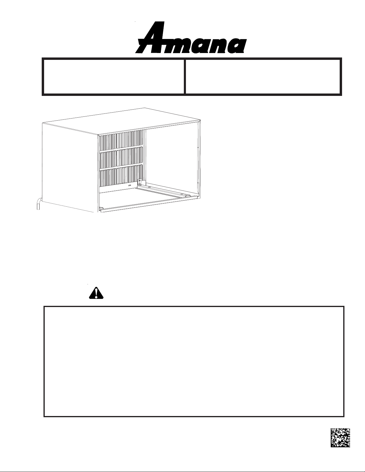
Wall Sleeve
Installation Instructions
General Information
The wall sleeve must be installed before the air
conditioner chassis can be set in place. Read the
instructions thoroughly before proceeding.
Table of Contents
General Information ................................................................. 1
Preinstallation Considerations................................................ 2
Wall Sleeve Inst allation............................................................ 3
Condensate Drain Kit............................................................... 3
RECOGNIZE THIS SYMBOL AS A SAFETY PRECAUTION.
ATTENTION INSTALLING PERSONNEL
As a professional installer you have an obligation
to know the product better than the customer. This
includes all safety precautions and related items.
Prior to actual installation, thoroughly familiarize
yourself with this Instruction Manual. Pay special
attention to all safety warnings. Often during
installation or repair, it is possible to place yourself
in a position which is more hazardous than when
the unit is in operation.
Remember, it is your responsibility to install the
product safely and to know it well enough to be
able to instruct a customer in its safe use.
Safety is a matter of common sense...a matter of
thinking before acting. Most dealers have a list of
specific good safety practices...follow them.
The precautions listed in this Installation Manual
are intended as supplemental to existing practices.
However, if there is a direct conflict between existing
practices and the content of this manual, the
precautions listed here take precedence.
IO-657A
Amana® is a registered trademark of Maytag Corporation or its related
companies and is used under license to Goodman Company, L.P., Houston, TX.
All rights reserved.
March 2009
Page 2
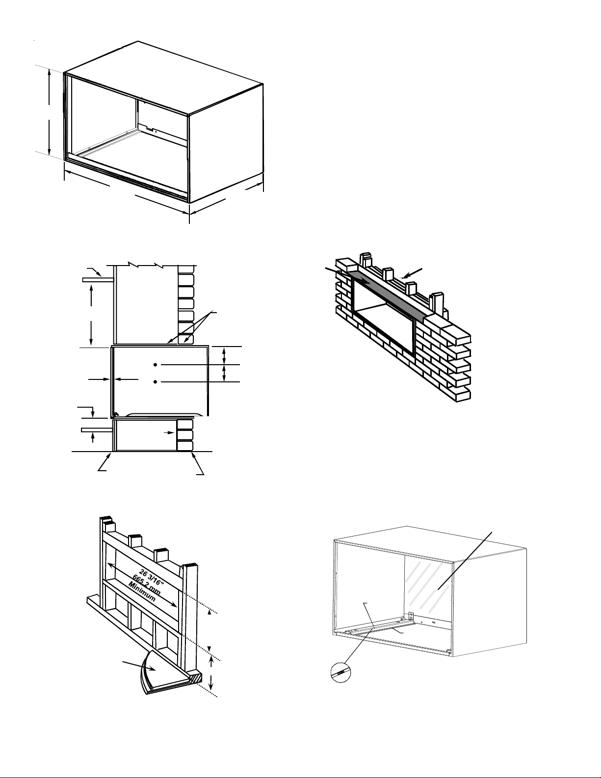
15 3/4"
401 mm
26"
661 mm
Figure 1
Wall Sleeve Dimensions
16 3/4"
426 mm
Preinstallation Considerations
Before proceeding with the sleeve installation, ensure the
following guidelines for locating the wall opening and
sleeve are met:
• The wall opening must be the correct size. See Figure
1 for wall sleeve dimensions and Figure 3 for minimum
wall opening size.
• The wall sleeve must be installed with a 5” minimum
clearance to the floor and 1 1/2” to adjacent walls. See
Figure 2 for minimum projections of the sleeve into
and out of the room.
• If installed in a concrete or masonry wall, a lintel must
be provided in the wall opening for support. Do not
use the wall sleeve as a lintel. If the wall is less than
8” thick or of hollow construction, an alternate means
of support for the sleeve must be provided. See Figure
4 for a typical lintel construction.
Ceiling
24"
Min.
1" Min.
5" Min.
Inside Wall
Outside Wall
Figure 2
Minimum Unit Clearances
Lintels
6"
6"
1" Min.
Lintel
Wood
Frame
Figure 4
Framing with Lintel
• When installed in the opening, the wall sleeve must be
level from side to side and sloped one quarter bubble
front to back. DO NOT SLOPE THE WALL SLEEVE
TOWARD THE ROOM. See Figure 5.
Flashing
Waterproof Barrier
"
m
m
6
1
u
m
/
3
m
6
i
.
1
n
1
i
5
0
1
M
4
Finished Floor
5"
Figure 3
Minimum Wall Opening Dimensions
Level
Rail
1/4 Bubble Lower
Front to Back
Figure 5
Sleeve Installation
2
Page 3

Waterproof barrier should remain in place until the unit is
installed. An accessory metal front panel, PBWMFC, is
also available, but must be purchased separately.
• Attach the sleeve using four #12x2” wood screws (for
wood constructed buildings) or four #12x2” masonry
screws (for cement or brick constructed buildings)
(Figure 6). Make sure the wall construction is adequate to support the unit.
Alternative
Fastening Method
(Field Supplied)
Wood Screw
Mounting
Holes
(Drilled by
Installer)
Plastic
Anchor
Toggle Bolt
Screws
Expansion
Anchor Bolt
Figure 6
Attaching Wall Sleeve to Opening
• Provide adequate sealing and insulation around the
sleeve after it is installed. See Figure 7 for one
example of construction.
Concrete
Lintel
14 3/4"
375 mm
Maximum
(No Accessories)
Wall Sleeve Installation
After the wall opening is checked and approved for strength,
location, size, and clearances, install the wall sleeve as
follows:
1. Remove the outside enclosure panel from the wall
sleeve.
2. Slide the wall sleeve into the wall opening. Do not
distort the cabinet shape to fit the wall opening; the unit
chassis must fit snugly and uniformly into the wall
sleeve.
3. Locate the sleeve within the range of minimum projections, as shown in Figure 2, so both sides are at least
the minimum projection from the wall.
4. Check the level of the wall sleeve. For proper drainage, the sleeve should be level from side to side and
one-quarter bubble front to back (outside).
5. Drill two holes in both sides of the wall sleeve so
mounting screws can be secured to wall supports.
See Figure 6 for location of screw holes. DO NOT
DRILL THROUGH BOTTOM OF SLEEVE.
6. Check the level of the wall sleeve and adjust if necessary.
7. Caulk or seal around the outside of the entire sleeve.
8. If the unit chassis is not to be installed immediately,
replace the enclosure panel on the outside opening of
the sleeve to limit weather damage to the building
interior.
9. Recycle or dispose of packaging materials according
to local codes.
"
4
/
3
6
1
m
m
Finished
Floor
6
2
4
Steel
Lintel
Power Supply
Conduit
Figure 7
Block and Brick Veneer Installation
• Do not use extension cords with the unit.
Caulk Top,
Bottom, and
Both Sides
Condensate Drain Kit
An outdoor condensate drain kit (Figure 8) is available on
all models. An accessory drain kit, DK900D, is available
for internal drain applications and must be purchased
separately. The drain kit must be installed before installing
the wall sleeve in the wall. See the drain kit for actual
installation instructions.
Kit Ordering
Number
DK900D Internal Conde nsate Drain Kit
Description
Figure 8
Condensate Drain Kit
3
Page 4

©2006, 2009 Goodman Company, L.P.
Fayetteville, TN 37334
www.amana-hac.com
4
 Loading...