

Page 1
THROUGH THE W ALL
ROOM AIR CONDITIONER
WITH OPTIONAL ELECTRIC HEAT
INSTALLATION INSTRUCTIONS
RECOGNIZE THIS SYMBOL AS A SAFETY PRECAUTION.
ATTENTION INSTALLING PERSONNEL
As a professional installer you have an obligation to know the product better than the customer. This includes all
safety precautions and related items.
Prior to actual installation, thoroughly familiarize yourself with this Instruction Manual. Pay special attention to all
safety warnings. Often during installation or repair it is possible to place yourself in a position which is more
hazardous than when the unit is in operation.
Remember, it is your responsibility to install the product safely and to know it well enough to be able to instruct a
customer in its safe use.
Safety is a matter of common sense...a matter of thinking before acting. Most dealers have a list of specific good
safety practices...follow them.
The precautions listed in this Installation Manual are intended as supplemental to existing practices. However, if
there is a direct conflict between existing practices and the content of this manual, the precautions listed here take
precedence.
is a registered trademark of Maytag Corporation or its related companies and is used under
license to Goodman Company, L.P., Houston, TX. All rights reserved.
IO-370A
May 2010
www.amana-ptac.com
© 2010 Goodman Company, L.P.
Page 2
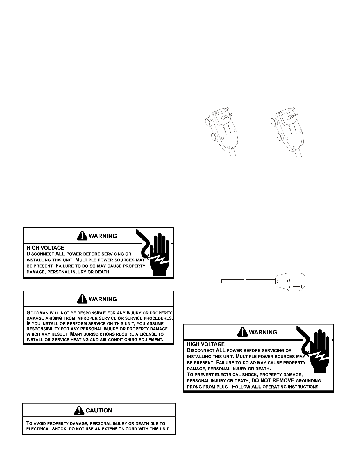
TABLE OF CONTENTS
UNIT FEATURES
Important Note to Owner ............................................................. 2
Important Note to Servicer........................................................... 2
Operating Instructions ................................................................. 2
Unit Features ................................................................................ 2
Installation Instructions ............................................................... 3
Wiring........................................................................................... 6
Air Conditioner Features ............................................................. 7
Additional Information ................................................................11
Normal Operating Sounds and Conditions ...............................11
Obtaining Service ....................................................................... 11
Consumer Warranty .................................................................. 12
Commercial Warranty ............................................................... 13
IMPORTANT NOTE TO THE HOMEOWNER
This manual is to be used by qualified, professionally trained HVAC
technicians only. Goodman does not assume any responsibility
for property damage or personal injury for improper service procedures or services performed by an unqualified person.
IMPORTANT NOTE TO THE SERVICER
Read this manual and familiarize yourself with the specific items
which must be adhered to before attempting to service this unit.
The precautions listed in this Installation Manual are intended as
supplemental to existing practices. However, if there is a direct
conflict between existing practices and the content of this manual,
the precautions listed here take precedence.
This unit has many features which are different than those found
on conventional units. The servicer must be familiar with these
features in order to properly service the unit.
Check the data specification plate and ensure the proper voltage
and current rating is available for the type power plug on the unit.
DO NOT REMOVE THE GROUNDING PRONG FROM THE POWER
CORD. Note the types of acceptable plugs in Figure 1.
Refer to the data serial plate for electrical requirements.
120V
15 Amp
230V
20 Amp
Figure 1
• LCDI or AFCI Power Cords - Underwriters Laboratories and
the National Electric Code (NEC) now require power cords
that sense current leakage and can open the electrical circuit to the unit on units rated at 250 volts or less. In the event
that unit does not operate, check the reset button located on
or near the head of the power cord as part of the normal
troubleshooting procedure.
OPERATING INSTRUCTIONS
Check the data specification plate and ensure the proper voltage
and current rating is available for the type power plug on the unit.
DO NOT REMOVE THE GROUNDING PRONG FROM THE POWER
CORD. Note the types of acceptable plugs on the following figure.
Refer to the data serial plate for electrical requirements.
LCDI Power Cord
Figure 2
VOLTAGE MEASUREMENTS
Before connecting the unit, measure the supply voltage. Voltage
must fall within the voltage utilization range given in the following
table.
2
Page 3
Operating Voltage
CHASSIS INST ALLATION
Unit Voltage
Voltage Utili zat ion Range
Rating Min imum Maximum
230/280 187 253
115 103 126
INSTALLATION INSTRUCTIONS
To ensure that the unit operates safely and efficiently, it must be
installed, operated, and maintained according to these installation and operating instructions and all local codes and ordinances,
or, in their absence, with the latest edition of the National Electrical
Code. The proper installation of this unit is described in the following sections. Following the steps in the order presented should
ensure proper installation.
SLEEVE INST ALLA TION
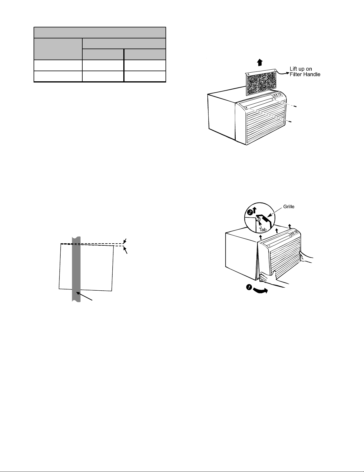
In order for condensate water to drain properly inside the unit, the
sleeve must be installed properly:
• Level from right to left.
• A slight downward pitch from the indoor side to the outdoor
side as shown in Figure 3.
Refer to the Installation Instructions supplied with the wall sleeve
for a complete description of the installation procedure.
NOTE: Wall sleeve (PBWS01A ) is not shipped with chassis and
must be purchased separately.
OutsideInside
Level
1. Remove front grille. See Figure A.
Figure A
The front grille can be removed for more thorough cleaning or to
make the model and serial numbers accessible. To remove, pull
the filter out and remove the two grille screws.
Wall
Sleeve
1/4 Bubble
Tilt To
Outside
Outside
Wall
Figure 2
REAR LOUVER PANEL
A TWKG rear louver panel kit is required for unit installation into an
existing Amana® brand 26” wall sleeve. A TWEAK or TWF AK adapter
kit is required for unit installation into an existing 27” wall sleeve.
The rear louver panel directs air flow for proper unit operation and
protects the outdoor coil. The panel must be installed before installing the chassis. These kits are not supplied with the unit.
Refer to the Installation Instructions supplied with the rear louver
panel kit for a complete description of the installation procedure.
Pull the grille out from the bottom and lift up from the tabs on the
top of the case.
2. Remove the grounding screw and wire next to the grounding
symbol on right side of chassis control panel (Figure 3). Attach other end of ground wire to the hole in the bottom right
side of the sleeve with #8 x 3/8” blunt point sheet metal screw .
The hole on the sleeve is indicated by grounding symbol on
the sleeve. Slide chassis part of the way into the sleeve and
reattach the ground wire back to the hole on the right side on
the control panel area next to the grounding symbol.
3
Page 4
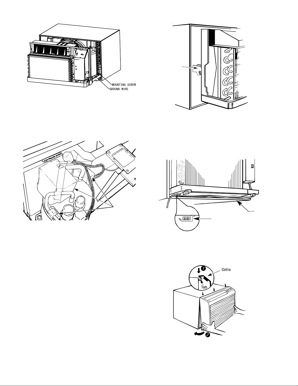
Figure 3
Locking
Plate
3. Remove shipping pads inside air conditioner next to
compressor. (See Figure B.)
Remove
shipping
pads
Figure B
4. Carefully slide the chassis into the sleeve. Ensure that
the ground wire is not pinched or in the path of the
condenser fan.
5. Loosen locking plate screw and rotate tab with tab
behind wall case flange (See Figure C) then tighten
locking plate screw.
Figure C
6. If outlet is on the left side of the unit, route power cord as
shown in Figure D.
Power
Clamp
Cord
Figure D
To replace front grille:
Hook the tabs on the front grille even with the tabs on the case and
snap into place. Replace the screws and filter. Refer to Page 3,
Figure A.
4
Page 5

VENT CONTROL AND AIR DIRECTION (See Figure E)
The vent control is located behind the front grille on the right side
of the air discharge area. When set at CLOSE only the air inside
the room will be circulated and conditioned. When set at OPEN,
some inside air is exhausted outside.
AIR DIRECTION:
Horizontal louvers on the front grille let you control the air direction
up and down.
Locating
Hole
Screw Hole
OPEN posi t io n
(Mesh end toward back)
Screw Hole
CLOSE position
(Mesh end toward front)
Locating
Hole
Figure E
To open or close the vent:
1. Remove the front grille.
2. Remove the vent card screw.
3. Remove the vent card, turn it over and replace it by locating
rear hole in card over locating pin inside air discharge and
reattaching screw at front.
Screw
Remove the front grille to adjust the vertical louvers side-to-side
to direct the air left or right.
Figure 4
Figure 5
IMPORTANT NOTES:
1. The unit is equipped with a rubber-grommet-mounted
compressor. These grommets are factory set and require
no adjustment.
2. Obstruction to air flow must be checked and removed.
Check the indoor and outdoor grilles for obstructions. The
unit must be located where curtains, furniture, trees, or
other objects do not block air flow to and from the unit. If air
is obstructed and/or deflected back into the unit, the air
conditioner’s compressor may cycle on and off rapidly.
This could cause damage to the compressor.
5
Page 6

WIRING
Before wiring the unit, please review the following warnings and
cautions.
6
Page 7

AIR CONDITIONER FEATURES
ELECTRONIC CONTROL OPERA TING INSTRUCTIONS
Before you begin, thoroughly familiarize yourself with all of the functions of the control panel and remote as shown below and follow the
instructions. The unit can be controlled by the touchpad alone or with the remote control.
COOLING ONL Y
UNIT
HEA T/COOL UNIT
SETS FA N
SPEED
SETS FAN
SPEED
SETS MODE
AUTO
HIGH
MED
LOW
FAN
SPEED
SLEEP
SLEEP MODE
SETS MODE
AUTO
HIGH
MED
LOW
FAN
SPEED
SLEEP
RAISES
TEMPERATURE
OR TIME
COOL
ENERGY
SAVER
FAN
ONLY
MODE
TIMER
TIMER
RAISES
TEMPERATURE
OR TIME
HEAT
COOL
ENERGY
SAVER
FAN
ONLY
MODE
TIMER
DISPLAYS
TEMPERATURE
+
TEMPERATURE/TIMER
POWER
DISPLAYS
TEMPERATURE
+
TEMPERATURE/TIM ER
POWER
-
Set
-
Set
LOWERS
TEMPERATURE
OR TIME
TURNS UNIT
ON OR OFF
LOWERS
TEMPERATURE
OR TIME
TURNS UNIT
ON OR OFF
SLEEP MODE
ACTIVATES
TIMER
LOWERS
TIME
Select Mode
SETS FAN
SPEED
LOWERS
TEMPERATURE
TURNS UNIT
ON OR OFF
NOTE:
The remote control will work normally after a 5 second reset.
TIMER
_
M
O
D
E
Fan
_
REMOTE CONTROL
TIMER
SLEEP
∧
∨
ON/OFF
+
Fan
AUTO
+
RAISES
TIME
SLEEP
Mode
AUTO
Mode
SETS FAN
SPEED
RAISES
TEMPERATURE
BATTER Y SIZE: AAA
7
Page 8

A
AIR CONDITIONER FEATURES
TO TURN UNIT ON:
AUTO
HIGH
MED
LOW
FAN
SPEED
SLEEP
HEAT
COOL
ENERGY
SAVER
FAN
ONLY
MODE
TIMER
+
TEMPERATURE/TIMER
POWER
Set
-
PRESS
ON/OFF
BUTTON
TO CHANGE TEMPERATURE SETTING:
AUTO
HIGH
MED
LOW
FAN
SPEED
SLEEP
HEAT
COOL
ENERGY
SAVER
FAN
ONLY
MODE
TIMER
+
TEMPERATURE/TIMER
POWER
Set
-
PRESS TO RAISE
PRESS TO LOWER
SPEED
SLEEP
SPEED
SLEEP
YOU WILL SEE:
HEAT
COOL
ENERGY
SAVER
FAN
ONLY
MODE
TIMER
FAN
AUTO
HIGH
MED
LOW
YOU WILL SEE:
HEAT
COOL
ENERGY
SAVER
FAN
ONLY
MODE
TIMER
FAN
HIGH
MED
LOW
UTO
72
+
TEMPERATURE/TIMER
POWER
72
+
TEMPERATURE/TIMER
POWER
Set
-
Set
-
NOTE:
Tap or hold either up ( S ) or down ( T ) button until the desired temperature is seen on the display. This temperature will be
automatically maintained anywhere between 60°F (16°C) and 86°F (30°C) for both cooling and heating modes.
If you want the display to read the actual room temperature, select the FAN ONLY MODE.
TO CHANGE FAN SPEEDS:
AUTO
HIGH
MED
LOW
FAN
SPEED
SLEEP
HEAT
COOL
ENERGY
SAVER
FAN
MODE
TIMER
Set
-
+
TEMPERATURE/TIMER
POWER
TO CHANGE AUTO FEATURE:
AUTO
HIGH
MED
LOW
FAN
SPEED
SLEEP
HEAT
COOL
ENERGY
SAVER
FAN
MODE
TIMER
Set
-
+
TEMPERATURE/TIMER
POWER
PRESS FAN SPEED
BUTTON
SELECT SPEED
PRESS FAN SPEED
BUTTON
SELECT AUTO FAN
LIGHT ON
LIGHT ON
YOU WILL SEE
THE SPEED CHOSEN:
AUTO
HIGH
MED
LOW
FAN
SPEED
SLEEP
HEAT
COOL
ENERGY
SAVER
FAN
ONLY
MODE
TIMER
+
TEMPERATURE/TIMER
YOU WILL SEE:
AUTO
HIGH
MED
LOW
FAN
SPEED
SLEEP
HEAT
COOL
ENERGY
SAVER
FAN
ONLY
MODE
TIMER
+
TEMPERATURE/TIMER
72
POWER
72
POWER
Set
-
Set
-
NOTE:
The fan speed will automatically set to the speed needed to provide optimum comfort setting with the set temperature. If the room needs
more cooling, the fan speed will automatically increase. If the room needs less cooling, the fan speed will automatically decrease. Auto
fan speed cannot be used when in the FAN ONLY mode.
8
Page 9

AIR CONDITIONER FEATURES
TO OPERATE ON FAN ONLY:
YOU WILL SEE:
LIGHT ON
AUTO
HIGH
MED
LOW
FAN
SPEED
SLEEP
HEAT
COOL
ENERGY
SAVER
FAN
ONLY
MODE
TIMER
+
TEMPERATURE/TIMER
POWER
Set
PRESS
MODE
-
BUTTON
CHOOSE
FAN ONLY
AUTO
HIGH
MED
LOW
FAN
SPEED
SLEEP
Note: Use this function only when cooling is not desired, such as for room air circulation. You can choose any fan speed you prefer,
except AUTO FAN. During this function, the display will show the actual current temperature, not the set temperature as in the cooling
mode.
TO USE THE ENERGY SAVER FEATURE:
HEAT
COOL
ENERGY
SAVER
FAN
ONLY
MODE
TIMER
+
TEMPERATURE/TIMER
YOU WILL SEE:
72
POWER
Set
-
LIGHT ON
AUTO
HIGH
MED
LOW
FAN
SPEED
SLEEP
HEAT
COOL
ENERGY
SAVER
FAN
ONLY
MODE
TIMER
+
TEMPERATURE/TIMER
POWER
Set
-
MODE
BUTTON
CHOOSE
ENERGY SAVER
PRESS
AUTO
HIGH
MED
LOW
FAN
SPEED
SLEEP
HEAT
COOL
ENERGY
SAVER
FAN
ONLY
MODE
TIMER
72
+
TEMPERATURE/TIMER
POWER
Set
-
Note: In this mode, the fan will continue to run for 1 (one) minute after the compressor or electric heat strip shuts off. This results in
wider variations of room temperature and is normally used when the room is unoccupied.
YOU WILL SEE
TIMER-DELAY START/STOP FEATURE:
AUTO
HIGH
MED
LOW
FAN
SPEED
SLEEP
HEAT
COOL
ENERGY
SAVER
FAN
MODE
TIMER
+
TEMPERATURE/TIMER
POWER
Set
-
TIMER BUTTON
THEN PRESS
TEMP/TIMER
PRESS
AUTO
HIGH
MED
LOW
FAN
SPEED
SLEEP
THE TIME CHOSEN:
HEAT
COOL
ENERGY
SAVER
FAN
ONLY
MODE
TIMER
0.5
+
TEMPERATURE/TIMER
POWER
Set
-
BUTTON
NOTES:
1. For DELAY STOP, the unit must be in the ON position.
2. For DELAY ST ART, the unit must be in the OFF position.
T o adjust the timer setting, tap or hold the UP ( S ) arrow or DOWN
( T ) arrow to change the delay time by 1/2 hour (0.5) increments
up to 10 hours; then 1 hour increments up to 24 hours. The
control will count down the time remaining until start or stop (8,
7.5, 7, etc.).
After setting the Timer, the unit will enter into Timer mode within
5 seconds. The Timer light will then be on and the Set light will
be off.
While in Timer mode, the Set temperature and fan speed will
maintain previously set temperature and fan speed and the Temperature display will show the set temperature. (There will be no
display if the power is turned off.) By pressing the Timer once,
the LED displays the remaining portion of the set time. (The LED
will return to set temperature within 5 seconds.) When in Fan
Only mode, the LED will only display the room temperature; it will
not display set temperature.
Turning the unit “ON” or “OFF” at any time will cancel the DELAY
START/STOP function. The DELA Y ST ART/STOP feature will work
until the unit starts or stops. Once this has happened, the above
steps must be repeated again.
NOTE: Factory default setting is for °F. To convert to °C, press the
INCREASE
approximately 5 seconds. To return to °F, repeat the procedure.
LIGHT ON
SS
S
/ DECREASE
SS
TT
T
buttons simultaneously for
TT
9
Page 10

AIR CONDITIONER FEATURES
F
F
HEA TING FEA TURE (on some models):
AUTO
HIGH
MED
LOW
FAN
SPEED
SLEEP
HEAT
COOL
ENERGY
SAVER
FAN
ONLY
MODE
TIMER
+
TEMPERATURE/TIMER
POWER
Set
-
SELECT HEAT
PRESS
MODE
BUTTON
YOU WILL SEE:
AUTO
HIGH
MED
LOW
FAN
SPEED
SLEEP
HEAT
COOL
ENERGY
SAVER
FAN
ONLY
MODE
TIMER
72
+
TEMPERATURE/TIMER
POWER
Set
-
Note: This feature can be used with any combination of FAN Speeds, Timer or Sleep Modes. When in the “heat” Mode, the fan will run
continuously while heat is needed. The temperature will automatically be maintained anywhere between 61°F (16°C) and 86°F (30°C).
SLEEP FEA TURE:
AUTO
HIGH
MED
LOW
FAN
SPEED
SLEEP
HEAT
COOL
ENERGY
SAVER
FAN
ONLY
MODE
TIMER
+
TEMPERATURE/TIMER
POWER
Set
-
PRESS
MODE
BUTTON
SELECT
YOU WILL SEE:
AUTO
HIGH
MED
LOW
FAN
SPEED
SLEEP
HEAT
COOL
ENERGY
SAVER
FAN
ONLY
MODE
TIMER
Set
-
+
TEMPERATURE/TIMER
POWER
SLEEP
Note: After pressing this button, SLEEP ON and SLEEP OFF can be selected. After powered on, SLEEP OFF is defaulted. After the unit
is turned off, the SLEEP function is cancelled. If SLEEP mode is set while the unit is in COOL or ENERGY SA VER modes, the SET TEMP.
would increase 1.8°F (1°C) in 1 hour and 3.6°F (2°C) in 2 hours. If SLEEP mode is set while unit is in HEA T mode, the SET TEMP. would
decrease 1.8°F (1°C) in 1 hour and 3.6°F (2°C) in 2 hours. When unit is in FAN ONLY and AUTO modes, this function is not available.
TO TURN UNIT OFF:
AUTO
HIGH
MED
LOW
FAN
SPEED
SLEEP
ENERGY
ONLY
MODE
TIMER
HEAT
COOL
SAVER
FAN
FAULT CODES
AUTO
HIGH
MED
LOW
FAN
SPEED
SLEEP
If the display reads “F1”, a sensor has failed.
AUTO
HIGH
MED
LOW
FAN
SPEED
SLEEP
+
TEMPERATURE/TIMER
POWER
HEAT
COOL
ENERGY
SAVER
FAN
ONLY
MODE
TIMER
HEAT
COOL
ENERGY
SAVER
FAN
ONLY
MODE
TIMER
Set
-
F1
+
TEMPERATURE/TIMER
POWER
F4
+
TEMPERATURE/TIMER
POWER
PRESS
ON/OFF
BUTTON
Set
-
Set
-
YOU WILL SEE:
AUTO
HIGH
MED
LOW
FAN
SPEED
SLEEP
AUTO
HIGH
MED
LOW
FAN
SPEED
SLEEP
HEAT
ENERGY
SAVER
FAN
ONLY
MODE
TIMER
COOL
If the display reads “F2”, a sensor has failed.
AUTO
HIGH
MED
LOW
FAN
SPEED
SLEEP
HEAT
ENERGY
SAVER
ONLY
MODE
TIMER
COOL
FAN
HEAT
COOL
ENERGY
SAVER
FAN
ONLY
MODE
TIMER
2
+
TEMPERATURE/TIMER
POWER
J
+
TEMPERATURE/TIMER
POWER
Set
-
Set
-
Set
-
+
TEMPERATURE/TIMER
POWER
If the display reads “F4”, a sens or has failed.
If the disp lay reads “FJ”, a sensor has failed.
10
Page 11

ADDITIONAL INFORMATION
• The remote control will operate all the control panel features.
Instructions will be the same.
• The “COOL” circuit has an automatic 3 minute time de-
layed start if the unit is turned off and on quickly. This
prevents overheating of the compressor and possible circuit breaker tripping.
NOTE: The fan will continue to run during this time.
• The control will maintain any set temperature between 60°F
and 90°F (cooling), 55°F and 80°F (heating).
• The control is capable of displaying temperature in degrees
(Fahrenheit) or degrees (Celsius). To convert from one to the
other, press and hold the UP and DOWN Temperature Selection Pads at the same time for 3 seconds.
COMPRESSOR
The compressor is hermetically sealed, permanently lubricated
and requires no additional oiling.
FRONT PANEL AND GRILLE
The front panel and grille can be cleaned with a mild soap or
detergent. Do not use hydrocarbon-based cleaners (e.g. acetone,
benzene, naphtha, gasoline, etc.) to clean the front panel or grille.
Use care when cleaning the control area. Do not use an excessively wet cleaning cloth.
SCHEDULED MAINTENANCE
T o achieve continuing top performance and high efficiency , a regular
cleaning/inspection schedule must be established. Maintaining
this schedule can be accomplished by either a local maintenance
staff or an authorized servicer and must follow the instructions
described in this manual.
• If the unit is operated in a dusty climate, dust may collect in
the basepan and clog the condenser coil. It is advisable to
remove the unit from the sleeve and thoroughly clean the
basepan and condenser coil on a periodic basis.
• If the unit is installed ocean side or in a corrosive atmosphere,
its life may be greatly reduced by the corrosive environment.
Under these conditions, the unit should be removed from the
sleeve and completely cleaned once a year. At that time any
scratches or blisters on the painted surfaces should be
sanded and repainted.
OUTDOOR COIL CLEANING
The coils on the outdoor side of the air conditioner should be
checked regularly. For cleaning outside coil, remove the 6 screws
that mount the condenser coil top cover to condenser shroud.
NORMAL OPERATING SOUNDS
AND CONDITIONS
POPPING OR GURGLING SOUNDS
This sound is the refrigerant traveling through the lines. This is a
normal sound which may be heard for a few seconds after the unit
shuts off.
WA TER TRICKLING SOUNDS
This sound is produced by the water as it is picked up and run
over the coils. This procedure improves the efficiency of the unit
and helps with water removal.
WA TER DRIPPING
Water will collect in the basepan during high humidity days.
ST ARTING DELA Y
You may notice a short delay in the startup if you try to restart the
unit too soon after turning it off or if you adjust the thermostat right
after the compressor has shut off. This delay protects the compressor.
Obtaining Service
In the unlikely event this unit requires repair or servicing beyond
what is covered in this manual, contact an authorized service organization.
To obtain an authorized servicer, contact your sales representative or agency .
11
Page 12

WARRANTY LIMITATIONS:
WE ARE NOT RESPONSIBLE FOR:
• Damage or repairs required as a result of faulty installation or application
CONSUMERS
atmosphere or other conditions beyond our reasonable control
compatible with the unit
cleaning of the coils, filter cleaning and/or replacement, or damage caused by failure to
perform such maintenance
servicing
• Damage or repairs required as a result of floods, fires, wind, lightning, accidents, corrosive
• Damage or repairs required as a result of the use of components or accessories not
• Units installed outside of the United States and Canada
• Normal maintenance, as described in the installation and operating manual, such as
• Parts or accessories not supplied or designated for use by us
• Damage or repairs required as a result of any improper use, maintenance, operation or
• Damage or failure to start due to interrupted and/or inadequate electrical service
• Changes in the appearance of the unit that do not affect its performance
• Replacement of fuses and replacement or resetting of circuit breakers
THIS WARRANTY IS THE ONL Y EXPRESS WARRANTY PROVIDED ON THE UNITS COVERED;
AND ANY IMPLIED WARRANTIES, INCLUDING ANY IMPLIED WARRANTY OF MERCHANT-
ABILITY OR FITNESS FOR A PARTICULAR PURPOSE ARE LIMITED TO THE DURATION OF
THIS WARRANTY. Some states do not allow limitations on how long an implied warranty lasts,
so the above limitation may not apply to you.
WHETHER ANY CLAIM IS BASED ON NEGLIGENCE OR OTHER TORT, BREACH OF WAR-
RANTY OR OTHER BREACH OF CONTRACT , OR ANY OTHER THEORY, IN NO EVENT SHALL
WE BE LIABLE FOR INCIDENTAL OR CONSEQUENTIAL DAMAGES, INCLUDING BUT NOT
LIMITED TO LOST PROFITS, LOSS OF USE OF A UNIT OR OTHERWISE. Some states do not
allow the exclusion or limitation of incidental or consequential damages, so the above
exclusion may not apply to you.
This warranty gives you specific legal rights, and you may also have other rights which vary
from state to state.
nd
2010 Goodman Company , L.P .
©
Brand Servicer.
®
LIMITED WARRANTY
RAC WINDOW TYPE H & C (AE, AH, PBC, PBE, PBH)
years after the date of purchase, we will repair (to include labor) any refrig-
th
This warranty is extended only to purchasers for personal, family or household use. A
distinct warranty is extended to commercial customers.
Amana® brand RAC window-type heating or air conditioning units identified as AE, AH,
PBC, PBE and PBH units are warranted by Goodman Company, L.P. to consumers
against defects in materials and workmanship under normal use and maintenance, as
provided below.
FIRST-YEAR COVERAGE (ENTIRE UNIT): We will repair or replace, free of charge (to
include labor), any part of a unit that proves to be defective due to workmanship or
materials within the first year after the date of purchase.
SECOND THROUGH FIFTH YEARS SEALED SYSTEM COVERAGE: During the 2
through 5
erant leaks caused by defects in workmanship or material of a unit, and will repair or
replace (to include labor) any portion of the evaporator coil, condenser coil, compressor,
reversing valves or connecting tubing that proves to be defective, in workmanship or
materials.
If the date of purchase cannot be verified, the warranty period begins three months after
the month of manufacture (indicated by the first four digits of the unit’s serial number
(yymm)).
For service, contact an Authorized Amana
1-877-254-4729 inside U.S.A. • 1-713-861-2500 outside U.S.A.
Goodman Consumer Affairs • 7401 Security Way • Houston, Texas 77040
For answers to questions regarding the above or to locate an authorized servicer, contact
is a registered trademark of Maytag Corporation or its related companies and is used under license to Goodman Company, L.P., Houston, TX. All rights reserved.
Model # & Serial # _________________________________ Date of Purchase _________________________________
Part No. PW-342B
Any part replaced or leak repaired under this warranty is warranted only for the unex-
pired portion of the original warranty term.
The above remedies are our only responsibilities, and the consumer’s only remedies,
under this warranty. For warranty credit, any defective part must be returned to an
Amana® brand heating and air conditioning products distributor by an authorized
Amana® brand servicer; and all warranty service must be performed by an authorized
Amana® brand servicer. To locate an authorized Amana® brand servicer, contact
Goodman Company Consumer Affairs at the number or address found at the bottom of
this certificate.
Goodman will not pay for electricity or fuel costs, or increases in electricity or fuel costs,
for any reason, including additional or unusual use of supplemental electric heat. This
warranty does not cover lodging.
5/2010
12
Page 13

corrosive atmosphere or other conditions beyond our reasonable control
not compatible with the unit
cleaning of the coils, filter cleaning and/or replacement, or damage caused by
failure to perform such maintenance
tion or servicing
Goodman will not pay for electricity or fuel costs, or increases in electricity or fuel
costs, for any reason, including additional or unusual use of supplemental electric heat.
This warranty does not cover lodging.
WARRANTY LIMITATIONS:
WE ARE NOT RESPONSIBLE FOR:
• Damage or repairs required as a result of faulty installation or application
• Damage or repairs required as a result of floods, fires, wind, lightning, accidents,
• Damage or repairs required as a result of the use of components or accessories
• Units installed outside of the United States and Canada
• Normal maintenance, as described in the installation and operating manual, such as
• Parts or accessories not supplied or designated for use by us
• Damage or repairs required as a result of any improper use, maintenance, opera-
• Damage or failure to start due to interrupted and/or inadequate electrical service
• Changes in the appearance of the unit that do not affect its performance
• Replacement of fuses and replacement or resetting of circuit breakers
THIS WARRANTY IS PROVIDED IN LIEU OF ANY OTHER W ARRANTIES, EXPRESS OR
IMPLIED, INCLUDING ANY IMPLIED WARRANTY OF MERCHANTABILITY OR FIT-
NESS FOR A P ARTICULAR PURPOSE. WHETHER ANY CLAIM IS BASED ON NEGLI-
GENCE OR OTHER TORT, BREACH OF WARRANTY OR OTHER BREACH OF CON-
TRACT , OR ANY OTHER THEORY , IN NO EVENT SHALL WE BE LIABLE FOR INCIDEN-
TAL OR CONSEQUENTIAL DAMAGES, INCLUDING BUT NOT LIMITED TO LOST
PROFITS, LOSS OF USE OF A UNIT OR OTHERWISE.
nd
2010 Goodman Company , L.P .
©
Brand Servicer.
®
WARRANTY TO COMMERCIAL CUSTOMERS
RAC WINDOW TYPE H & C (AE, AH, PBC, PBE, PBH)
(to include labor) any portion of the evaporator coil, condenser coil,
years after the date of purchase, we will repair (to include labor) any
th
This warranty is extended to commercial customers only. A distinct warranty is
extended to purchasers for personal, family or household use.
Amana® brand RAC window-type heating or air conditioning units identified as AE,
AH, PBC, PBE and PBH units are warranted by Goodman Company , L.P. to commercial
customers against defects in materials and workmanship under normal use and
maintenance, as provided below.
FIRST-YEAR COVERAGE (ENTIRE UNIT): We will repair or replace, free of charge
(to include labor), any part of a unit that proves to be defective due to workmanship
through 5
or materials within the first year after the date of purchase.
SECOND THROUGH FIFTH YEARS SEALED SYSTEM COVERAGE: During the 2
compressor, reversing valves or connecting tubing that proves to be defective, in
workmanship or materials.
If the date of purchase cannot be verified, the warranty period begins three months
after the month of manufacture (indicated by the first four digits of the unit’s serial
refrigerant leaks caused by defects in workmanship or material of a unit, and will
repair or replace
number (yymm)).
13
For service, contact an Authorized Amana
1-877-254-4729 inside U.S.A. • 1-713-861-2500 outside U.S.A.
Goodman Consumer Affairs • 7401 Security Way • Houston, Texas 77040
For answers to questions regarding the above or to locate an authorized servicer, contact
_________________________________ Date of Purchase _________________________________
is a registered trademark of Maytag Corporation or its related companies and is used under license to Goodman Company, L.P., Houston, TX. All rights reserved.
Model # & Serial #
Part No. PW-343
Any part replaced or leak repaired under this warranty is warranted only for the
unexpired portion of the original warranty term.
The above remedies are our only responsibilities, and the customer’s only remedies,
under this warranty. For warranty credit, any defective part must be returned to an
Amana® brand heating and air conditioning products distributor by an authorized
Amana® brand servicer; and all warranty service must be performed by an autho-
rized Amana® brand servicer. To locate an authorized Amana® brand servicer,
contact Goodman Company Consumer Affairs at the number or address found at the
bottom of this certificate.
5/2010
Page 14

THIS P AGE LEFT INTENTIONALL Y BLANK
14
Page 15

THIS P AGE LEFT INTENTIONALL Y BLANK
15
Page 16

is a registered trademark of Maytag Corporation or its related companies and is used under
license to Goodman Company, L.P., Houston, TX. All rights reserved.
www.amana-ptac.com
© 2010 Goodman Company, L.P.
16
 Loading...