

Amana YMEDE400WJ, YMEDE300VW, YMEDE300VF, WGD9750WR, WGD9600TZ Installation Instructions
...
DRYER INSTALLATION INSTRUCTIONS
GAS (U.S.A. AND CANADA)
ELECTRIC (CANADA ONLY)
INSTRUCTIONS D'INSTALLATION DE LA SÉCHEUSE
À GAZ (É.-U. ET CANADA)
ÉLECTRIQUE (CANADA UNIQUEMENT)
Para una version de estas intrucciones en Español, visite www.Whirlpool.com
TABLE OF CONTENTS
DRYER SAFETY..............................................................................2
INSTALLATION REQUIREMENTS ................................................4
Tools and Parts ............................................................................4
Optional Equipment .....................................................................4
Location Requirements................................................................5
ELECTRIC DRYER POWER HOOKUP – CANADA ONLY
Electrical Requirements ...............................................................8
GAS DRYER POWER HOOKUP.................................................... 9
Gas Supply Requirements ...........................................................9
Make Gas Connection ...............................................................10
Electrical Requirements .............................................................10
VENTING .......................................................................................11
Venting Requirements................................................................11
Plan Vent System.......................................................................12
Install Vent System.....................................................................13
INSTALL LEVELING LEGS...........................................................13
CONNECT VENT...........................................................................13
CONNECT INLET HOSE
(STEAM MODELS)........................................................................13
LEVEL DRYER ..............................................................................14
COMPLETE INSTALLATION .......................................................14
TROUBLESHOOTING ..................................................................15
..........8
TABLE DES MATIÈRES
SÉCURITÉ DE LA SÉCHEUSE ....................................................17
EXIGENCES D'INSTALLATION...................................................19
Outillage et pièces......................................................................19
Équipement facultatif .................................................................19
Exigences d'emplacement.........................................................19
RACCORDEMENT DE L'ALIMENTAT
SÉCHEUSE ÉLECTRIQUE...........................................................23
Spécifications électriques ..........................................................23
RACCORDEMENT DE L'ALIMENTATION
À LA SÉCHEUSE À GAZ ..............................................................24
Alimentation en gaz....................................................................24
Raccordement au gaz................................................................25
Spécifications électriques
ÉVACUATION................................................................................26
Exigences concernant l'évacuation ...........................................26
Planification du système d'évacuation
Installation du système d'évacuation.........................................28
INSTALLATION DES PIEDS DE NIV
RACCORDEMENT DU CONDUIT D'ÉVACUATION ..................29
RACCORDEMENT DES TUYAUX D'ALIMENTATION
(MODÈLES À VAPEUR)
RÉGLAGE DE L'APLOMB DE LA
ACHEVER L'INSTALLATION .......................................................30
DÉPANNAGE.................................................................................31
..........................................................25
................................................................29
ION À LA
......................................27
ELLEMENT........................29
SÉCHEUSE...........................30
W10255469B
W10259188B - SP
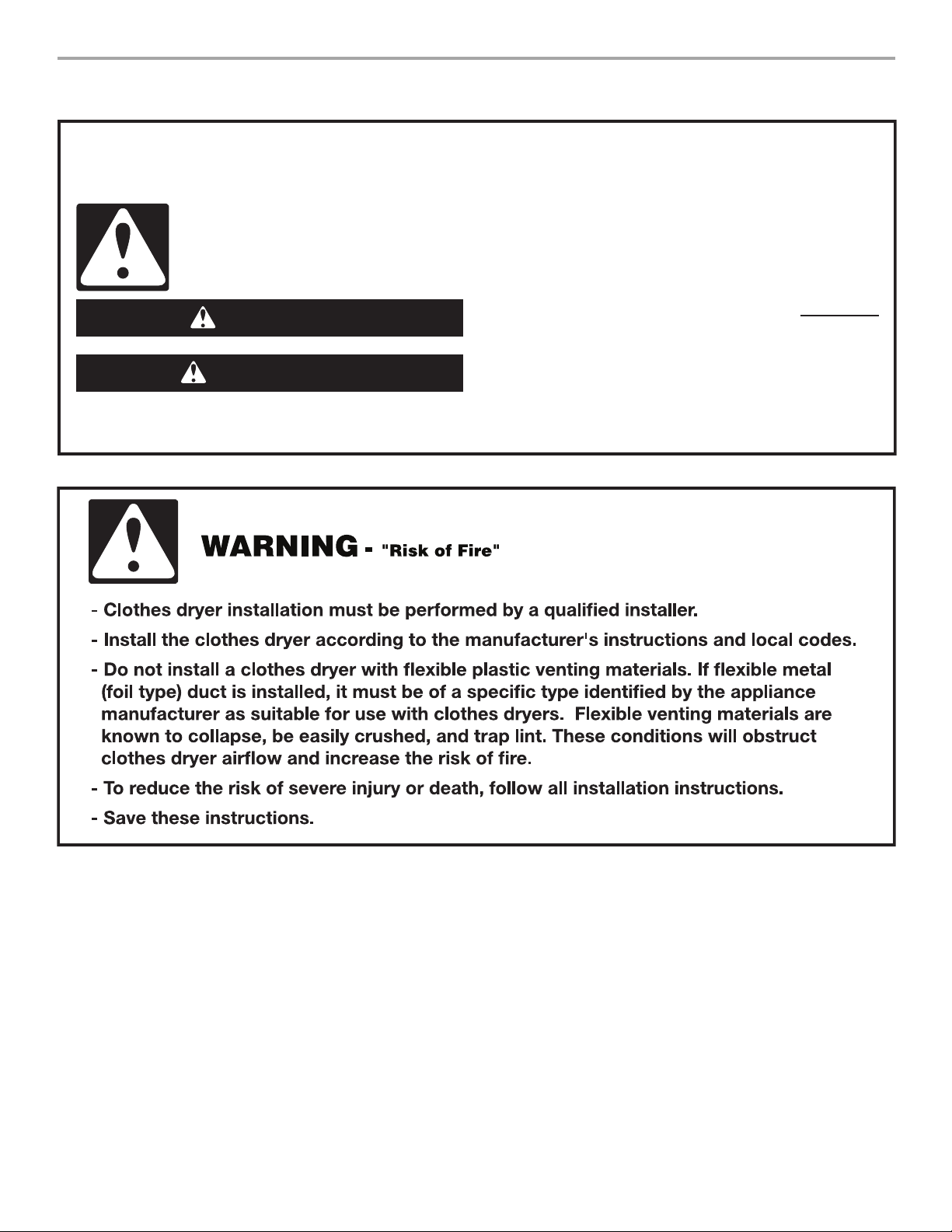
DRYER SAFETY
Your safety and the safety of others are very important.
We have provided many important safety messages in this manual and on your appliance. Always read and obey all safety
messages.
This is the safety alert symbol.
This symbol alerts you to potential hazards that can kill or hurt you and others.
All safety messages will follow the safety alert symbol and either the word “DANGER” or “WARNING.”
These words mean:
You can be killed or seriously injured if you don't immediately
DANGER
WARNING
All safety messages will tell you what the potential hazard is, tell you how to reduce the chance of injury, and tell you what can
happen if the instructions are not followed.
follow instructions.
can be killed or seriously injured if you don't
You
instructions.
follow
2
IMPORTANT: The gas installation must conform with local codes, or in the absence of local codes, with the National Fuel Gas
Code, ANSI Z223.1/NFPA 54 or the Canadian Natural Gas and Propane Installation Code, CSA B149.1.
The dryer must be electrically grounded in accordance with local codes, or in the absence of local codes, with the National
Electrical Code, ANSI/NFPA 70 or Canadian Electrical Code, CSA C22.1.
WARNING: For your safety, the information in this manual must be followed to minimize
the risk of re or explosion, or to prevent property damage, personal injury, or death.
– Do not store or use gasoline or other ammable vapors and liquids in the vicinity of this
or any other appliance.
– WHAT TO DO IF YOU SMELL GAS:
Do not try to light any appliance.
•
Do not touch any electrical switch; do not use any phone in your building.
•
Clear the room, building, or area of all occupants.
•
Immediately call your gas supplier from a neighbor's phone. Follow the gas supplier's
•
instructions.
If you cannot reach your gas supplier, call the re department.
•
– Installation and service must be performed by a qualied installer, service agency, or
the gas supplier.
WARNING: Gas leaks cannot always be detected by smell.
Gas suppliers recommend that you use a gas detector approved by UL or CSA.
For more information, contact your gas supplier.
If a gas leak is detected, follow the “What to do if you smell gas” instructions.
3
In the State of Massachusetts, the following installation instructions apply:
■
Installations and repairs must be performed by a qualied or licensed contractor, plumber, or gastter qualied or licensed by
the State of Massachusetts.
■
If using a ball valve, it shall be a T-handle type.
■
A exible gas connector, when used, must not exceed 3 feet.
INSTALLATION REQUIREMENTS
Steam Models
Tools and Parts
Gather the required tools and parts before starting installation. Read
and follow the instructions provided with any tools listed here.
For All Installations:
■ Flat-blade screwdriver
■ #2 Phillips screwdriver
■ Adjustable wrench that
opens to 1" (25 mm) or
hex-head socket wrench
(for adjusting dryer feet)
■ Level
■ Vent clamps
■ Caulking gun and compound
(for installing new exhaust
vent)
■ Tin snips (new vent
installations)
■ ¼" nut driver
(recommended)
■ Tap e me asu re
■ Pliers
Gas Installations:
■ 8" or 10" pipe wrench
■ 8" or 10" adjustable wrench
■ Pipe-joint compound
resistant to LP gas
(for gas connections)
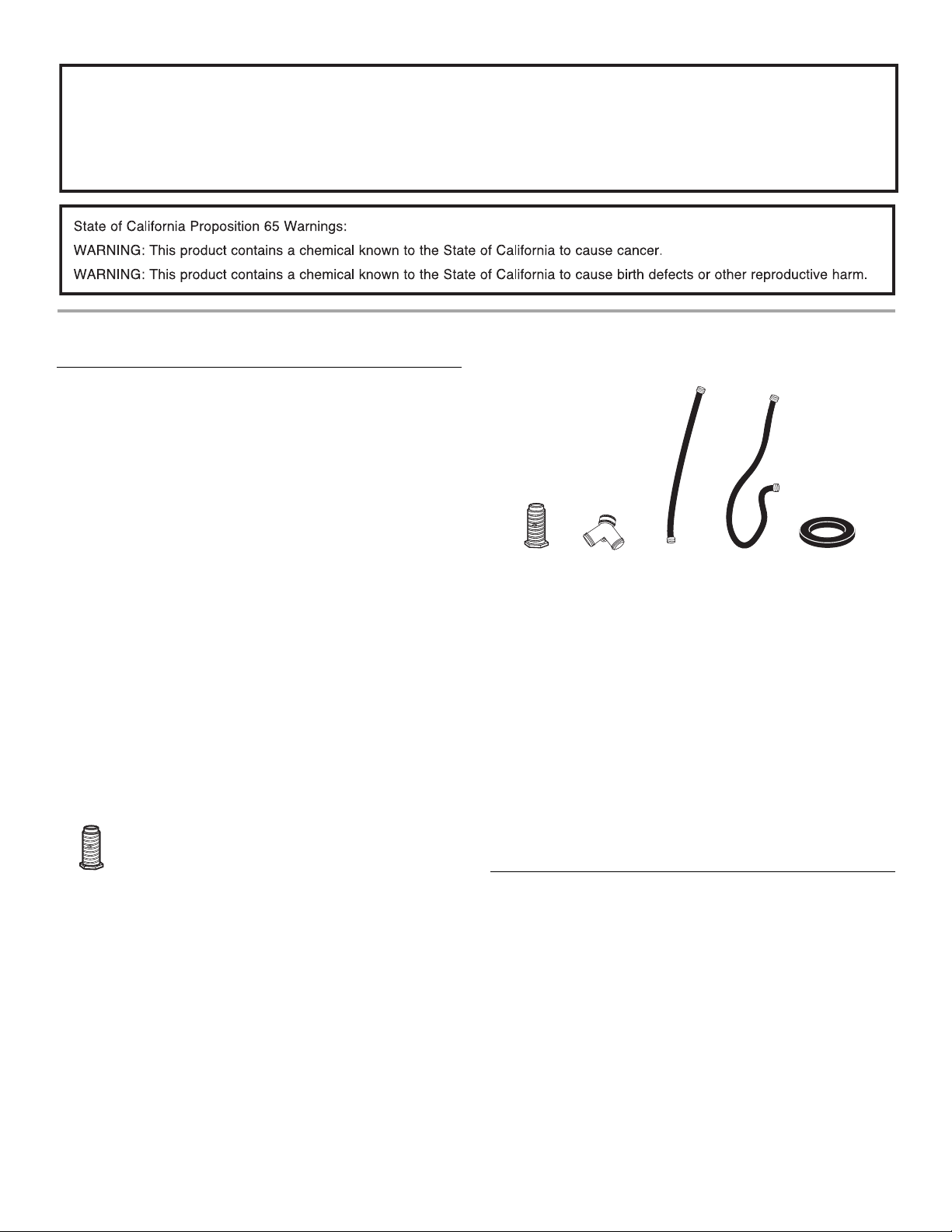
Parts supplied
Non-Steam Models
4 Leveling legs
Remove parts package from dryer drum. Check that all parts
are included.
NOTE: Do n
on a pedestal.
ot use leveling legs supplied with dryer if installing
A
A. Leveling legs (4)
B. “Y” connector
C. Short inlet hose
B
C
D. Long inlet hose
E. Rubber washer
D
E
Remove parts package from dryer drum. Check that all parts
are included.
NOTE: Do not use leveling legs supplied with dryer if installing on a pedestal.
Parts needed
Check local codes. Check existing electrical supply and venting.
See “Electrical Requirements” and “Venting Requirements” before
purchasing parts.
Mobile home installations require m
etal exhaust system hardware
available for purchase from the dealer from whom you purchased
your dryer. For further information, please refer to the “Assistance
or Service” section in your Use and Care Guide.
Optional Equipment
Refer to your Use and Care guide for information about the
accessories available for your dryer.
4
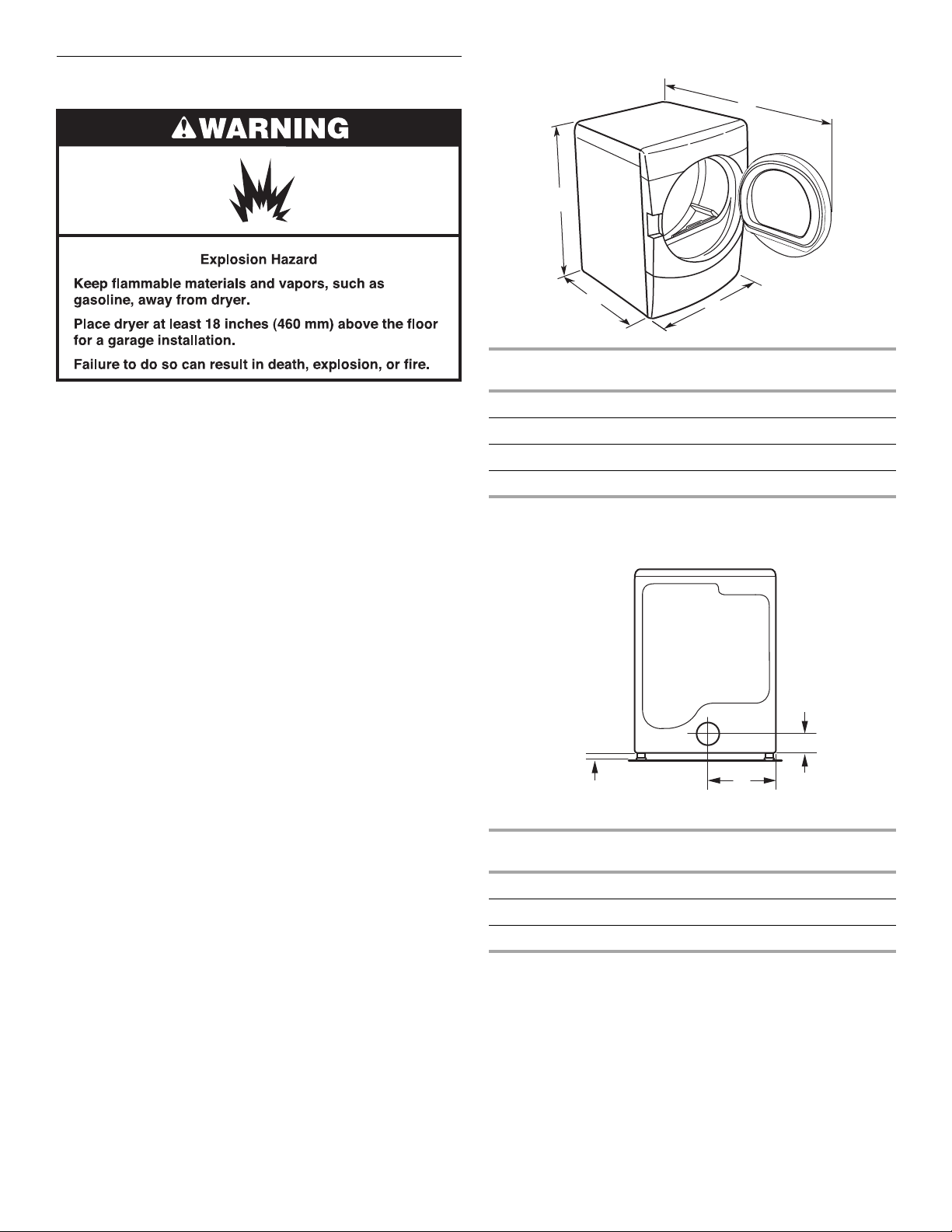
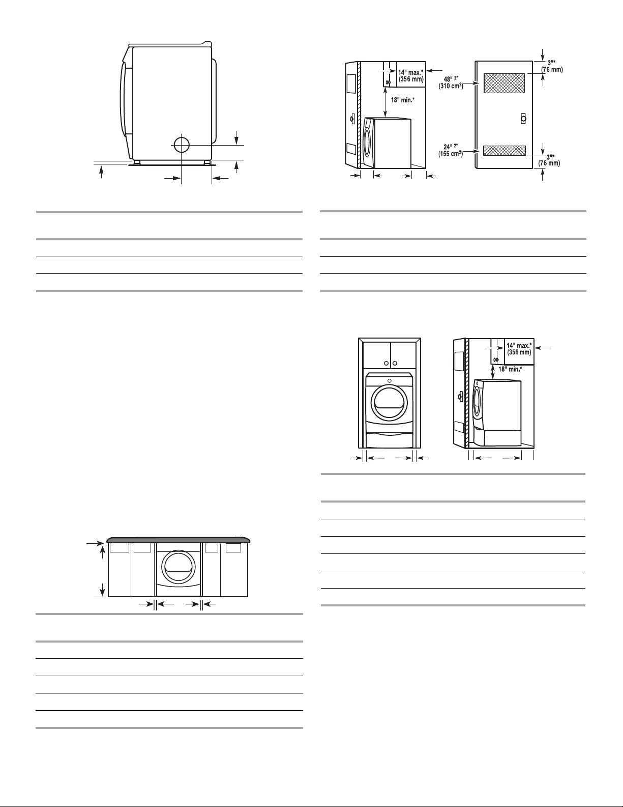
Location Requirements
Dryer Dimensions
D
A
You will need
■ A location that allows for proper exhaust installation.
See “Venting Requirements.”
■ A separate 15 or 20-amp circuit needed for gas dryers and
30-amp circuit needed for electric dryers.
■ If you are using a power supply cord, a grounded electrical
outlet located within 2 ft (610 mm) of either side of the dryer.
See “Electrical Requirements.”
■ A sturdy floor to support the total dryer weight of 200 lbs
(90.7 kg). The combined weight of a companion appliance
should also be considered.
■ A level floor with a maximum slope of 1" (25 mm) under entire
dryer. If slope is greater than 1" (25 mm), install Extended Dryer
Feet Kit, Part Number 279810. Clothes may not tumble properly
and automatic sensor cycles may not operate correctly if dryer is
not level.
■ For a garage installation, you will need to place the dryer at least
18" (460 mm) above the floor. If using a pedestal, you will need
18" (460 mm) to the bottom of the dryer.
■ Steam models only: Cold water faucets located within
4 ft (1.2 m) of the dryer, and water pressure of 20-100 psi
(137.9-689.6 kPa). You may use the cold water supply from
your washer using the “Y” connector provided.
Do not operate your dryer at temperatur
es below 45ºF (7ºC). At
lower temperatures, the dryer might not shut off at the end of an
automatic sensor cycle. This can result in longer drying times.
The dryer must not be installed or st
ored in an area where it will be
exposed to water and/or weather.
Check code requirements. Some codes limit, or
do not permit,
installation of the dryer in garages, closets, mobile homes, or
sleeping quarters. Contact your local building inspector.
No other fuel-burning appliance can be installed in the same
NOTE:
closet as a dryer.
Installation clearances
The location must be large enough to allow the dryer door to
open fully.
B
Steam
(Electric or Gas)
C
Non-Steam
(Electric or Gas)
A 38" (965 mm) 38" (965 mm)
9
B 32
/16" (827 mm) 31 1/2" (800 mm)
C 27" (686 mm) 27" (686 mm)
D 52 9/16" (1335 mm) 51 1/2" (1308 mm)
NOTE: Most installations require a minimum 5" (127 mm)
clearance behind the dryer for the exhaust vent with elbow.
Venting Dimensions
C
A*
Back View
Steam
(Electric or Gas)
A* 1" (25 mm) 1" (25 mm)
B 14" (356 mm) 14" (356 mm)
7
C 3
/16" (87 mm) 3 7/16" (87 mm)
* Dimension A is approximate, depending on when the diamond
marking on the leveling foot is no longer visible.
B
Non-Steam
(Electric or Gas)
5
A*
A
A
B
Side View
Closet installation - Dryer only
(460 mm)
C
A*
B C**
Side view
Closet door with vents
Steam
(Electric or Gas)
Non-Steam
(Electric or Gas)
A* 1" (25 mm) 1" (25 mm)
5
B 7
C 3
* Dimension
marking on the leveling foot is no longe
/8" (194 mm) 7 5/8" (194 mm)
3
/8" (86 mm) 3 3/8" (86 mm)
A is approximate, depending on when the diamond
r visible.
See “Venting Requirements.”
Installation spacing for recessed area or closet installation
The following spacing dimensions are recommended for this dryer.
This dryer has been tested for spacing of 0" (0 mm) clearance on the
sides an
following reasons:
■ Additional spacing should be considered for ease of installation
■ Additional clearances might be required for wall, door, and floor
■ Additional spacing should be considered on all sides of the dryer
■ For closet installation, with a door, minimum ventilation openings
■ Companion appliance spacing should also be considered.
Custom under
d rear. Recommended spacing should be considered for the
and servicing.
moldings.
to reduce noise transfer.
in the top and bottom of the door are required. Louvered doors
with equivalent ventilation openings are acceptable.
counter installation - Dryer only
Steam
(Electric or Gas)
Non-Steam
(Electric or Gas)
A* 1" (25 mm) 1" (25 mm)
B 32
9
/16" (827 mm) 31 1/2" (800 mm)
C** 5" (127 mm) 5" (127 mm)
*Required spacing
**For side or bottom venting, 0" (0 mm) spacing is allowed.
Recessed or cl
oset installation - Dryer on pedesta
(460 mm)
B C D* E
Steam
(Electric or G
as)
(Electric or Gas)
l
F**
Non-Steam
A 1" (25 mm) 1" (25 mm)
B 27" (686 mm) 27" (686 mm)
C 1" (25 mm) 1" (25 mm)
B
C* DE*
Steam
(Electric or Gas)
Non-Steam
(Electric or Gas)
A 0" (0 mm) 0" (0 mm)
E 32
F** 5" (127 mm) 5" (127 mm)
*Required spacing
**For side or bottom venting, 0" (0 mm) spacing is allowed
NOTE: Some
installation.
9
/16" (827 mm) 31 1/2" (800 mm)
models are not recommended for recessed or closet
B 38" (965 mm) 38" (965 mm)
C* 1" (25 mm) 1" (25 mm)
D 27" (686 mm) 27" (686 mm)
E* 1" (25 mm) 1" (25 mm)
D* 1" (25 mm) 1" (25 mm)
*Required spacing
NOTE:
Some models are not recommended for undercounter
installation.
6
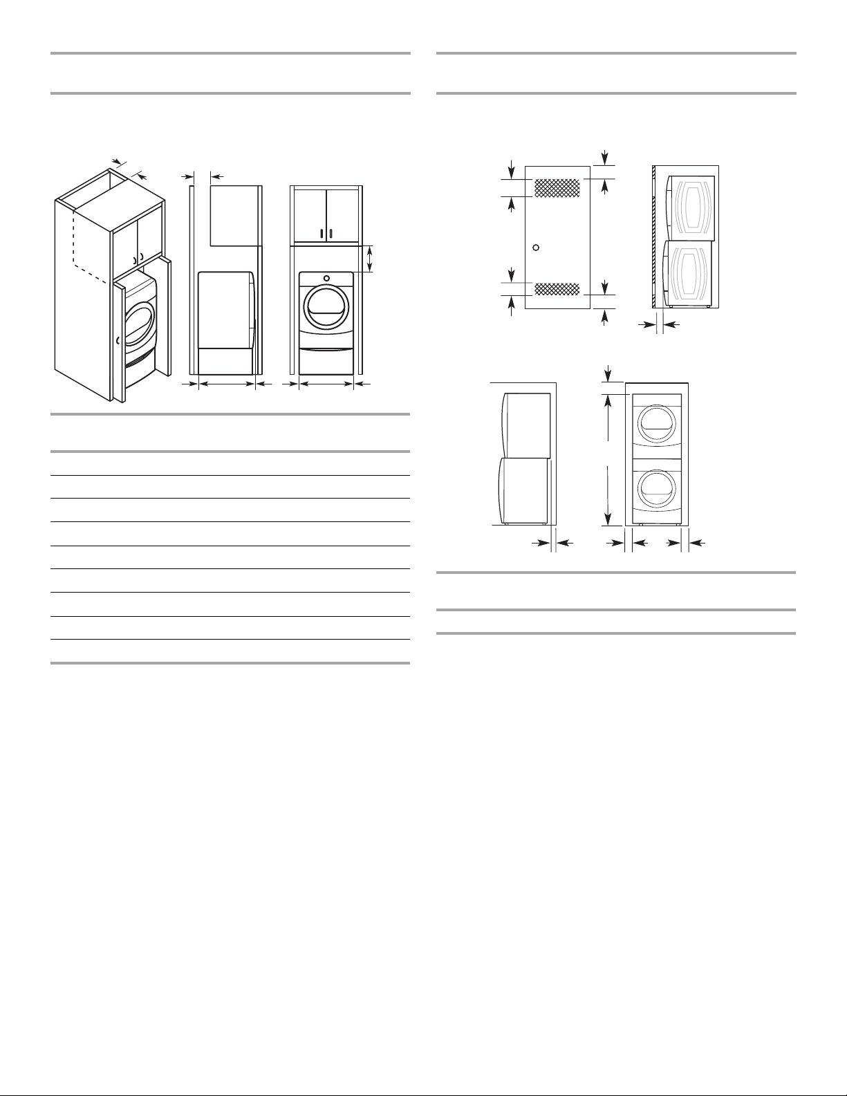
Recommended installation spacing for cabinet
installation
Recommended installation spacing for recessed or
closet installation, with stacked washer and dryer
NOTE: Some models are not recommended for cabinet installation.
■ For cabinet installation, with a door, minimum ventilation
openings in the top of the cabinet are required.
A*
B*
C*
D**
Steam
(Electric or Gas)
E
G
F*
H
Non-Steam
(Electric or Gas)
I
A* 7" (178 mm) 7" (178 mm)
B* 7" (178 mm) 7" (178 mm)
C* 9" (229 mm) 9" (229 mm)
The dimensions shown are for the recommended spacing.
48 in.2 *
2
(310 cm
)
3"* (76 mm)
3"* (76 mm)
2
24 in.
(155 cm2)
*
6"* (152 mm)
76"
(1930 mm)
1"* (25 mm)
D** 5" (127 mm) 5" (127 mm)
9
E 32
/16" (827mm) 31 1/2" (800 mm)
F* 1" (25 mm) 1" (25 mm)
G 1" (25 mm) 1" (25 mm)
H 27" (686 mm) 27" (686 mm)
I 1" (25 mm) 1" (25 mm)
*Required spacing
**For side or bottom venting, 0" (0 mm) spacing is allowed.
A*
1"
(25 mm)
27"
(686 mm)
Steam
(Electric or Gas)
1"
(25 mm)
Non-Steam
(Electric or Gas)
A* 5 ½" (140 mm) 5" (127 mm)
*Required spacing
NOTE: Some
models are not recommended for stacked recessed or
closet installation.
Mobile home - Additional installation requirements
This dryer is suitable for mobile home installations. The installation
must conform to the Manufactured Home Construction and Safety
Standard, Title 24 CFR, Part 3280 (formerly the Federal Standard for
Mobile Home Construction and Safety, Title 24, HUD Part 280) or
Standard CAN/CSA-Z240 MH.
Mobile home installations require:
All Dryers
■ Metal exhaust system hardware, which is available for purchase
from your dealer.
■ Special provisions must be made in mobile homes to introduce
outside air into the dryer. The opening (such as a nearby
window) should be at least twice as large as the dryer exhaust
opening.
For gas dryers
■ Mobile Home Installation Kit Part Number 346764. See “Tools
and Parts” section for information on ordering.
7
ELECTRIC DRYER POWER HOOKUP – CANADA ONLY
For further information, please reference the service numbers
Electrical Requirements
located in the “Assistance or Service” section
.
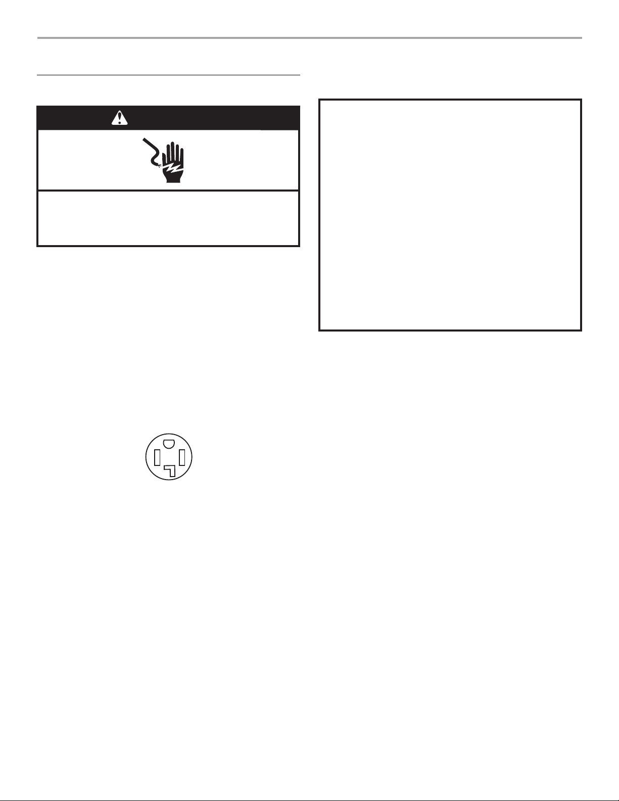
WARNING
Electrical Shock Hazard
Plug into a grounded 4 prong outlet.
Failure to do so can result in death or electrical shock.
It is your responsibility
■ To contact a qualified electrical installer.
■ To be sure that the electrical connection is adequate and in
conformance with the Canadian Electrical Code, C22.1-latest
edition and all local codes. A copy of the above codes standard
may be obtained from: Canadian Standards Association, 178
Rexdale Blvd., Toronto, ON M9W 1R3 CANADA.
■ To supply the required 4 wire, single phase, 120/240 volt,
60 Hz., AC only electrical supply on a separate 30-amp circuit,
f
used on both sides of the line. A time-delay fuse or circuit
breaker is recommended. Connect to an individual branch
circuit.
■ This dryer is equipped with a CSA International Certified Power
Cord intended to be plugged into a standard 14-30R wall
receptacle. The cord is 5 ft (1.52 m) in length. Be sure wall
receptacle is within reach of dryer’s final location.
GROUNDING INSTRUCTIONS
■
For a grounded, cord-connected dryer:
This dryer must be grounded. In the event of malfunction or
breakdown, grounding will reduce the risk of electric shock
by providing a path of least resistance for electric current.
This dryer is equipped with a cord having an equipmentgrounding conductor and a grounding plug. The plug must
be plugged into an appropriate outlet that is properly
installed and grounded in accordance with all local codes
and ordinances.
WARNING: Improper connection of the equipment-
grounding conductor can result in a risk of electric shock.
Check with a qualied electrician or service representative
or personnel if you are in doubt as to whether the dryer is
properly grounded. Do not modify the plug provided with
the dryer: if it will not t the outlet, have a proper outlet
installed by a qualied electrician.
SAVE THESE INSTRUCTIONS
4-wire receptacle 14-30R
If using a replacement power supply cord, it is recommended that
you use Power Supply Cord Replacement Part Number 9831317.
8
GAS DRYER POWER HOOKUP
Gas Supply Requirements
WARNING
Explosion Hazard
Use a new CSA International approved gas supply line.
Install a shut-off valve.
Securely tighten all gas connections.
If connected to LP, have a qualied person make sure
gas pressure does not exceed 13" (330 mm) water
column.
Examples of a qualied person include:
licensed heating personnel,
authorized gas company personnel, and
authorized service personnel.
Failure to do so can result in death, explosion, or re.
■ If your dryer has been converted to use LP gas,
3
/8" LP
compatible copper tubing can be used. If the total length of the
supply line is more than 20 ft (6.1 m), use larger pipe.
NOTE: Pipe-joint compounds that resist the action of LP gas
must be used. Do not use TEFLON
■ Must include a shutoff valve:
®†
tape.
In the U.S.A.:
An individual manual shutoff valve must be installed within six (6)
feet (1.8 m) of the dryer in accordance with the National Fuel
Gas Code, ANSI Z223.1.
In Canada:
An individual manual shutoff valve must be
installed within six(6)
feet (1.8 m) of the dryer in accordance with the B149.1, Natural
Gas and Propane Installation Code.
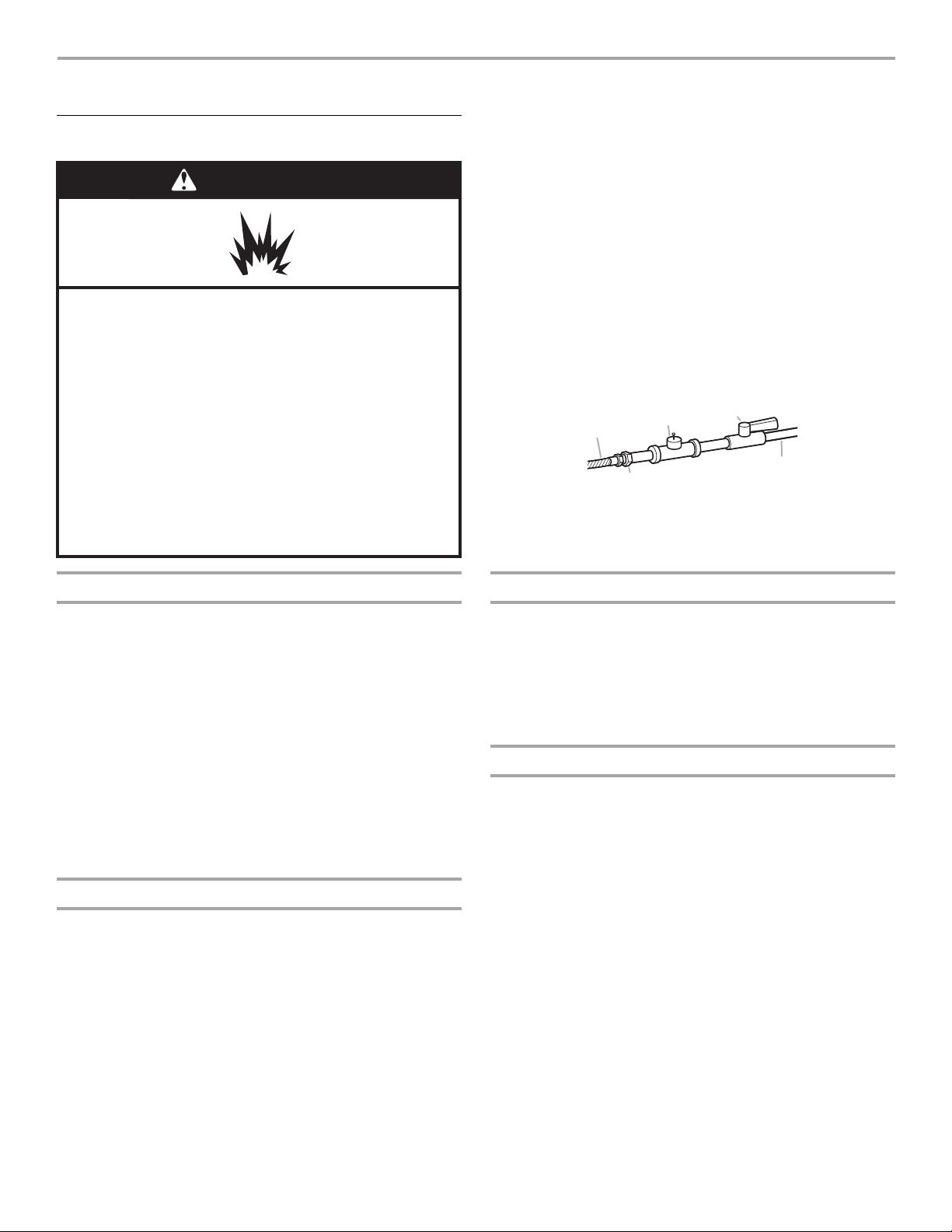
The location should be easy to reach for opening and closing.
A
A.3/8" flexible gas connector
3
B.
/8" pipe to flare adapter
fitting
C
B
E
D
1
/8" NPT minimum plugged
C.
tapping
1
/2" NPT gas supply line
D.
E. Gas shutoff valve
Gas Type
Natural gas:
This dryer is equipped for use with Natu
ral gas. It is design-certified
by CSA International for LP (propane or butane) gases with
appropriate conversion.
■ Your dryer must have the correct burner for the type of gas in
your home. Burner information is located on the rating plate in
the door well of your dryer. If this information does not agree
with the type of gas available, contact your dealer or call the
phone numbers referenced in the “Assistance or Service”
section.
LP gas conversion:
Conversion must be m
No attempt shall be made to con
ade by a qualified technician.
vert the appliance from the gas
specified on the model/serial rating plate for use with a different gas
without consulting your gas company.
Gas supply line
■ Must include
for test gauge connection, immediately upstream of the gas
con
nection to the dryer. See illustration.
1
■
/2" IPS pipe is recommended.
3
■
/8" approved aluminum or copper tubing is acceptable for
lengths under 20 ft (6.1 m) if local codes and gas supplier
permit.
■ If you are using Natural gas, do not use copper tubing.
■ Lengths over 20 ft (6.1 m) should use larger tubing and a
different size adapter fitting.
1
/8" NPT minimum plugged tapping accessible
Gas supply connection requirements
■ Use an elbow and a
the flexible gas connector and the dryer gas pipe, as needed to
avoid kinking.
■ Use only pipe-joint compound. Do not use TEFLON
■ This dryer must be connected to the gas supply line with a listed
flexible gas connector that complies with the standard for
connectors for gas appliances, ANSI Z21.24 or CSA 6.10.
3
/8" flare x 3/8" NPT adapter fitting between
®†
tape.
Burner input requirements
Elevations above 10,000 ft (3,048 m):
■ When installed above 10,000 ft (3,048 m) a 4% reduction of the
burner Btu rating shown on the model/serial number plate is
required for each 1,000 ft (305 m) increase in elevation.
Gas supply pressure testing
■ The dryer must be disconnected from the gas supply piping
system during pressure testing at pressures greater than ½ psi.
†
®TEFLON is a registered trademark of E.I. Du Pont De Nemours and Company.
9
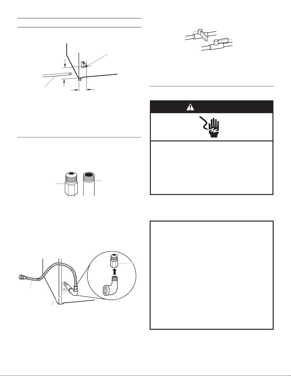
Dryer gas pipe
3. Open the shutoff valve in the supply line. The valve is open when
the handle is parallel to the gas pipe.
■ The gas pipe that comes out through the rear of your dryer has a
3
/8" male pipe thread.
A
*6¼"
(159 mm)
A.1/2" NPT gas supply line
3
B.
/8" NPT dryer pipe
1½"
(38 mm)
B
*NOTE: If the dryer is mounted on a pedestal, the gas pipe
height must be an additional 10" (254 mm) or 15.5" (394 mm)
fr
om the floor, depending on the pedestal model. For a garage
installation, the gas pipe height must be an additional
18" (457 mm) from the floor.
Make Gas Connection
1. Remove the red cap from the gas pipe.
2. Usin
g a wrench to tighten, connect the gas supply to the dryer.
Use pipe-joint compound on the threads of all non-flared male
fittings. If flexible metal tubing is used, be sure there are no kinks.
A
B
A
B
A. Closed valve
B. Open valve
4. Test all connections by brushing on an approved noncorrosive
leak-detection solution. Bubbles will show a leak. Correct any
leak found.
Electrical Requirements
WARNING
Electrical Shock Hazard
Plug into a grounded 3 prong outlet.
Do not remove ground prong.
Do not use an adapter.
Do not use an extension cord.
Failure to follow these instructions can result in death,
re, or electrical shock.
A. Flared male fitting
B. Non-flared male fitting
NOTE: For LP gas connections, you must use pipe-joint
compound resistant to the action of LP gas. Do not use
TEFLON
®†
tape.
A combination of pipe fittings must be used to connect the dryer
e existing gas line. Shown is a recommended connection.
to th
Your connection may be different, according to the supply line
type, size and location.
D
A
B
A.3/8" flexible gas
connector
3
/8" dryer pipe
B.
3
C.
/8" to 3/8" pipe elbow
3
D.
/8" pipe-to-flare
adapter fitting
C
■ 120 Volt, 60 Hz., AC only, 15- or 20-amp fused electrical
supply is required. A time-delay fuse or circuit breaker is
recommended. It is also recommended that a separate circuit
serving only this dryer be provided.
GROUNDING INSTRUCTIONS
■
For a grounded, cord-connected dryer:
This dryer must be grounded. In the event of malfunction or
breakdown, grounding will reduce the risk of electric shock
by providing a path of least resistance for electric current.
This dryer is equipped with a cord having an equipmentgrounding conductor and a grounding plug. The plug must
be plugged into an appropriate outlet that is properly
installed and grounded in accordance with all local codes
and ordinances.
WARNING: Improper connection of the equipment-
grounding conductor can result in a risk of electric shock.
Check with a qualied electrician or service representative
or personnel if you are in doubt as to whether the dryer is
properly grounded. Do not modify the plug provided with
the dryer: if it will not t the outlet, have a proper outlet
installed by a qualied electrician.
SAVE THESE INSTRUCTIONS
†
®TEFLON is a registered trademark of E.I. Du Pont De Nemours and Company.
10
 Loading...