

Amana NGD5800TQ, NGD5500TQ, NGD5400TQ, NGD5240TQ, NGD5200TQ Dimension Guide
...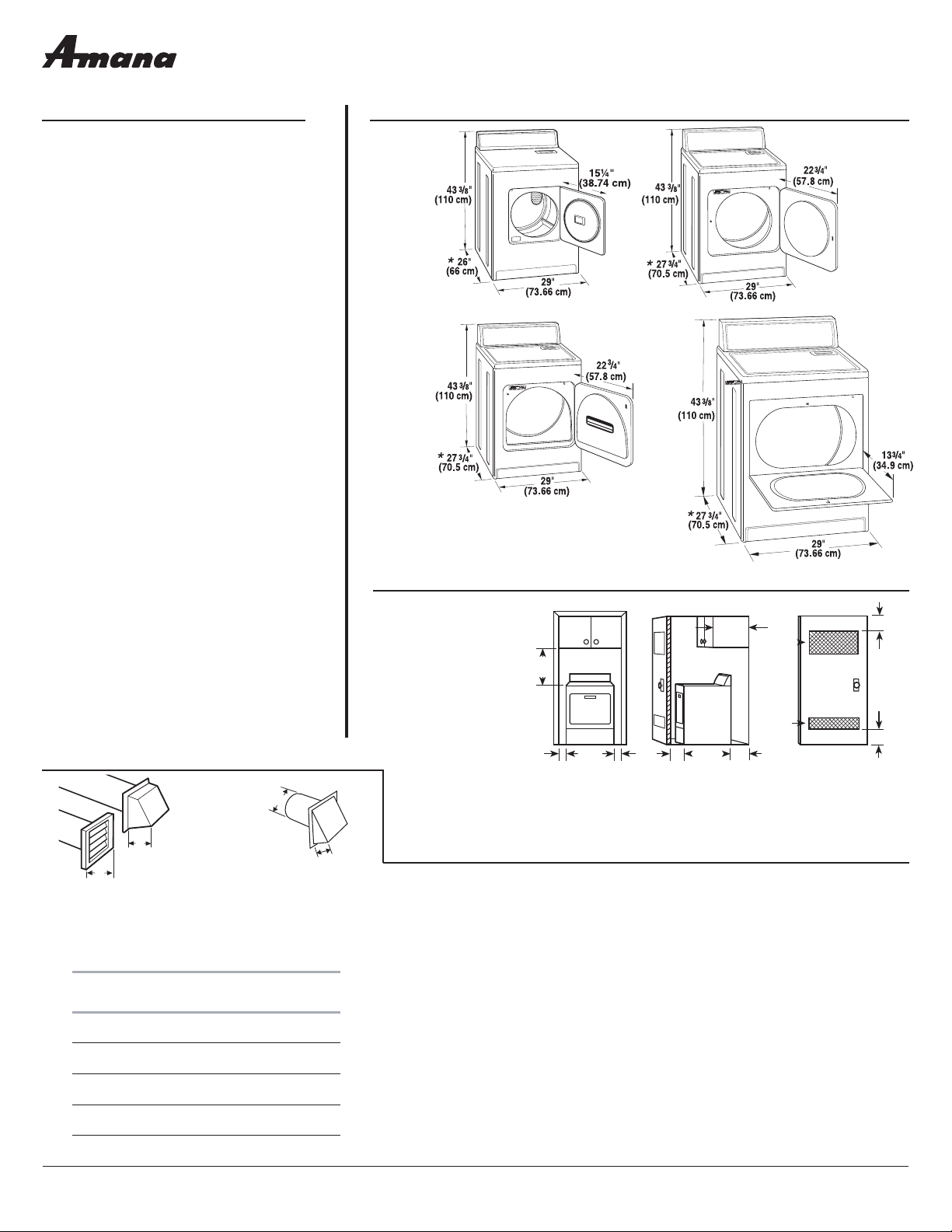
29" (73.7 cm) Gas Dryer
PRODUCT MODEL NUMBERS PRODUCT DIMENSIONS
RECESSED AREA AND CLOSET INSTALLATION
EXHAUST VENTING
NGD5100T
NGD5200T
NGD5240T
NGD5400T
NGD5500T
NGD5800T
NGD4500V
NGD4800V
Because Whirlpool Corporation policy includes a continuous commitment to improve
our products, we reserve the right to change materials and specifications without notice.
Dimensions are for planning purposes only. For complete details, see Installation
Instructions packed with product. Specifications subject to change without notice.
Ref. W10150630B
09-11-08
A
B
C
18"*
(45.7 cm)
1"
(2.5 cm)
29"
(73.66 cm)
1"
(2.5 cm)
1"*
(2.5 cm)
14" max.*
(35.6
cm)
27¾"
(70.5 cm)
5"*
(12.7 cm)
48 in.
(310 cm )
2
*
2
24 in.
(155 cm )
2
*
2
3"*
(7.6 cm)
3"*
(7.6 cm)
For closet installation
with a door, minimum
ventilation openings in
the top and bottom of
the door are required.
Louvered doors with
equivalent ventilation
openings are acceptable.
1. Select the route that will provide the straightest and most direct path outdoors. Plan
the installation to use the fewest number of elbows and turns. When using elbows or
making turns, allow as much room as possible. Bend vent gradually to avoid kinking.
Avoid 90° turns.
2. Determine vent length.
The maximum length of the exhaust system depends upon:
• The type of vent (rigid metal or flexible metal).
• The number of elbows used.
• Type of hood.
See the exhaust vent length chart that matches your hood type for the maximum vent
lengths you can use.
3. Determine the number of elbows you will need.
IMPORTANT: Do not use vent runs longer than specified in the Vent Length Chart.
In the column listing the type of metal vent you are using (rigid metal or flexible metal),
find the maximum length of metal vent on the same line as the number of elbows.
Vent Length Chart
Number of
90° turn s
or elbows
Type of
vent
Box or
Louvered
hoods
Angled
hoods
0 Rigid metal
Flexible metal
64 ft (20 m)
36 ft (11 m)
58 ft (17.7 m)
28 ft (8.5 m)
1 Rigid metal
Flexible metal
54 ft (16.5 m)
31 ft (9.4 m)
48 ft (14.6 m)
23 ft (7 m)
2 Rigid metal
Flexible metal
44 ft (13.4 m)
27 ft (8.2 m)
38 ft (11.6 m)
19 ft (5.8 m)
3 Rigid metal
Flexible metal
35 ft (10.7 m)
25 ft (7.6 m)
29 ft (8.8 m)
17 ft (5.2 m)
4 Rigid metal
Flexible metal
27 ft (8.2 m)
23 ft (7 m)
21 ft (6.4 m)
15 ft (4.6 m)
Gas supply: Dryer is equipped for use with
Natural gas. Dryer can be converted to L.P. gas.
When rigid pipe is used it should be 1/2" IPS.
When acceptable to the gas supplier and local
codes, 3/8" approved aluminum or copper tubing
may be used for lengths under 20 ft (6.1 m). For
lengths more than 20 ft (6.1 m), larger tubing and
a different size adapter fitting should be used.
Pipe-joint compounds resistant to the action of
L.P. gas must be used. Do not use TEFLON
®
†
tape.
If local codes permit, it is recommended that new
flexible metal tubing, design-certified by CSA, be
used for connecting the appliance to the rigid gas
supply line. (The gas pipe which extends through
the lower rear of the appliance has 3/8" male pipe
thread.) An individual manual shutoff valve must
be installed within 6 ft (1.8 m) of the dryer in
accordance with the National Fuel Gas Code ANSI
Z223.1.
Electrical: A 120-volt, 60-Hz, AC-only, 15- or
20-amp, fused electrical supply is required. A
time-delay fuse or circuit breaker is recommended.
It is recommended that a separate circuit serving
only this dryer be provided.
Exhaust venting: Exhaust your dryer to the
outside. 4" (10.2 cm) vent is required. Rigid or
flexible metal exhaust vent must be used. Do Not
use plastic or metal foil vent. Exhaust outlet hood
must be at least 12" (30.5 cm) from the ground or
any object that may be in the path of the exhaust.
†®TEFLON is a registered trademark of E.I. Du Pont De
Nemours and Company.
A. Small Opening
Side-Swing Door
B. Large Opening
Side-Swing Door
A. Recessed area
B. Side view - closet or confined area
C. Closet door with vents
C. Wide Opening
Side-Swing Door
D. Wide Opening
Hamper Door
A
B
C
D
NOTE: Side and bottom exhaust installations have a
90º turn inside the dryer. To determine maximum
exhaust length, add one 90º turn to the chart.
4"
(10.2 cm)
2.5"
(6.4 cm)
4"
(10.2 cm)
4"
(10.2 cm)
Box hood style
Angled hood style
*Required spacing
®
 Loading...