

Page 1
PTAC
NSTALLA TION INSTRUCTIONS
I
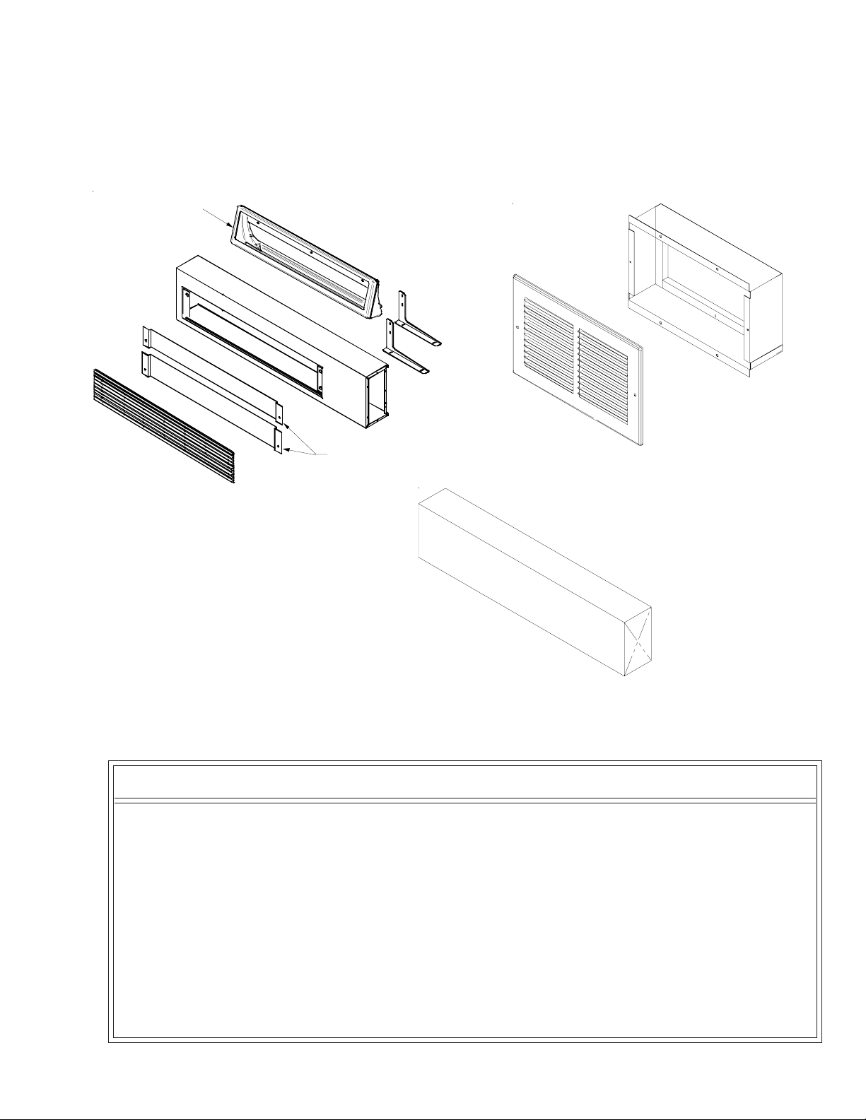
Extends air distribution to an adjoining room.
The kit consists of a main duct for the room of origin and an extension duct to reach the adjoining room, and terminal
duct. NOTE: All required hardware is provided within kit.
TRANSITION
BAFFLES
DUCT KIT
*
*
*
*
*
*
*
*
Terminal Duct Kit - TDK02
Main Duct Kit - MDK02
Extension Duct Kit - EDK02
ATTENTION INSTALLING PERSONNEL
As a professional installer you have an obligation to know the product better than the customer. This
includes all safety precautions and related items.
Prior to actual installation, thoroughly familiarize yourself with this Instruction Manual. Pay special
attention to all safety warnings. Often during installation or repair it is possible to place yourself in a
position which is more hazardous than when the unit is in operation.
Remember, it is your responsibility to install the product safely and to know it well enough to be able to
instruct a customer in its safe use.
Safety is a matter of common sense...a matter of thinking before acting. Most dealers have a list of
specific good safety practices...follow them.
The precautions listed in this Installation Manual are intended as supplemental to existing practices.
However, if there is a direct conflict between existing practices and the content of this manual, the
precautions listed here take precedence.
Part No. 1 1 1 13404
Printed in USA
September 2004
Page 2
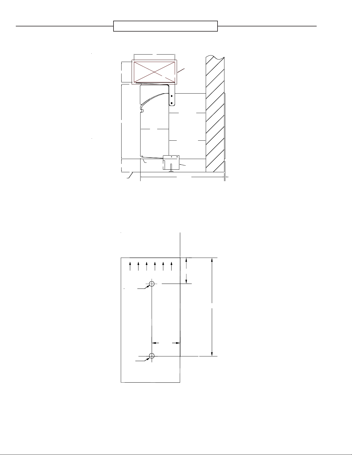
Installation Dimensions
10"
END OF
UNIT FRONT
7-1/2"
BOTTOM OF
WALL SLEEVE
DUCT
EXTENSION
5"
1/2"
TRANSITION
18-3/8"
3-1/4" MIN
FLOOR LINE
Installation Dimensions
INNER WALL
CUT-OUT
2-3/8" MIN
(FOR DUCT KIT)
WALL SLEEVE
2-3/4" MIN
(FOR SUBBASE KIT)
SUBBASE KIT
20-1/2" MAX
OUTSIDE
WALL
1/4" MIN
TOP
5/8"
Ø 1/8"
11/16"
Ø 1/8"
Hole Placement Template
2 3/8"
2
Page 3
MDK Installation Instructions
WARNING
T o avoid the risk of personal injury or death due to electrical shock, disconnect power
source before removing the chassis.
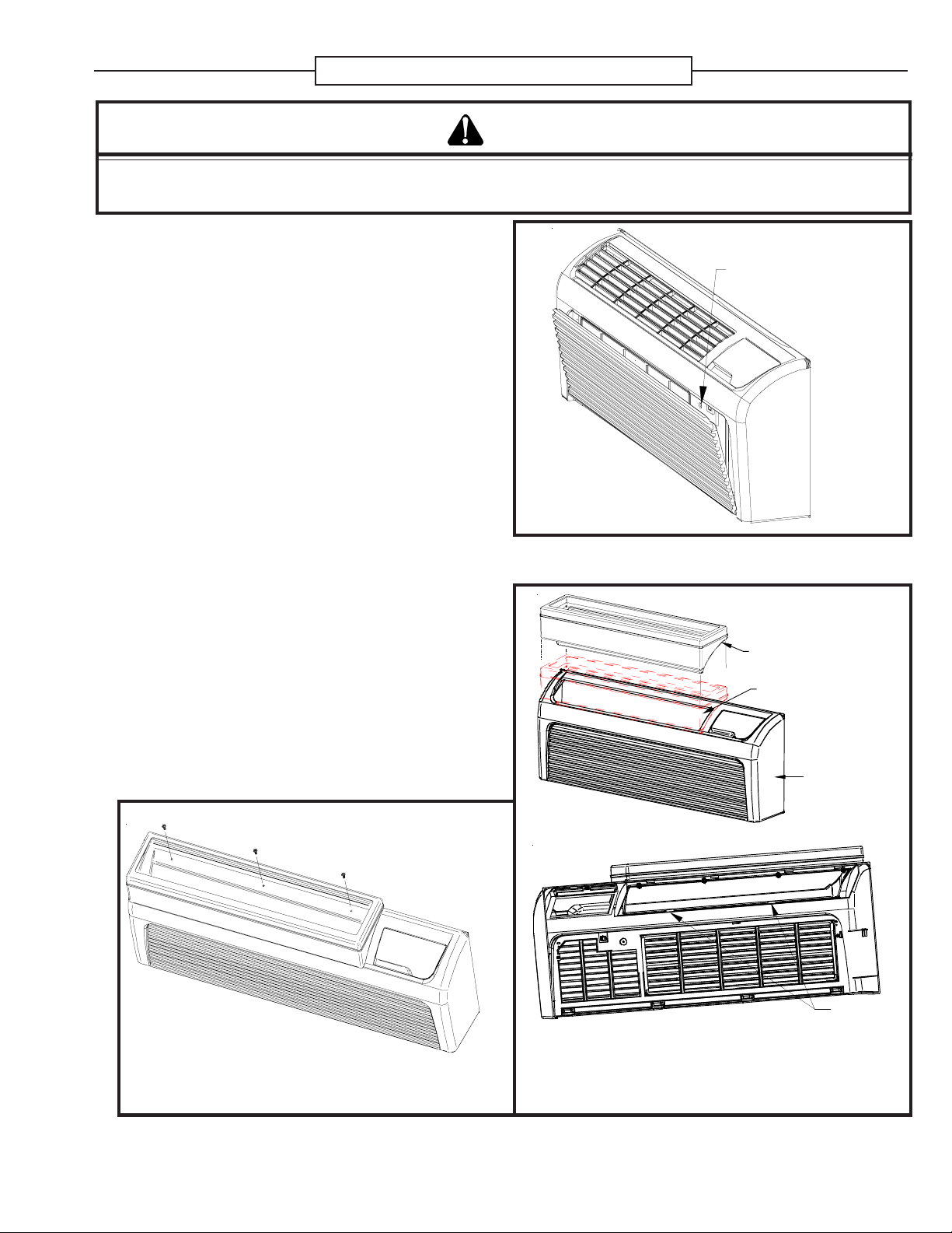
PRE-ASSEMBLY [TRANSITION/FRONT]
1. If the cabinet front is screwed to the chassis, remove
the screw located behind the inlet grille. Pull the inlet
grille forward from the top of the grille to access two
screws.
2. Remove cabinet front from chassis by tilting the bottom of the front forward, lifting slightly up and forward.
3. Disengage discharge grille from cabinet front by removing four pal nuts from under the front
FRONT MOUNTING
HOLE
4. Place transition in air discharge opening of cabinet
front and secure with the provided U-clip.
5. Using 1/8” drill bit, pre-drill holes in front using the actual transition as a template. Fasten with three
screws. Do not overtighten.
Cabinet Front Removal
TRANSITION
AIR DISCHARGE
OPENING
CABINET
FRONT
`
Transition Assembly
3
U-CLIP
Page 4

MDK Installation Instructions
PRE-ASSEMBLY
(WALL SLEEVE) HOLE DIMENSION AND PLACEMENT
1. Unplug and remove chassis from wall sleeve. Drill two
1/8” holes on left and right sides of wall sleeve in
proper locations (see template on page 2).
2. Install chassis back into wall sleeve.
3. Install transition/front assemby on to chassis. Make
sure top of cabinet front catches metal flange on
chassis.
NOTE: If there is not enough clearance between
sleeve and partition wall to drill the holes, layout
and drill the holes from inside the sleeve.
1/8" HOLES
WALL
1/8" HOLES
WALL
SLEEVE
5/8"
2-3/8"
11/16"
INDOOR
5/8"
2-3/8"
11/16"
INDOOR
SLEEVE
Wall Sleeve Hole Placement
MDK ASSEMBLY
Determine if the duct is to be extended to the right of the
unit (where controls are located) or to the left of the unit
(opposite the controls).
For left side extensions remove the main duct end cap
and reinstall on the right end of the duct. Using the four
painted sheetmetal screws, secure the two mounting
brackets to the main duct.
Two mounting slots are provided in each bracket. To
mount extension on right side, adjust bracket so the
screws are in left side of bracket slots; for mounting
extension on the left, adjust brackets so the screws are
in right side of slots.
On right side extensions shift the brackets to the right.
For left side extensions shift the brackets to the left.
Mounting Brackets Installation
LEFT SHIFT
RIGHT SH IFT
4
Page 5

Air Baffle Installation Instructions
1. Determine amount of air desired at main duct and at
extension duct. Using the table provided, select the
appropriate baffle.
DISCHARGE
AIR GRILLE
BAFFLE DIMENSIONS
AIRFLOW
MAIN DUCT EXT. DUCT
Small 3 11/16" x 31 3/4" 80% 20%
Large 4 5/16" x 31 3/4" 65% 35%
Table 1
2. Place baffle on grille support brackets on main duct.
Ensure the two extruded holes of the baffle are on top
of the front bracket holes.
3. Install discharge air grille on top of the air baffle. Secure the grille to the duct with pal nuts (provided) by
reaching through the opening in the bottom of the
duct.
4. Place main duct assembly on the transition. Secure
the brackets to the wall sleeve with four #10 hex head
screws. Do not apply pressure on top of duct during
this installation!
SUPPORT
BRACKETS
Air Grille Installation
M
D
K
T
R
A
AIR BAFFLE
A
S
S
E
M
B
L
Y
N
S
I
T
I
O
N
5. Install two Phillips head screws into the top flange of
the main supply duct at extension duct connection.
Do not tighten screws. Leave space for one thickness
of the duct sheet metal between screw head and
main duct flange.
NOTE: Total length of duct extension assembly, including field
supplied duct between main and extension duct, should not exceed
15 effective feet (according to ASHRAE standards). For additional
dimensions, refer to Main Duct and Duct Extension Dimensions
illustration.
MDK Installation Onto Transition Assembly
Main Supply Duct Top Flange
5
Page 6

Air Baffle Installation Instructions
6. In the room where the main duct kit is attached to the
chassis, cut a hole in the wall at the same height from
the floor that the main duct is located. Cut the hole 1/
8” larger than the width and height (10” x 5”) dimensions of the extension duct.
7. Measure from the end of the main duct where the extension duct will be connected to the hole in the wall.
If necessary cut the extension duct to a length where
the cut end protrudes into the wall’s inner space and
one inch from the adjoining room’s wall surface.
8. Insert the extension duct into the opening in the wall.
Install the extension duct by placing the slotted flange
over the two screws in the main duct. Using two #8
round Phillips head screws, mount bottom of extension duct to mounting bracket through the bracket slot
(see Main Supply Duct Top Flange illustration).
NOTE: The EDK02 can be cut into two sections and
used with two MDK02s if the needed length does not
exceed 21-1/4”.
PARTITION
WALL
DUCT
TERMINATION
AIR FLOW
1" to
adjoining
wall
surface
KIT
BRACKET
42-27/32" 6" TO 42-1/2"
AIR FLOW
5"
TRANSITION
DUCT
MAIN DUCT
DUCT EXTENSION
BRACKET
MINIMUM
5"
BOTH SIDES
Main Duct and Duct Extension Dimensions
6
Page 7

TDK Installation Instructions
IMPORTANT NOTE
ANY FIELD-SUPPLIED GRILLE, MUST HAVE FIXED LOUVERS THAT CANNOT BE CLOSED.
The sheet metal collar of the terminal duct kit must be mounted in the wall of the adjoining room opposite the room
where the main duct kit is attached to the PTAC chassis.
1. Cut a hole in the wall of the adjoining room such that
the hole is centered on the extension duct that is currently in the wall of the opposite room. See wall hole
dimensions illustration for sheet metal collar.
2. Insert the sheet metal collar into the wall so that the
flanges will mount flush to the wall after the collar is
pushed all the way into the wall. While pushing the
collar into the wall make sure the extension duct is inside the collar. Use four #8 screws to attach metal
collar to wall.
11-1/4"
6-1/4"
Wall Hole Dimension
11"
GASKET
6"
3. Center the metal grille over the sheet metal collar and
use two #8 screws (provided) to attach the grille to
the metal collar .
Sheet Metal Collar
USE
TWO
#8 SCREWS
Metal Grille
7
 Loading...