

Page 1

IC6 and IC6A
Ice Maker Kits
Installation and
Operating
Instructions
Introduction 2
Safety Instructions 2
Tools 3
Materials 3
Parts 4
Installation Instructions 6
Operating Instructions 13
Before Calling for Service 14
Consumer Information Line
1-800-843-0304
1
Page 2
Introduction
Safety Instructions
RECOGNIZE THIS
SYMBOL AS A SAFETY
PRECAUTION
Caution
To avoid personal injury or
property damage, observe all
safety instructions.
Read entire manual before installing kit. All
necessary tools and materials must be available
prior to installation. Verify all listed parts are
included in kit. If parts are missing, contact
dealer from whom kit was purchased.
Important
1. Mechanical experience is required to
install kit.
2. Depending on installer’s knowledge and
skill, installation can take from three to
six hours.
3. If unable to solve a problem during
installation, contact an authorized
Amana servicer. Service is at owner’s
expense.
WARNING
To avoid electrical shock which
can cause severe personal
injury or death, unplug power
cord oropen household circuit
breaker to refrigerator before
moving or servicing refrigerator.
After moving or servicing
refrigerator, reconnect power.
Caution
To avoid property damage,
observe the following:
1. Check for water leaks
prior to returning
refrigerator to normal
location.
2. Start tubing nuts by
hand to avoid cross
threading. Finish
tightening nuts
using an adjustable
wrench or 1/2" open-end
wrench. Do not over
tighten.
3. Check carefully for
water leaks 24 hours
after installation.
2
Page 3
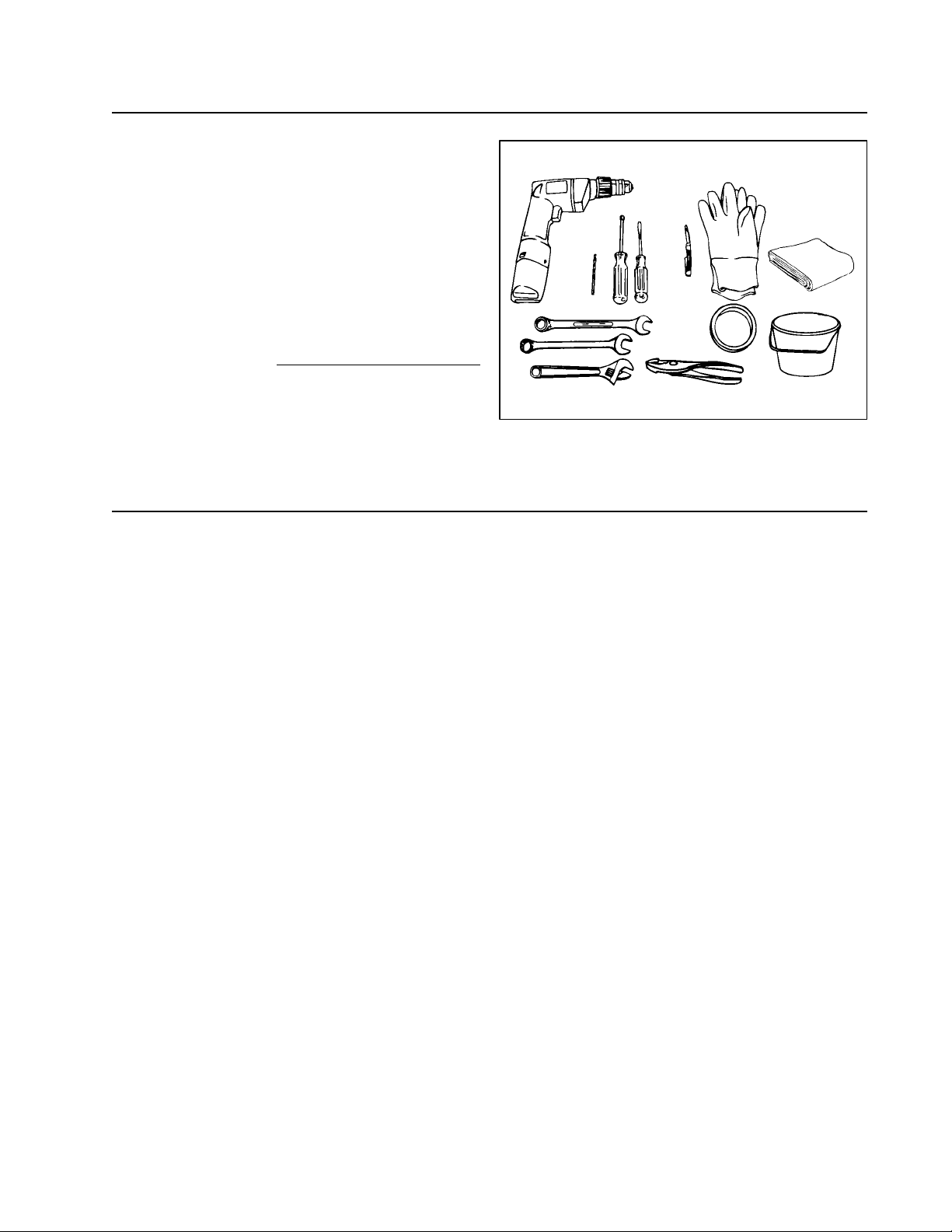
Tools
3/8" electric drill (gournd fault protected)
3/8" drill bit
1/4" hex socket and driver
1/2" open-end wrench (2)
Adjustable wrench
Flat blade screwdriver
Pliers
Small knife
Masking tape
Bucket
Towel
Tightly fitting gloves
Materials
1/4" flexible copper tubing*.
*Length of copper tubing must reach from water
supply connection plus an additional 8' for
service loop behind refrigerator. Tubing should
be soft instead of rigid and ends should be free
of burrs.
Important
Before installing ice maker, contact a plumber
to connect copper tubing to household
plumbing in compliance with local codes and
ordinances. Warranty will be void if
installation is improper or a self piercing
valve is used.
3
Page 4

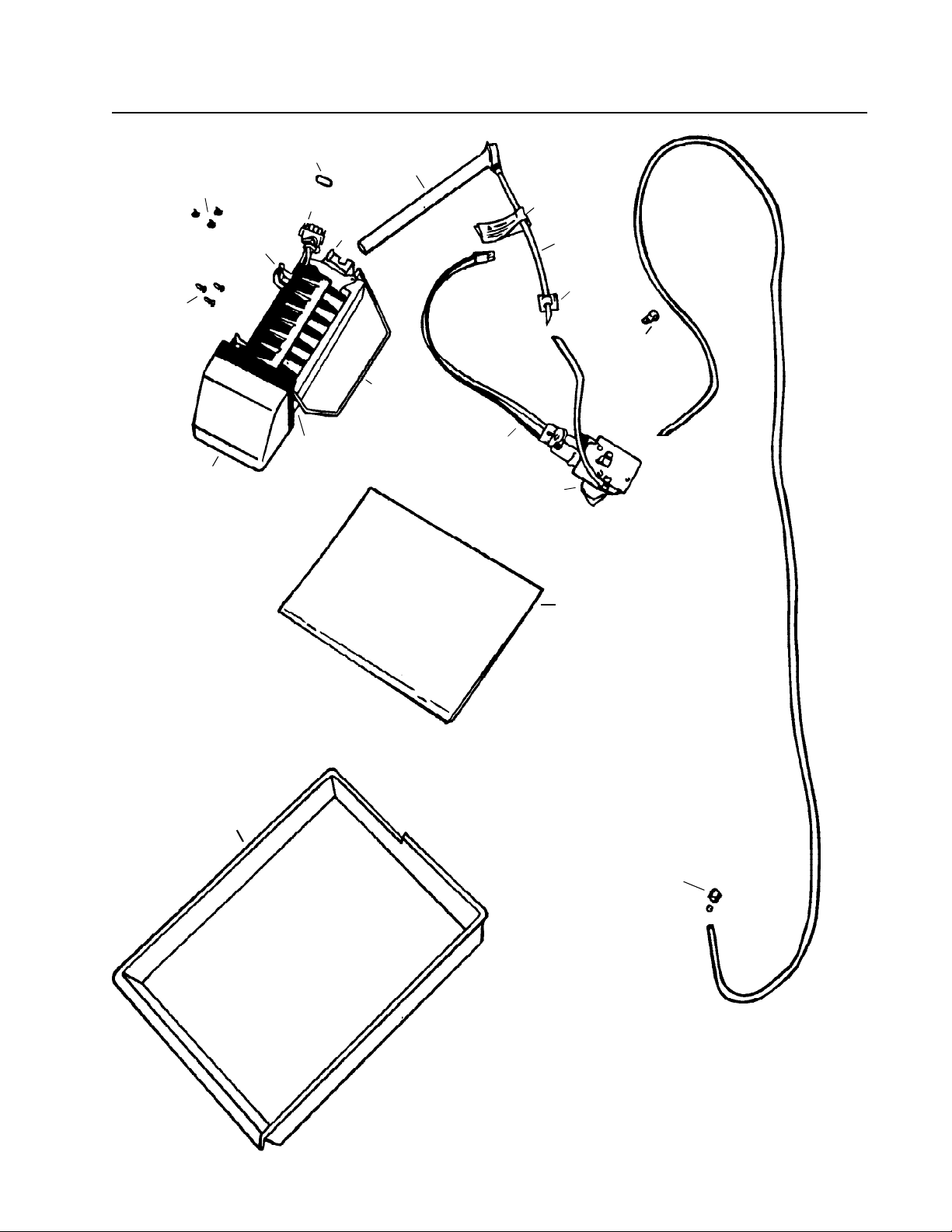
Parts
Use listed part numbers only when ordering replacement parts. Part numbers are not used in
installation instructions.
1
2
N/S
N/S
3
4
N/S
N/S
5
6
7
8
N/S
9
10
11
12
13
14
N/S
15
N/S
N/S
N/S
16
17
18
19
Description
Ice maker
Ice maker cover
Warning label
Diagnostic label
Label
Ice maker arm
Lower mounting bracket
3/8" sheet metal screw
Stainless steel clip
Water fill tube elbow
Ice maker wire harness
Ice maker wire harness clamp
Thermal fuse clip
5/8" sheet metal screw
Button plug
Oblong plug
Ice storage bucket
Water valve
Water valve wire harness
Nut and sleeve
1/4" plastic tubing
Anti-kink spring
Stainless steel insert
Hose clamp
Compression nut and sleeve
"P" clamp
Plastic clip
Installation instructions
Part Number
D7824702
10519801
A3036901
10834701
10549601
D7813101
B8391802
M0211116
B5720301
10463201
D7813004
10526701
10319801
M0211018
M0311301
A3124301
10476201
10524602
10525901
M0753001
B5705308
A1055101
A3223101
M0114003
10244904
M0102301
M0104101
10527003
QuantityItem
1
1
1
1
2
1
1
2
1
1
1
1
1
3
3
3
1
1
1
1
1
1
1
1
1
2
1
1
N/S - Not Shown
4
Page 5
10
11
7
6
3
8
9
2
5
4
1
14
15
18
17
13
19
12
16
5
Page 6

Installation Instructions
WARNING
To avoid electrical shock, which
can cause severe personal
injury or death, unplug power
cord oropen household circuit
breaker to refrigerator before
moving or servicing refrigerator.
After moving or servicing
refrigerator, reconnect power.
1. Turn off water supply to refrigerator.
2. Move refrigerator away from wall.
3. Seal open end of copper tubing with
tape to keep inside of tubing clean.
4. Route copper tubing up to refrigerator
through floor or interior wall behind
refrigerator providing 3/8" holes as
required. Copper tubing route must be
above 35°F to prevent water line from
freezing.
5. Top Freezer Models
Remove and retain lower vertical cover
screws and bottom two upper vertical
cover screws on refrigerator cabinet
using 1/4" hex socket and driver.
Remove lower vertical cover.
Bottom Freezer Models
Remove and retain vertical cover on
refrigerator cabinet using 1/4" hex
socket and driver.
6
Page 7

6. Remove and retain screws from water
valve cover plate using 1/4" hex socket
and driver. Remove and discard
water valve cover plate.
7. Connect water valve wires to water
valve. Thread water valve wires through
rectangular opening. Do not bend any
existing tubing.
7
Page 8

8. Bottom Freezer and Some Top
Freezer Models
Plug water valve wire connector into
terminal board at points on bottom right
position, marked “1” and “2” across from
“A” and “B”. Locking finger must snap in
place to secure connection.
Some Top Freezer Models
Plug water valve wire connector into
terminal board at points on top left
position, marked “1” and “2” across from
“A” and “B”. Locking finger must snap in
place to secure connection.
Important
Water valve wire connector can only be
installed one way on each refrigerator. Terminal
board fin prevents improper installation. Do not
remove.
9. Secure water valve to refrigerator
cabinet. Reinstall water valve screws
using 1/4" hex socket and driver to
electrically ground water valve.
10. Remove tape from end of copper tubing.
11. Put end of copper tubing into sink or
bucket. Turn on water supply to
refrigerator slightly. Water will be under
considerable pressure. Allow water to
run through copper tubing for one
minute to flush out copper tubing. Turn
off water supply to refrigerator when
flushing is complete.
12. Remove plastic cap on water valve.
Connect copper tubing service loop
to water valve with nut and sleeve.
8
Page 9

13. Insert copper tubing completely into
water valve inlet port. Firmly connect
brass nut on copper tubing to water
valve inlet port fitting using two 1/2"
open-end wrenches. Confirm copper
tubing is secure by pulling on copper
tubing. Do not over tighten.
14. Turn on water supply to refrigerator and
check for leaks. Turn off water supply to
refrigerator and correct any leaks.
Repeat this process until no leaks are
found, then completely turn on water
supply to refrigerator.
15. Slide ice service rack toward front of
freezer until screws are in middle of
mounting holes. Gently pull ice service
rack away from freezer. Remove
screwsusing a 1/4" hex socket and
driver. Insert plugs into screw holes.
16. Locate electrical and water connection
cover plate on upper rear wall of freezer.
Remove screw then electrical and water
connection cover plate using 1/4" hex
and socket driver. Discard electrical
and water connection cover plate and
screw.
17. Insert oblong plug into cover mounting
slot.
18. Bottom Freezer Models
Remove freezer shelf and basket.
Top Freezer Models
Remove freezer shelf.
19. Models with Half-Width Freezer
Shelves
Push two oblong plugs into two lowest
shelf slots on left side.
Models with Full Freezer Shelves
Push one oblong plug into lowest shelf
slot on each side.
9
Page 10

20. Cut out sealing tape from water inlet
tube hole, located on back wall, using a
small knife.
21. Remove water tube inlet hole plug on
rear of refrigerator cabinet using a flat
blade screwdriver covered with masking
tape.
22. Cover end of water fill tube elbow with
masking tape to prevent insulation
beads from entering water fill tube
elbow. Push water fill tube elbow
through “U” shaped hole.
23. Pull water fill tube elbow through hole in
freezer. Remove masking tape from
end of water fill tube elbow.
24. Push gently on water fill tube elbow
while twisting elbow slightly until elbow
is firmly seated inside “U” shaped
hole.
25. Remove ice maker from shipping carton
and discard packing material.
Important
Ice maker is shipped with arm down. This is
correct for ice production. Do not force arm up
or down past stop positions.
10
Page 11

26. Slip stainless steel clip over wall of ice
maker water cup.
27. Remove and discard three button plugs
from left freezer wall using knife covered
with masking tape.
28. Start 5/8" sheet metal screw in top front
hole on left wall using 1/4" hex socket
and driver. Leave head out
approximately 3/8".
29. Hold ice maker in position. Insert wire
harness plug into receptacle on rear wall
until locking fingers on top and bottom of
plug snaps into place. Slip ice maker
hanger over sheet metal screw. Ease
ice maker water cup toward end of water
fill tube elbow. Water fill tube elbow fits
under stainless steel clip. Water fill tube
elbow must not be kinked. Water fill
tube elbow should extend
approximately 3/8" into ice maker water
cup and must be secured under
stainless steel clip.
Important
Ice maker can only be installed one way. Do
not drill additional holes.
30. Install remaining 5/8" sheet metal
screwsand tighten all three screws
using 1/4" hex socket and driver.
31. Bottom Freezer Models
Reinstall freezer shelf and basket.
Top Freezer Models
Reinstall freezer shelf.
32. Position ice storage bucket on freezer
shelf under ice maker.
33. Check for leaks at household water
connection and water valve. Correct
any leaks. Reinstall lower vertical cover
on rear of refrigerator cabinet by
reversing procedure in step 6. Carefully
tuck wires inside cover to avoid pinching
wires.
11
Page 12

34. Create service loop using extreme care
to avoid kinks. Secure copper tubing
to refrigerator cabinet using "P"
clamp.
Caution
To avoid property damage, all
covers must be in place.
35. Move refrigerator in place and level if
necessary.
12
Page 13

Operating Instructions
1. Confirm ice storage bucket is in place
and ice maker arm is down.
2. After freezer reaches normal
temperature, ice maker will fill with water
and begin operation.
3. Under normal conditions, ice will be
produced within 24 to 48 hours.
4. After ice is formed, ice lifts out of ice
maker and drops in bucket. This will
continue until ice storage bucket is full.
Ice maker will shut off at that time.
During ice production, ice maker arm
raises and lowers. When ice storage
bucket is full, ice maker arm turns ice
maker off.
Important
Discard first three batches of ice so any
impurities in water pipe or ice maker are not
consumed.
Front of
Ice Maker
Arm in
Maximum
Up Position
Arm in
Off Position
Arm in
On Position
5. Lift ice maker arm up to stop ice maker.
A definite click will be heard when
proper position is reached. Ice maker
arm will remain in that position.
Important
Do not force ice maker arm down or up past
stop position.
Caution
To avoid property damage, turn
off water supply to refrigerator
and move ice maker arm up
before leaving on vacation.
13
Page 14

Before Calling For Service
Give ice maker one overnight period to make ice before assuming a difficulty exists.
WARNING
To avoid electrical shock which
can cause severe personal
injury or death, unplug power
cord oropen household circuit
breaker to refrigerator before
moving or servicing refrigerator.
After moving or servicing
refrigerator, reconnect power.
If ice maker is not producing ice
Confirm ice maker arm is down.
Confirm household water supply is reaching
ice maker.
Confirm ice maker wiring harness is
completely inserted into proper holes.
If ice maker is not producing enough ice
If ice maker makes unfamiliar sounds or seems
too loud
Check for kinks in copper or plastic tubing.
Remove kinks or replace tubing.
Check electrical connections to water valve
coil and connector block on refrigerator
cabinet.
Confirm freezer is operating at proper
temperature.
During normal operation, ice maker
produces up to six pounds or seven to nine
harvests of ice in a 24 hour period.
See above section.
These may be normal. Refer to Normal
Operating Sounds in Use and Care Manual.
14
Page 15

15
Page 16

Part No. 10527003
Printed in U.S.A.
1994 Amana Refrigeration, Inc.
Amana, Iowa 52204
16
 Loading...