

Page 1

IC56
International
Top Freezer
Refrigerator
Ice Maker Kit
Installation and
Operating
®
Instructions
Keep these instructions for future reference. Be sure this
manual stays with refrigerator.
Page 2
Contents
!
!
!
Introduction ................................................................. 2
Safety Instructions ...................................................... 2
T ools Required ............................................................ 2
Imp ort ant..................................................................... 2
Parts........................................................................... 3
Procedure ................................................................... 4
Operating Instructions ................................................. 7
Before Calling For Service ........................................... 7
Warranty ..................................................................... 8
Introduction
!
Recognize this symbol as
a safety precaution.
Safety Instructions
T o avoid electrical shock which can cause severe
personal injury or death, unplug power cord or open
household circuit breaker to refrigerator before
installing kit. After installing kit, reconnect power.
T o avoid property damage, observe the following:
• Confirm water pressure to water valve is at least 9 kg
(20 pounds) per square inch.
• Start nuts by hand to avoid cross threading. Finish
tightening nuts using a wrench. Do not overtighten.
• Check carefully for water leaks prior to returning
refrigerator to normal location and 24 hours after
connection.
WARNING
CAUTION
T o avoid personal injury or property damage, observe
all safety instructions.
Read entire manual before installing kit. All necessary
tools and materials must be available prior to installation.
Verify all listed parts are included in kit. If parts are
missing, contact source from whom kit was purchased.
• Mechanical experience is required to install kit.
• Depending on installer’s knowledge and skill,
installation can take from 3 to 6 hours.
• If unable to solve a problem during installation, contact
an authorized Amana technician. Locate a authorized
technician by calling the source from whom you
purchased the kit.
CAUTION
Tools Required
• 9.65 mm (3/8") electric drill (ground fault protected)
• 9.65 mm (3/8") drill bit
• 6.35 mm (1/4") hex nut driver
• 12.7 mm (1/2") open-end wrenches (2)
• Adjustable wrench
• Flat blade screwdriver
• Slip joint pliers
• Utility knife
• Masking tape
• Bucket
• Towel
• Tight fitting gloves
Materials Required
Important
• Before connecting ice maker, contact a plumber to
connect copper tubing to household plumbing in
compliance with local codes and ordinances.
• Amana is not responsible for property damage due to
improper installation or water connection.
6 mm (1/4") flexible copper tubing*.
*Length of copper tubing must reach from water supply
connection plus an additional 2.5 m (8') for service loop
behind refrigerator. T ubing should be soft instead of rigid
and ends should be free of burrs.
2
Page 3
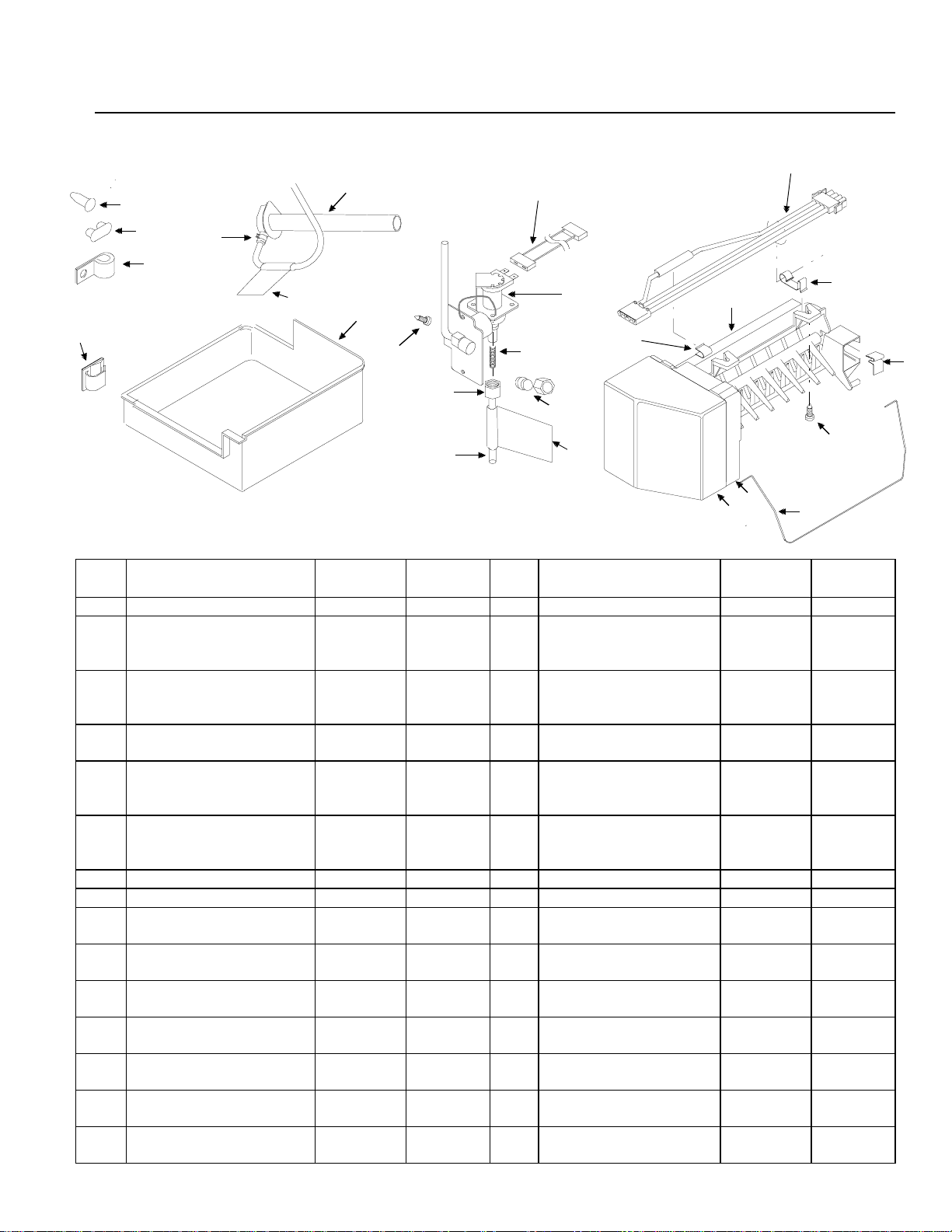
Parts
Use listed part numbers only when ordering replacement parts. Part numbers are not used in installation instructions.
11
5
9
20
6
15
17
14
19
24
12
18
3
13
21
23
16
22
3
1
2
Item Description Part
Number
1 Ice maker D7846305 1 13 Ice storage bucket 10476201 1
2 Ice maker cover 10519801 1 14 Anti-kink spring
N/S Warning label
(attached to side of ice
maker)
N/S Diagnostic label
(inside ice maker cover)
3 Label
(attached to both ends of
plastic tube)
4 16 mm (5/8") long sheet
metal screws (to secure
ice maker)
5 Button plug M0311301 3 18 Plastic clip M0104106 1
6 Oblong plug A3124301 3 19 Water valve 10524607 1
7 Ice maker arm 10884401 1 20 Water valve wire
8 Stainless steel clip B5720302 1 21 9.65 mm
9 Water fill tube elbow 10463201 1 22 6.35 mm (¼") plastic
10 Ice maker wire harness
clamp
11 Ice maker wire harness 10179201 1 N/S Installation Instructions 10527032 1
A3036901 1 N/S Stainless steel insert A3223101 1
10994901 1 15 Hose clamp M0114003 1
10549601 2 16 Compression nut and
M0211018 3 17 “P” clamp M0108105 2
10526701 1 23 Nylon nut and sleeve M0753001 1
Quantity Item Description Part
number
A1055101 1
(inside 6.35 mm O.D.
plastic tube)
10244905 1
sleeve
10525901 1
harness
3
/8") long metal screw
(
tubing
M0251015 1
B5705308 1
10
8
4
7
Quantity
12 Thermal fuse clip
(attached to ice maker)
10319801 1 24 Ice maker shield D7846203 1
N/S 12.7 mm (½") sheet
metal screw
3
M0211017 2
Page 4

!
Procedure
!
1. Turn off water supply to refrigerator .
T o avoid property damage, protect soft vinyl or other
flooring by adjusting leveling legs up, off of floor before
moving refrigerator.
2. Move refrigerator away from wall.
3. Seal open end of copper tubing with masking tape to
keep inside of tubing clean. Route copper tubing up to
refrigerator through floor or interior wall behind
refrigerator providing 9.65 mm (3/8") holes as required.
Copper tubing route must be above 2°C (35°F) to
prevent water line from freezing.
4. Remove vertical cover. Remove and retain lower
vertical cover screws and bottom 2 upper vertical
cover screws on refrigerator cabinet using 6.35 mm
(1/4") hex socket and driver. Remove lower vertical
cover. Retain cover .
5. Remove water valve cover plate. Remove and retain
screws from water valve cover plate using 6.35 mm
(1/4") hex socket and driver. Remove and discard water
valve cover plate.
CAUTION
T o avoid electrical shock which can cause severe
personal injury or death, ground wire must be properly
attached to both bracket and water valve.
6. Connect water valve wires to water valve. Route water
valve wires through rectangular opening. Do not bend
existing opening.
Water val ve
wires
7. Plug wire connector into terminal board. Plug water
valve wire connector into terminal board at points on
top left position, marked 1 and 2 across from A and
stamped on terminal board. Locking finger must snap
in place to secure connection.
WARNING
Water
valve
B
Remove vertical
cover
Metal bottom
cover
Remove water valve
cover plate
Refrigerators with plastic back covers
Remove 2 upper mounting screws using 1/4" hex nut
driver. Create water valve opening by cutting along
perforations and removing cutout. Secure water valve
to mounting plate using 2 original upper mounting
screws.
Water
valve
cutout
Water
valve
mounting
plate
Mounting
screw
Water valve
wire connector
Important
Water valve wire connection can be installed one way .
T erminal board fin prevents improper connector
installation. Do not remove terminal fin.
8. Secure water valve to horizontal bottom cover of
refrigerator. Reinstall original water valve screws using
6.35 mm (1/4") hex nut driver to electrically ground
water valve.
9. Remove tape from end of copper tubing. Put end of
copper tubing into sink or bucket. Partially turn on
water supply to refrigerator. W ater will be under
considerable pressure. Allow water to run through
copper tubing for 1 minute to flush out copper tubing.
Turn off water supply to refrigerator when flushing is
complete.
Terminal
board
4
Page 5

10. Remove plastic cap from water valve tube fitting.
g
g
Connect copper tubing service loop to water valve with
nut and sleeve.
Water fill tube
inlet hole plu
Rear of
refri
DO NOT REMOVE
THIS COVER UNLESS
INSTALLING AN
ICE MAKER
erator
Plastic
cap
1 1. Insert copper tubing completely into water valve inlet
port. Start nut by hand to prevent cross threading.
Firmly connect brass nut on copper tubing to water
valve inlet port fitting using two 12.7 mm (1/2") open
end wrenches. Confirm copper tubing is secure by
pulling on copper tubing. Do not overtighten.
12. Partially turn on water supply to refrigerator and
check for leaks. If leaks are found turn off water
supply to refrigerator and correct any leaks. Repeat
this process until no leaks are found, then completely
turn on water supply to refrigerator.
13. Gently pull ice service rack out of freezer (some
models). Remove screws using a 6.35 mm (1/4") hex
nut driver. Insert provided plugs into screw holes.
14. Remove electrical and water connection cover using
6.35 mm (1/4") hex nut driver to remove screw then
rotate cover upward to remove. Electrical and water
connection cover is located in top left corner of rear
freezer wall. Remove sealing tape from water inlet
tube hole located on interior back freezer wall with
utility knife.
Remove sealing
tape from here
16. Cover end of water fill tube elbow with masking tape to
prevent insulation beads from entering water fill tube
elbow. Push water fill tube elbow through "U"-shaped
hole.
Water fi l l
tube elbow
"U"-shaped
hole
17. Pull water fill tube elbow through hole in freezer . Push
gently on water fill tube elbow while twisting elbow
slightly until elbow is firmly seated inside "U"–shaped
hole in back of refrigerator. Remove masking tape
from end of water fill tube elbow.
18. Remove ice maker from shipping carton and discard
packing material.
Important
Ice maker is shipped with arm down. This is correct
position for ice production. Do not force arm up or
down.
19. Slip stainless steel clip over rear wall of ice maker
water cup.
Stainless
steel clip
Water
cup
15. Remove water tube inlet hole plug on rear of
refrigerator cabinet using a flat blade screwdriver with
masking tape covering blade.
20. Remove and discard 3 button plugs from left freezer
wall using flat blade screwdriver with blade covered
with masking tape.
5
Page 6

!
21. Start 16 mm (5/8") long sheet metal screw in top front
hole using 6.35 mm (1/4") hex socket and driver. Leave
head out approximately 9.65 mm (3/8").
Insert 16 mm (5/8")
sheet metal screw
here
22. Hold ice maker in position. V erify two outside
electrical flats line up with flats in receptacle on
freezer back wall. Insert wire harness plug into
receptacle on rear wall until locking fingers on plug
snap into place. Slip ice maker hanger over sheet
metal screw.
• Locking fingers on plug must be positioned
vertically to mate with wire harness receptacle.
Electrical
connection
Water fill tube
with masking tape
removed
Important
Ice maker can be installed one way only. Do not drill
additional holes.
24. Install two remaining 16 mm (5/8") long sheet metal
screws to secure ice maker. T ighten all 3 screws
Using 6.35 mm (1/4") hex socket and driver.
25. Reinstall freezer shelf.
26. Position ice storage bucket on freezer shelf under ice
maker. Check for leaks at household water
connection and water valve. Correct any leaks.
Carefully tuck wires inside cover to avoid pinching
wires. Reinstall lower vertical cover on rear of
refrigerator cabinet by reversing procedure 4.
27. Create service loop (approximately 2.4 m or 8") using
extreme care to avoid kinks. Secure copper tubing
at back bottom horizontal cover using "P"-clamp,
provided.
Service
loop
Wire harness
plug
Sheet metal
screw
Ice maker
hanger
23. Ease ice maker water cup toward end of water fill
tube. Water fill tube fits under stainless steel clip.
Water fill tube must not be kinked. Water fill tube
elbow should extend approximately 9.65 mm (3/8")
into ice maker water cup and must be secured under
stainless steel clip.
Stainless
steel clip
Water
cup
Wire harness
receptacle
Water fill tube
"P" clamp
CAUTION
T o avoid property damage, all covers must be in place.
28. Plug in refrigerator and move refrigerator in place.
Level if necessary.
29. Check for water leaks 24 hours after installation.
6
Page 7

Operating Instructions
!
Before Calling For Service
• Confirm ice bucket is in place and ice maker arm is
down.
Off
position
Ice maker
arm
On
position
• After freezer section reaches normal temperature, ice
maker fills with water and begins operating. Allow 24–
48 hours after installation before first harvest of ice. Ice
maker produces 7 to 9 harvests of ice in a 24-hour
period under ideal conditions.
• After ice is formed, ice maker drops ice cubes into ice
storage bucket. During ice production, ice maker arm
raises and lowers. When ice storage bucket is full, ice
maker arm turns ice maker off. Discard first 3 harvests
of ice after initially connecting refrigerator to household
water supply and after extended periods of nonuse.
• Stop ice production by lifting ice maker arm. A definite
click is heard when
arm will remain in
pushed down.
off
position is reached. Ice maker
off
position until ice maker arm is
Allow ice maker 1 overnight period to make ice before
assuming a difficulty exists.
If ice maker is not producing ice
• Confirm ice maker arm is down.
• Confirm household water supply is reaching water
valve.
• Confirm ice maker wiring harness is completely
inserted into electrical receptacle.
• Check electrical connections to water valve coil.
• Check for kinks in copper or plastic tubing. Remove
kinks or replace tubing.
• Confirm freezer is operating at proper temperature.
If ice maker is not producing enough ice
• Ice maker produces 7 to 9 harvests of ice in a 24-hour
period under ideal conditions.
• See above section.
If ice maker makes unfamiliar sounds
• These may be normal. Refer to
Sounds
section in Owner's Manual.
Normal Operating
T o avoid damage to ice maker , observe the following:
• Do not force ice maker arm down or up.
• Do not place or store anything on ice maker or in ice
storage bucket.
CAUTION
7
Page 8

Warranty
First Year
Manufacturer will provide a free replacement part, f.o.b. Amana, Iowa, U.S.A., for any part which is defective
due to workmanship or materials.
Ice Maker
Limited One Y ear Warranty
Warranty Limitations
• Begins at date of original purchase.
• Service must be performed by an authorized
Amana technician.
Warranty Is Void If
• Product is used on a commercial, rental or leased
basis.
• Product has defect or damage due to an accident,
fire, flood, connection to an improper electrical or
water supply , lightning, product alteration, shipping
and handling, or other conditions beyond the
control of Amana .
• Product is improperly installed or used.
Owner's Responsibilities
• Provide proof of purchase (sales receipt).
• Provide normal care and maintenance. Replace
owner replaceable items where directions appear
in Owner's Manual and Installation Instructions.
• Make product reasonably accessible for service.
• Pay for premium service costs for service outside
technician's normal business hours.
• Pay for service calls related to product installation
or customer education.
In no event shall Amana Appliances be liable for
incidental or consequential damages
Part No. 10527032
Printed in U.S.A.
1997 Amana Appliances
Amana, Iowa 52204
 Loading...