

Page 1

®
IC55 International
Top and Bottom
Freezer
Refrigerator
Ice Maker Kit
Installation and
Operating
Instructions
Keep these instructions for future reference. Be sure this
manual stays with refrigerator.
Page 2
!
!
Contents
!
Introduction ........................................................................ 2
Safety Instructions .............................................................. 2
Tools Required................................................................... 2
Materials Required ............................................................. 2
Parts ................................................................................... 2
To Begin ............................................................................. 3
Water V alve Installation ...................................................... 3
Installing Ice Maker ............................................................ 4
Connecting Water Supply .................................................. 5
Finishing Up....................................................................... 5
Operating Instructions ........................................................ 6
Before Calling For Service ................................................. 6
Warranty............................................................................. 7
Español .............................................................................. 8
Français............................................................................ 15
Introduction
Read entire manual before installing kit. All necessary
tools and materials must be available prior to installation.
Verify all listed parts are included in kit. If parts are
missing, contact source from whom kit was purchased. If
unable to solve a problem during installation, locate a
Factory service Center or independent authorized
technician by calling 1-800-628-5782 inside U.S.A. and
1-319-622-5511 outside U.S.A. Service is at owner's
expense.
A qualified engineer must connect ice maker in
accordance with these installation instructions. A qualified
engineer must follow local electrical and plumbing
connection regulations.
RECOGNIZE THIS SYMBOL AS A SAFETY
PRECAUTION
Safety Instructions
WARNING
To avoid electrical shock which can cause severe
personal injury or death, unplug power cord or open
household circuit breaker to refrigerator before installing
kit. After installing kit, reconnect power.
CAUTION
To avoid property damage, observe the following:
• REPLACE ORIGINAL ICE STORAGE BUCKET WITH
ONE FROM KIT to avoid spilling ice cubes.
• Confirm water pressure to water valve is
138 Kilopascals
• Start nuts by hand to avoid cross threading. Finish
tightening nuts using a wrench. Do not overtighten.
• Check carefully for water leaks prior to returning
refrigerator to normal location and 24 hours after
connection.
.
Tools Required
Drill with 3/8" drill bit Tape measure
¼" hex nut driver Protective gloves
Adjustable wrench T o we l
Flat blade screwdriver Bucket
Utility knife Masking tape
at least
Materials Required
Important
• Before connecting ice maker , contact a plumber to
connect copper tubing to household plumbing in
6 mm O.D . fle xible copper tubing*.
* Length of copper tubing must reach from water
supply connection plus an additional 2.4 m for
service loop behind refrigerator. Tubing should be
soft instead of rigid and ends should be free of
burrs.
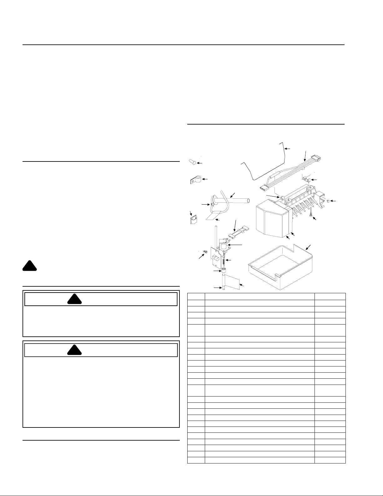
Parts
Use listed part numbers only when ordering replacement
parts. Part number are not used in installation
instructions.
5
15
8
14
16
18
34
19
21
20
Item Description Part #
1
2
N/S
3
4
5
6
7
8
9
10
11
12
13
N/S
14
N/S
15
16
17
18
19
20
21
N/S
Ice maker D7824705
Ice maker cover 10519806
Warning label (attached to side of ice maker) A3036901
Label (attached to both ends of plastic tube) 10549601
16mm long sheet metal screws(secures ice
maker)
Button plug M0311301
Ice maker arm 10884401
Stainless steel clip B5720302
Water fill tube 10463201
Ice maker wire harness clamp 10526701
Ice maker wire harness D7813004
Thermal fuse clip (attached to ice maker) 10319801
Ice storage bucket 10476207
Anti-kink spring (inside 6.4mm O.D. plastic
tube)
Stainless steel insert A3223101
Hose clamp M0114003
Compression nut and sleeve 10244904
“P” clamp M0108105
Plastic clip M0104105
Water valve 10524606
Water valve wire harness 10525901
9.5mm long metal screw M0251015
6.4mm plastic tubing B5705308
Nylon nut and sleeve M0753001
Installation instructions 10527046
13
11
17
3
*N/S signifies 'not shown'.
2
6
10
9
1
2
12
M0211118
A1055101
7
Page 3

To Begin...
!
!
To avoid property damage, protect soft vinyl or other
flooring by adjusting leveling legs up, off of floor before
moving refrigerator.
1. Remove accessories from freezer cabinet
compartment.
All shelves, service racks, and baskets should be
removed. See refrigerator Owner's Manual for details.
2. Locate ice maker connection cover on interior back
freezer wall. Use a ¼" hex nut driver to remove
screws. Rotate cover upward to remove.
3. Insert screwdriver into inlet tube hole
sealing tape
4 Position unit to allow access to back side.
5. Locate water fill tube from ice maker kit. Inspect
inside of tube for dirt or other foreign substances.
Clean if necessary . Co ver end of tube with masking
tape to block substances from entering tube during
install.
6. Locate water inlet plug on back of unit (Lower right
hand corner on bottom mount freezer units. Upper
right hand corner for top mount freezer units.).
Remove with flat blade screwdriver with masking tape
covering blade.
7. Push water fill tube elbow
hole
(B)
(B)
.
CAUTION
.
B
(A)
to pierce
A
(A)
through "U"-shaped
Bottom Freezer Models
Remove and retain vertical cover(A) on refrigerator
cabinet using ¼" hex nut driver. Retain screws f or
water valve install.
A
2. Remove water valve cover plate(B).
Refrigerators with fiberboard back bottom cover
Create water valve opening
perforations in fiberboard cover
Remove fiberboard.
B
Refrigerators with metal back bottom cover(B)
Remove and retain screws from water valve cover
plate(A) using ¼" hex socket and driv er .
A
(B)
by cutting along
(A)
using utility knife.
A
B
A
B
WARNI NG
To avoid electrical shock which can cause severe
personal injury or death, ground wire must be properly
attached to both bracket and water valve.
3. Connect water valve harness(B) to water valve(A).
Water Valve Installation
Note: For install of water valve for 91 cm wide cabinet
models(built-in designs), see section entitled
91 cm Wide Bottom Freezer Cabinet Width
Models.
1. Remove v ertical cover
T op Freezer Models
Remove and retain low er vertical cover screws and
bottom 2 upper vertical cover screws on refrigerator
cabinet using ¼" hex sock et and driver. Remove
lower vertical cover.
(A)
.
For
Thread water valve harness through cover plate
opening. Do not bend existing opening.
C
B
A
3
Page 4

4. Plug water valve harness(B) into terminal board(A)* at
points on position, marked 1 and
B
stamped on terminal board. Locking finger must
2
across from A and
snap in place to secure connection.
* Ter minal design may vary. Follow markings on board for
correct install.
harness from refrigerator into assembly .
• Insert harness(B) and valve through opening in back
cover. Mount valve to bac k co v er(C) with hex head
screws retained from cover plate removal.
Thread water valve wires through rectangular
opening. Do not bend existing opening.
A
B
5. Secure water valve to bottom rail
(A)
of refrigerator*.
Reinstall original water valve screws using ¼" hex
nut driver to electrically ground water valve.
* Some models may contain a mounting plate
area. If present, remove with a ¼" hex nut driver and
discard.
(B)
A
B
Refrigerators with metal back bottom cover
6. Replace bottom metal cover
in this
B
A
C
Installing Ice Maker
1. Pull water fill tube elbow through hole in freez er.
Remove masking tape from end of water fill tube
elbow. Push gently on w ater fill tube elbow while
twisting elbow slightly until elbow is firmly seated
inside "U" shaped hole in back of refrigerator .
2. Remove ice mak er from shipping carton and discard
packing material.
Important: Ice maker is shipped with arm down. This
is correct position for ice production. Do not force arm
up or down.
3. Slip stainless steel clip
water cup
(B)
.
(A)
over rear wall of ice maker
For 91 cm Wide Bottom Freezer Cabinet Models
1. Remove and retain screws from water valve cover
plate(A) using ¼" hex socket and driv er .
A
• Remove wire harness attached to cover plate by
squeezing wire tie(A) with pliers and pushing tie
through hole in plate. Pull end of wire harness
through opening in back cover . Discard plate .
A
• Locate water valve assembly(A) in ice maker kit.
Remove harness from assembly and discard. Plug
A
B
4. Start 16mm long sheet metal screw in top front and
top rear holes
(A)
in freezer wall* using ¼" hex socket
and driver. Lea ve heads out appro ximately 9.53 mm.
* Some models may have plugs or screws mounted in
freezer wall. Remove with appropriate tool before
proceeding to next step.
A
5. Hold ice maker in position. Verify two outside electrical
flats line up with flats in receptacle on freezer back
4
Page 5

Connecting Water Supply
wall. Insert wire harness plug
on rear wall until locking fingers on plug snap
into place. Slip ice maker hanger
metal screw
Bottom freezer models electrical connection
• Locking fingers on plug
horizontally to mate with wire harness
receptacle
(D)
(B)
.
.
A
(A)
into receptacle
(C)
over sheet
(A)
must be positioned
B
D
C
T op freezer models electrical connection
• Locking fingers on plug
vertically to mate with wire harness receptacle
A
(A)
must be positioned
B
D
C
(B)
(B)
Important
• When routing copper tubing to refrigerator through
floor or interior wall, holes must be 10 mm in diameter.
T ape end to protect against entry of f oreign
substance.
• Copper tubing route must be above 2°C to prevent
water line from freezing.
1. Remove tape from end of copper tubing. Put end of
copper tubing into sink or buck et. P artially turn on
water supply to refrigerator. Water will be under
considerable pressure. Allow water to run through
copper tubing for 1 minute to flush out copper tubing.
T urn off water supply to refrigerator when flushing is
complete.
2. Remove plastic cap(A) from water valve tube fitting.
Connect copper tubing to water valve with nut and
sleeve.
.
B
A
6. Ease ice maker water cup
tube
(B)
. W ater fill tube fits under stainless steel
clip
(C)
. W ater fill tube must not be kink ed. W ater fill
tube should extend approximately 9.5 mm into ice
maker water cup and must be secured under
stainless steel clip.
C
(A)
toward end of water fill
B
A
7. Install remaining 16mm long sheet metal screw to
secure ice maker. Tighten all 3 screws using ¼" he x
socket and driver.
8. Reinstall freezer accessories. See owner's manual
for proper instruction.
9. Locate ice storage bucket in ice maker kit. Position
bucket under ice mak er .
3. Insert copper tubing completely into water valve inlet
port(B). Start nut by hand to pre vent cross threading.
Firmly connect brass nut on to water valve inlet port
using two ½" open end wrenches. Confirm copper
tubing is secure by pulling on copper tubing. Do not
overtighten.
4. Partially turn on water supply to refrigerator and check
for leaks. Turn off w ater supply to refrigerator a n d
correct any leaks.
5. Reinstall vertical cover on refrigerator cabinet
6. Create service loop(A)of approximately 2.4 m using
extreme care to avoid kinks. Secure copper tubing
at back bottom horizontal cover using "P"clamp(B), provided.
A
B
5
Page 6

CAUTION
!
!
To avoid property damage, all covers must be in
place.
Finishing Up
1. Plug in refrigerator and move refrigerator in place.
Level if necessary.
2. Check for water leaks 24 hours after installation.
Operating Instructions
• Be sure you have REPLACED ORIGINAL ICE
STORAGE B UCKET WITH ONE FROM KIT to a void
spilling ice cubes.
• Confirm ice bucket is in place and ice maker arm
down for operation
position
(C)
.
(B)
. Raise arm for the
off
C
A
(A)
Before Calling For Service
Allow ice maker 1 overnight period to make ice before
assuming a difficulty exists.
If ice maker is not producing ice
• Confirm ice maker arm is down.
• Confirm household water supply is reaching water
valve. Ice maker requires a pressure of 20–100 psi to
function properly .
• Confirm ice maker wiring harness is completely
inserted into electrical receptacle.
• Check electrical connections to water valve coil.
• Check for kinks in copper or plastic tubing. Remove
kinks or replace tubing.
• Confirm freezer is operating at proper temperature.
If ice maker is not producing enough ice
• Ice maker produces 7–9 harvests of ice in a 24-hour
is
period under ideal conditions.
• See above section.
If water supply is leaking
• Partially turn on water supply to refrigerator and check
for leaks. Turn off water to refrigerator and correct
leak. Repeat process until leaks are gone.
If ice maker makes unfamiliar sounds
• These may be normal. Refer to
Sounds
section in Owner's Manual.
Normal Operating
B
• After freezer section reaches normal temperature, ice
maker fills with water and begins operating. Allow 24 to
48 hours after installation before first harvest of ice.
Ice maker produces 7–9 harvests of ice in a 24-hour
period under ideal conditions.
• After ice is formed, ice maker drops ice cubes into
ice storage bucket. During ice production, ice maker
arm raises and lowers. When ice stor age buc ket is full,
ice maker arm turns ice maker off. Discard first 3
harvests of ice after initially connecting refrigerator to
household water supply and after extended periods of
non-use.
• Stop ice production by lifting ice maker arm. Adefinite
click is heard when
will remain off until ice maker arm is pushed down.
off
position is reached. Ice maker
CAUTION
To avoid damage to ice maker , observe the follo wing:
• Do not force ice maker arm down or up.
• Do not place or store anything on ice maker or in
ice storage bucket.
6
Page 7

Warranty
First Year
Amana Appliances will provide a free replacement part, f.o.b . Amana, Iowa, U.S.A., f or any part which is
defective due to workmanship or materials.
Ice Maker
Limited One Year W arranty
Warranty Limitations
• Begins at date of original purchase.
• Service must be performed by an authorized
Amana technician.
Warranty Is Void If
• Product is used on a commercial, rental or leased
basis.
• Product has defect or damage due to an accident,
fire, flood, connection to an improper electrical or
water supply , lightning, product alteration, shipping
and handling, or other conditions beyond the
control of Amana .
• Product is improperly installed or used.
Any questions regarding the above or to locate an authorized servicer , contact appliance supplier, or:
Owner's Responsibilities
• Provide proof of purchase (sales receipt).
• Provide normal care and maintenance. Replace
owner replaceable items where directions appear
in Owner's Manual and Installation Instructions.
• Make product reasonably accessible for service.
• Pay for premium service costs for service outside
technician's normal business hours.
• P a y f or service calls related to product installation
or customer education.
In no event shall Amana Appliances be liable for
incidental or consequential damages
International Division
Amana
2800 220th Trail
PO Box 8901
Amana, IA 52204-0001
USA
T elephone 1-319-622-5511
Facsimilie 1-319-622-8595
7
Page 8

10527050 © Amana Appliances
www.amana.com
Printed in U.S.A. - 11/99
 Loading...