


®
Gas
Self-Clean
Owner's
Downdraft
an
anual
AG
* Additional alphanumeric characters representing
other models in series may follow each model
number,
Natural Gas Only
Please Read Manual Before installing and
Operating Range
e
important
Save for local electrical inspector's use.
installer
Leave this manual and other literature with consumer for
future use.
Customer
Keep these instructions for future reference. If appliance
changes ownership, be sure this manual accompanies
range.

Contents
Model Identification ................................................. 2
Parts and Accessories ............................................ 2
Service .................................................................... 2
Asure TM Extended Service Plan .............................. 2
Important Safety Information ....................................... 3
Installation .................................................................. 6
Packing Material ..................................................... 6
Cabinet Opening ..................................................... 6
Minimum Clearances to Combustible Surfaces ....... 7
Installing Side Trim ................................................. 7
Electrical Connection Requirements ....................... 8
Electrical Connection Clearance ............................. 8
Gas Supply Location ............................................... 8
Gas Supply Pressure .............................................. 9
Duct Requirements ................................................. 9
Duct Location ......................................................... 9
Duct Length ............................................................ 10
Duct Connection ..................................................... 12
Gas Connection Requirements ................................ 13
Pressure Regulator Location ................................... 13
Gas Connection ...................................................... 13
Testing for Gas Leaks ............................................. t4
Seal Openings ........................................................ 14
Anti-tip Bracket Installation ..................................... 14
Place and Level Range ............................................ 15
Removal and Replacement of Range ....................... 15
Test and Adjust Oven Burner Flame ........................ 15
Cartridges .................................................................. 16
Cartridge Features .................................................. 16
Installing Cartridges ................................................ 16
Removing Cartridges ............................................... 18
Adjusting Surface Burner Low Flame Size .............. 18
Testing and Adjusting Burner Flame Characteristics 19
Igniting Surface Burner without Electricity ............... 19
Features .................................................................... 20
Operation ................................................................... 23
Setting Clock .......................................................... 23
Setting Minute Timer ............................................... 23
Prepare to Bake ...................................................... 23
Baking .................................................................... 24
Timed Baking .......................................................... 24
Delayed Baking ....................................................... 25
Adjusting Oven Temperature .................................... 25
Broiling ................................................................... 25
Prepare for Self-clean and
Delayed Self-clean Cycle ........................................ 26
Self=cleaning ........................................................... 26
Delayed Self=clean Cycle ........................................ 26
Operating Surface Burners ...................................... 27
Cooking Utensils ..................................................... 28
Smoke Control Grill TM and Griddle .......................... 29
Cooking Guide ........................................................... 30
Care and Cleaning ...................................................... 32
Removing Oven Door ............................................... 32
Replacing Oven Light .............................................. 32
Removing Storage Drawer ....................................... 33
Removing Vent Filter ............................................... 33
Cleaning .................................................................. 34
BEFORE CALLING FOR SERVICE ............................ 36
VVarranty .................................................................... 37
Quick Reference Instructions ..................................... 38
Model Identification
Complete enclosed registration card and promptly return.
If registration card is missing, call Consumer Affairs
Department at 1-800-843-0304 inside U.S.A.
319-622-55tl outside U.S.A. When contacting Amana,
provide product information located on rating plate. Rating
plate is located on the oven frame. Record the following:
Model Number:
Manufacturing Number:
Serial or S/N Number:
Date of purchase:
Dealer's name and address:
Save Time and Money
If something seems unusual
PLEASE CHECK BEFORE CALLING
FOR SERVICE page 36,
Parts and Accessories
Purchase replacement parts and additional accessories
(e.g., refrigerator shelves, dryer racks, or cooktop
modules) over the phone. To order accessories for your
Amana product, call 1=800-843=0304 inside U.S.A. or
319=622=5511 outside U.S.A.
Service
Keep a copy of sales receipt for future reference or in
case warranty service is required. Any questions or to
locate an authorized servicer, call 1-800-NAT=LSVC
(1-800=628-5782) inside U.S.A. 319-622-5511 outside
U.S.A. Warranty service must be performed by an
authorized servicer. Amana Appliances also recommends
contacting an authorized servicer if service is required
after warranty expires.
Asure TM Extended Service Plan
Amana offers long=term service protection for this new
range. Asure TM Extended Service Plan is specially
designed to supplement Amana's strong warranty.
This plan covers functional parts, labor, and travel
charges. Call 1=800=528=2682for information.
2

iMPORTANT SAFETY iNFORMATiON
WARNING
To reduce the risk of the appliance tipping, it must be
secured by a properly installedanti-tip bracket. To
make sure bracket has been installedproperly, remove
the storage drawer or panel and look under the range
with a flashlight. Bracket must be engaged in the rear
corner of the range.
,, ALL RANGES CAN TIP
,, INJURY TO PERSONS
COULD RESULT
,, INSTALL ANTI-TIP
BRACKET PACKED
WITH RANGE
,, SEE INSTALLATION
INSTRUCTIONS
WARNING I
To avoid death, personal injury or property damage,
information in this manual must be followed exactly.
- Do not store or use gasoline or other flammable
vapors and liquids in the vicinity of this or any other
appliance.
- WHATTO DO IFYOU SMELL GAS
Do not try to light any appliance.
Do not touch any electrical switch; do not use
any phone in your building.
Immediately call your gas supplier from a
neighbor's phone. Follow the gas supplier's
instructions.
If you cannot reach your gas supplier, call the fire
department.
Installation and service must be performed by a
qualified installer, service agency or the gas
supplier.
WARNING
To avoid personal injury or property damage from
smoke or fire, do not store combustible gasoline or
other combustible materials near range.
WARNING
To avoid risk of electrical shock, personal injury, or
death, make sure your range has been properly
grounded and always disconnect it from main power
supply before servicing.
WARNING
To avoid personal injuryor property damage from
smoke or fire, do not use grill or griddle iffan is not
operating. In the unlikely event that the fan is not
operating, contact an authorized service technician.
CAUTION
DO NOTTOUCH AREAS NEAR SURFACE
BURNERS--Areas near surface burners may become
hot enough to cause burns. During and after use, do
not touch, or let clothing touch or other flammable
materials contact surface burners or areas near
surface units until they have had enough time to cool.
These areas include the rangetop and backguard.
CAUTION
DO NOTTOUCH INTERIOR SURFACES OF OVEN--
Interior surfaces of an oven may become hot enough
to cause burns. During and after use, do not touch, or
let clothing or other flammable materials touch heating
interior surfaces of oven until they have had enough
time to cool. Other range surfaces that may become
hot enough to cause burns are the oven door and oven
vent under range backguard.
WARNING !
To avoid personal injury, do not sit, stand or lean on
oven door or oven drawer.
WARNING !
Gas leaks may occur in your system and result in a
dangerous situation. Gas leaks may not be detected by
smell alone. Gas suppliers recommend you purchase
and install an UL approved gas detector. Install and
use in accordance with manufacturer's instructions.

CAUTION l
This appliance contains or produces a chemical or
chemicals which can cause death or serious illness
and which are known to the state of California to
cause cancer, birth defects or other reproductive harm.
To reduce the risk from substances in the fuel or from
fuel combustion make sure this appliance is installed,
operated, and maintained according to the instructions
in this booklet.
CAUTION
Do not store items of interest to children in cabinets
above a range or behind the backguard of a range.
Children climbing on the range to reach items could
be seriously injured.
CAUTION 1
To avoid delayed or improper ignition, do not obstruct
the flow of combustion or ventilation air.
ALL APPLIANCES
1. Proper installation. Be sure your appliance is properly
installed and grounded by a qualified technician.
2. Never Use Your Appliance for Warming or Heating the
Room.
3. Do not leave children alone. Children should not be
alone or unattended in the area where the appliance
is in use. They should never be allowed to sit or stand
on any part of the appliance.
4. Wear proper apparel. Loose fitting or hanging
garments should never be worn while using appliance.
5. User Servicing--Do not repair or replace any part of
the appliance unless specifically recommended in the
manual. All other servicing should be referred to a
qualified technician.
6. Storage in oron appliance. Flammable materials
should not be stored in an oven or near surface units.
7. Do not use water on grease fires. Smother fire or
flame, or use dry chemical or foam-type extinguisher.
8. Use only dry potholders. Moist or damp potholders on
hot surfaces may result in burns from steam. Do not
let potholder touch flame. Do not use a towel or other
bulky cloth.
SURFACE COOKING UNITS
1. Use proper pan size. This appliance is equipped with
one or more surface units of different size. Select
utensils having flat bottoms large enough to cover the
surface unit heating element. The use of undersized
utensils will expose a portion of the burner to direct
contact and may result in ignition of clothing. Use of
oversized utensils concentrates heat on cooking
surface and can cause damage to range. Proper
relationship of utensil to burner improves efficiency.
2. Never leave surface units unattended. Boilover causes
smoking and greasy spillovers that may ignite.
3. Make sure drip bowls are in place. Absence of these
pans or bowls during cooking may subject wiring or
components underneath to damage.
4. Protective liners. Do not use aluminum foil to line drip
bowls or oven bottom. Improper installation of these
liners may result in a risk of fire.
5. Glazed cooking utensils--Only certain types of glass,
ceramic, earthware, or other glazed utensils are
suitable for rangetop service without breaking due to
sudden change in temperature.
6. Utensil handles should be turned inward and not
extend over adjacent surface units. To reduce the risk
of burns, ignition of flammable materials, and spillage
due to unintentional contact with the utensil, the
handle of a utensil should be positioned so that it is
turned inward, and does not extend over adjacent
surface units.
OVENS
1. Use care when opening door. Let hot air or steam
escape before removing or replacing food.
2. Do not heat unopened food containers. Build-up of
pressure may cause container to burst and result in
injury.
3. Keep oven vent ducts unobstructed.
4. Placement of oven racks. Always place oven racks in
desired location while oven is cool. If rack is removed
while oven is hot, do not let potholder contact burner
inoven.
SELF=CLEANING OVENS
1. Do not clean door gasket. The door gasket is
essential for a good seal. Care should be taken not
to rub, damage, or move the gasket.
2. Do not use oven cleaners. No commercial oven
cleaner or oven liner protective coating of any kind
should be used in or around any part of the liner.
3. Clean only parts listed in manual.
4. Before self-cleaning the oven, remove broiler pan,
oven racks, and other utensils.
5. Remove all items from rangetop and backguard.
4

VENTiLATiON DUCTS
1. Clean ventilation ducts frequently. Grease should not
be allowed to accumulate on hood or filter.
2. When flaming foods, turn fan on.
in Case of Fire
Fires can occur as a result of over cooking or excessive
grease. Though a fire is unlikely, if one occurs, proceed
as follows:
Surface Element Fire
1. Smother the fire with a nonflammable lid or baking
soda, or use a Class ABC or BC extinguisher. Not
water. Not salt. Not flour.
2. As soon as it is safe to do so, turn the surface
controls to OFF. Turn off power at main circuit breaker
or fuse box, and gas supply.
Oven Fires
1. Ifyou see smoke from your oven, do not open oven.
2. Press OVEN CANCEL pad to tum off oven.
3. As an added precaution, turn off power at main circuit
breaker or fuse box, and gas supply.
4. Turn on vent to remove smoke.
5. Allow food or grease to burn itself out in oven.
6. If smoke and fire persist, call fire department.
7. If there is any damage to components, call an
authorized servicer before using range.
Delayed ignition
Surface Burners
Burner should ignite within 4 seconds. If burner does not
ignite within 4 seconds turn control knob to OFF position
and follow directions for installing burner caps "Installing
Cartridges" section. Try burner again. If burner still does
not ignite in 4 seconds, contact an authorized servicer.
Bake and Broil Burner Flame
Allow no more than 40-60 seconds before burner ignites
and heat is felt. To check for heat, open oven door to first
stop and place hand over oven door. If heat is not felt,
press OVEN CANCEL pad to turn offoven. If burner
repeatedly fails to ignite, contact an authorized servicer.
Precautions
• Do not cook food directly on rangetop surface, always
use cookware.
• Do not mix household cleaning products. Chemical
mixtures may interact with objectionable or even
hazardous results.
• Do not put plastic items on warm cooking areas. They
may melt and stick.
• Do not slide rough metal objects across rangetop
surface. Scratching or metal marking can result.
• Do not leave fat heating unless you remain nearby. Fat
can ignite if overheated by spilling onto hot surfaces.
• Do not allow pots to boil dry as this can cause damage
to cooking surface and pan.
• Do not use rangetop surface as a cutting board.
• Do not use range for storage or as adisplay counter.

Installation
Packing Material
Remove protective packing materials from range. Tape
residue can be cleaned with a soft cloth and alcohol.
Duct pieces are in range storage drawer and oven cavity.
Remove all protective plastic and any residue on stainless
steel models. Any left on unit may cause spotting.
Cabinet Opening
Using dimensions, prepare cabinet opening.
Range extends beyond cabinet when installed.
WARNING
To avoid risk of burns or fire by reaching over surface
burners, cabinet storage space located above range
should be avoided. Ifcabinet storage isprovided,
install a range hood that projects horizontally a
minimum of 5 inches beyond the cabinet bottom to
reduce the risk.
E
A_30I/s to 30 inches
B--36 inches standard
C--35 inches standard
D_24 inches standard
E 25 inches standard
A--13/4 inches minimum
B--36 inches standard
C--35 inches standard
D--24 inches standard
E--30I/8 to 30 inches
F_25 inches standard
Standard Cabinet and Countertop with Backsplash
Standard Cabinet and Countertop without Backsplash
F
B
A_301/8 to 30 inches
B--36 inches standard
C--35 inches standard
D_24 inches standard
E 23_/2inches
F 25 inches minimum
Standard Cabinet and Countertop in island

Minimum Clearances to Combustible
Surfaces
Using dimensions, prepare cabinet opening.
• Minimum clearance to rearwall is 0 inches.
• Minimum clearance to a vertical right or left side wall is
3 inches.
• Minimum clearance to countertop/cabinet on each side
is 0 inches.
• Minimum of 30 inches between top of cooking surface
and bottom of an unprotected wood or metal cabinet.
• Minimum of 24 inches between cooking surface and
protected wood or metal cabinet above range. Cabinet
bottom must be protected by at least ¼ inch thick
millboard with not less than No. 28 MSG sheet steel,
.015 inch thick stainless steel, .024 inch thick
aluminum, or .020 inch thick copper.
Installing Side Trim
If desired, optional side trim provided can be installed on
range. Side trim must be installed above counter top level and
tapped down into place.
Side trim can be mounted in several different positions
depending on counter top opening, cabinet structure, and
range features.
Freestanding with Backsplash
To mount trim flush with front of counter top, use #3 trim
holes and "A" range holes. Trim does not extend the full
length of the cooking surface.
Optional Mounting
"A" range holes allow an extra 3/8-inchforward
adjustment. Trim holes #1, #2, and #3 allow a 72-inch
adjustment. Trim can be mounted in any desired location
using holes provided.
E
_30 inches minimum
B 30 inches unprotected/24 inches protected minimum
C 13inches maximum
D 3 inches minimum (Both Sides)
E 18 inches minimum
Minimum Clearances to Combustible Surfaces
Side of Range
Side Trim
Side Trim
A
23
2
2
3.
Left
A If the countertop is roll formed, notch the countertop to allow
for overlapping trim.
B Side trim
Roll Formed Countertop

Electrical Connection Requirements
WARNING 1
To avoid the risk of serious electrical shock or property
damage, do not cut or remove the third (ground) prong
from the power plug. A 3-wire grounded conductor
system must be used. Relying on the flexible
connector, hard piping or any other part of the gas
supply line as a ground may cause fire, electrical
shock and/or erratic control operation.
Electrical Connection Clearance
Electrical connection must be located in the shaded area
shown. Electrical connection must not interfere with gas
connection.
Range must be electrically grounded in accordance with
local codes or in the absence of local codes, with the
National Electrical Code, ANSI/NFPA No. 70-Latest
Edition.
In Canada, electrical connections are to made in
accordance with CSA C22.1 Canadian Electrical Code.
All electrical connections are to be made in accordance
with CSA standards Z240.6.1 electrical requirements for
mobile homes.
Use a dedicated 120 volt, 60 hertz, 3-prong receptacle
protected by a 15 amp circuit breaker or time delay fuse.
A qualified electrician should confirm the outlet is properly
grounded and polarized.
If a 2-prong outlet is encountered, range owner must
replace outlet before using range. Do not cut off cord, use
plug adapter or extension cord, or remove grounding plug.
L1 Neutral
Neutral
side 115 ± 1:
C
_18 inches (45,2 cm)
B_0 inches (50,8 cm)
C 5 inches (12,7 cm)
D 10inches (25,4cm)
_301/4 inches(76,5cm)
Electrical Connection Location
C
Gas Supply Location
Gas supply must be located in the shaded area shown.
Gas connection must not interfere with the electrical
connection.
prong
Standard 120 Volt, 60 Hertz
\
A_4 inches (10,2 cm)
B 2inches (5 cm)
C 2inches (5 cm)
Gas Supply Location

Gas Supply Pressure
1 CAUTION
To avoid property damage, maximum gas supply
pressure must not exceed 14" WCP.
• Appliance and individual shutoff valve must be
disconnected from the gas supply piping system during
any pressure testing of that system at test pressures in
excess of ½ psig (3.5kPa) (14" WCP).
• Appliance must be isolated from gas supply piping
system by closing manual shutoffvalve during any
pressure testing of the gas supply piping system at
test pressures equal to or less than ½ psig (3.5kPa)
(14" WCP).
• Gas supply pressure for checking regulator setting
must be at least 1"WCP above manifold pressure
shown on rating label.
Duct Requirements
• Duct should be 6-inch round metal ducting. Island or
peninsula installations may require 31/4X 10 inch duct.
• To ensure proper ventilation, duct work must not exceed
60 equivalent feet.
• Curved fittings should not account for more than 50% of
duct length.
• Flexible duct is not recommended because of irregular
interior surface. Ifflexible duct is to be used, one foot is
equal to 2 feet of metal duct. NEVER USE PLASTIC
TYPE DRYER DUCTING.
• Do not vent into an attic or crawl space. Vent range
outside.
• Flexible duct elbows are equal to twice as many feet as
smooth metal elbows.
• Never install two elbow fittings next to each other. Two
elbows installed together create a poor vent path and
insufficient ventilation.
• Seal all duct joints tightly using duct tape. Openings left
in ducting allow smoke and odor to escape inside
house.
• For best performance, do not use more than three 90°
elbows.
• 6-inch transition duct provided must be mechanically
secured to exhaust blower outlet. Secure transition duct
using two screws provided.
Duct Location
Backwall
1. Locate studs inwall.
2. Measure and cut an opening for thimble as illustrated
in figure below. Cutout should be 6%-inch diameter
circle.
3. Ducting is completed in Duct Connection section.
q
C_
_8 inches
B 45/16inches
Backwall Duct Location

Floor
1. Locate studs in floor.
2. Measure to locate center of floor duct location. See
figure below.
3. Cut anopening for floor transition piece as illustrated
in figure below. Cutout should be 71/4x 71/4inches
square. If opening is not correctly aligned, duct does
not connect properly.
4. Ducting is completed in Duct Connection section.
Duct Length
Ducting design is in terms of maximum length of straight
metal duct. To ensure proper air movement, limit fittings,
other than straight, to 50% of total duct length. Maximum
allowable calculated duct length is 60 equivalent feet.
• Use Duct Length Piece Equivalents section to calculate
duct length.
• Flexible duct is not recommended because it can
create a fire hazard. However, if it is used, one foot of
flexible duct is equal to two feet of smooth metal duct.
C
A
_107/s inches
B 131/sinches for installation with counter top or backsplash
behind range. 11% inches for installation without counter top
or backsplash behind range.
Floor Duct Location
Transition
Piece 0'
90° Elbow 5'
10' of Duct 10'
Wall Cap 0'
Total Feet 15'
Duct Length Example
10

Duct Length Piece Equivalents
1 foot of 31¼x 10 inch duct = 1 equivalent foot
I
1 foot of 6 inch pipe = 1 equivalent foot
31/4x 10 inch to 6 inch
transition = 4½ equivalent
feet
31/4x 10 inch to 6 inch 90
degree transition =
5 equivalent feet
31Ax 10 inch 90 degree
elbow = 5 equivalent feet
31/4x 10 inch flat elbow =
12 equivalent feet
6 inch to 31/4x 10 inch
transition =
1 equivalent foot
6 inch to 31/4x 10 inch 90
degree transition =
5 equivalent feet
6 inch 90 degree elbow =
5 equivalent feet
6 inch 45 degree elbow =
2½ equivalent feet
31/4x 10 inch wall cap
(Unrestricted) =
0 equivalent feet
6 inch wall cap
(Unrestricted) =
0 equivalent feet
11

Duct Connection
Floor
1. Attach rubber gasket around edge of transition piece.
• Flat side of rubber gasket must be on under side of
transition piece, See figure below,
A
%
%
A Transition piece
B Gasket
.
Remove blower transition from blower.
5.
Attach floor elbow duct to blower using 2 screws
provided.
• Floor elbow duct should be inside blower.
.
Connect electrical supply.
7.
Push range into position.
• Tilt range slightly while pushing in range. Tilting
range allows floor plate to clear gasket.
• Make sure that floor elbow duct is directly over
transition piece and rubber gasket.
• Rubber gasket provides a seal between floor elbow
and transition piece.
Backwall
1. Remove screw in front of blower transition separating
blower transition from blower housing.
2. Place hose clamp around round end of blower
transition and attach flex duct to blower transition
using hose clamp.
Floor Connection
.
Place round end of transition piece into floor. Secure
transition piece using 8 screws provided in kit.
• Lift edge of rubber gasket to install screws.
• Make sure round edge of gasket isfacing up.
.
Insert floor plate into elbow duct and attach using 2
screws provided.
• Tighten only front screw.
• When installed, wide flange of floor plate must face
toward back of range.
A \
\ B
I
_Blower
B Floor elbow duct
C_loor plate
D_ransition piece and gasket
E_lower transition
A \
• \
D
A Blower and transition piece
B_ose clamps
_Flex duct
D Thimble
Baclcwall Connection
3. Place long end of thimble into wall and secure
thimble using four screws provided, one in each
corner.
4. Place hose clamp provided around short end of
thimble. Attach opposite end of flex duct to short
end of thimble using hose clamp.
5. Connect electrical supply.
6. Carefully push range back into position. Avoid
pinching transition piece or flex duct.
Insert Floor Plate into Elbow Duct and Attach
12

7. Usingguidescrewtolocateholeinrearofblower
housingpositiontransitioninsideblowerhousing.
Rotatetransitionuntilholeinfrontofblowerhousing
isaligned.Securetransitionwithscrewprovided.
8. Sealallductjointswithducttape.
9. Checkunderrangetobesurelevelinglegisfully
engaged in the anti-tip bracket.
10. Instafl storage drawer.
Gas Connection Requirements
Before connecting this appliance to the gas supply piping
system, confirm installationmeets the requirements of local
codes, or in the absence of local codes, with the National
Fuel Gas Code, ANSi Z223.1 -Latest Edition.
Gas Connection (Natural Gas Only)
Connect gas supply to regulator using hard pipe or flexible
connector (Check local codes). Pressure regulator
supplied with this appliance has al/2 inch NPT female
connection. If gas union is used, remove storage drawer,
slide range into place, and connect union.
® A manuN shutoff, not supplied with range, must be
installed in an accessible location outside of range.
® Use joint compound on all male pipe threads.
® Use supplied pressure regulator only.
® Do not overtighten gas fitting when attaching to
pressure regulator. Overtightening may crack regulator.
® Support pressure regulator with wrench when instNling
gas fitting.
When installed in mobile housing, installation is to be in
accordance with CSA standard Z241.1 gas equipped
mobile housing.
The installation of appliances designed for manufactured
(mobile) home installation must conform with
Manufactured Home Construction and Safety Standard,
Title 24 CFR, Part 3280, or when such standard is not
applicable, the Standard for Manufactured Home
Instaflation, ANSI225.1/NFPA 501 A-Latest Edition, or with
local codes or the standard CAN/CSA-z240MH, "Mobile
Homes", and with local codes where applicable.
The instNlation of appliances is to be in accordance with
CAN1 =B149.1 or B149.2 installation code for gas burning
appliances and equipment and/or local codes. Part 1 and/
or local codes.
Pressure Regulator Location
Remove the storage drawer and locate regulator under
oven cavit'r inrear.
,/
1
WARNING !
To avoid property damage or personal injury, only use
a new flexible connector that is AGA/CGA design
certified.
• Do not use an old connector.
• Do not reuse a connector after moving appliance.
A B
A Regulator
B_Flexibte Connector
C_Manual Shut Off Valve
D_Adaptor
Flexible Connection
Pressure Regulator Location
insure red tab
REMAINS in the
OPEN or On
position during
installation.
13

A B C
F
_Union
B_anual Shut OffValve
C_educing Elbow (3/4-inch to l/2-inch)
D 3/4-inch Stub
E 1/2-inch Nipple
F Regulator
Hardpipe Connection
Testing for Gas Leaks
Leak Testing of the appliance shall be conducted
according to the manuafacturer's instructions. After final
gas connection is made, turn on manual gas valve and
test all connections in gas supply piping and range for
gas leaks,
E
WARNING
Seal Openings
Openings in wall behind the range or on floor under range
must be sealed before sliding range into position.
Anti=tip Bracket Installation
To reduce risk of range tipping, secure range with a
properly installed anti-tip bracket.
1. Measure (A)from back wall on right and left side of
cabinet cutout. Mark measurements on floor and draw
a straight line connecting marks.
• Measure 31/2inches when installed with
backsplash.
• Measure 13/4inches when installed without
backsplash.
• Drop vertical line from back of cutout and measure
1_/2inches when installed in island.
2. Position anti-tip bracket.
• If range is installed beside cabinet(s), place anti-tip
bracket with back edge on line drawn on floor and
side of bracket against cabinet.
• If range is not installed beside cabinet(s), position
range where it will be installed. Draw a line along
side of range on floor from front to back. Remove
range. Place anti-tip bracket with back edge over
line drawn from back wall and side of bracket over
line drawn along side of range on floor.
• Anti-tip bracket can be installed on either right or
left side.
Toavoid property damage or serious personal injury,
never use a lighted match to test for gas leaks.
Place soap suds on connection.
• Bubbles appear if leak is present.
2. Ifbubbles appear, shut off gas supply valve.
3. Tighten joint if leak is at factory fitting.
• If leak is not at factory fitting, unscrew, apply more
joint compound, and tighten to correct leak.
4. Retest connection for leak after tightening.
• Retest any connections that were disturbed.
Test for Gas Leaks
or
\\\\\
/ \ A
i
Anti-tip Bracket Installation
3. Mark 2 hole locations in anti-tip bracket.
4. Drill 2 holes.
• If drilling into wood, use a 3/32-inchdrill bit.
• If drilling into concrete, use a 3/16-inchmasonry drill
bit and insert plastic anchors.
5. Secure bracket to floor using screws supplied. Slide
range into position.
6. Remove range storage drawer or panel and confirm
anti-tip bracket is engaged with range leveling leg.
• See "Removing Storage Drawer" or "Removing
Panel" section.
14

Place and Level Range
CAUTION I
To avoid damaging oven door, do not lift or move range
by oven door handle. Glass can break.
Plug in range. Slide range into place. Carefully level range
using legs provided. Range must be level to cook and
bake uniformly.
• Place a level on top oven rackoron top of range when
leveling.
• Leveling legs must be extended out 1¼inch to engage
anti-tip bracket.
Removal and Replacement of Range
1. Turn offgas, and disconnect gas and power to range.
2. Slide range forward.
3. Unplug range cord and place range aside.
4. Remove anti-tip bracket.
5. Install anti-tip bracket into new location using
instructions provided with bracket or see Anti-tip
Bracket Installation section in this manual.
6. Toreinstall range, follow instructions in Installation
section of this manual.
Adjust Oven Burner Flame
1. Remove storage drawer.
• See "Removing Storage Drawer" section.
2. Locate air shutter behind downdraft vent.
3. Loosen air shutter lock screw and open or close air
shutter.
• Tighten air shutter lock screw after adjusting.
4. Replace cover plate and storage drawer.
A
B
A Air Shutter Lock Screw
B_)rifice Hood
C_ir Shutter
Adjust Air Shutter
Test and Adjust Oven Burner and Broiler
Flame
Turn on oven burner and broiler. See "Baking" and
"Broling" sections for operating instructions. Properly
adjusted flames are blue with a distinct deep blue inner
cone approximately ½ inch long. Flame should not have
any yellow flame when burning.
Bake burner flame should not be visible in the oven cavity
when burning and should not extend into the oven cavity
beyond the removable oven bottom.
• If burnerflame is blowing or noisy, reduce airflow to
burner.
• If burner flame is yellow and does not hold its shape,
increase airflow to burner.
[
Burner Flame
Broiler Flame
1. Open oven door and locate air shutter on ceiling of
oven cavity.
2. Loosen air shutter lock screw and open or close air
shutter.
• Tighten air shutter lock screw after adjusting.
15

Cartridge Features
This range features a choice of different cartridges, shown below. Range is shipped with 1 sealed burner cartridge. Call
your localauthorized dealer or Amana at 1-800-843-0304 inside U.S.A. or 319-622-5511 outside U.S.A. to purchase
additional accessories. Only use cartridges that are approved for range. See label in cartridge well for approved
cartridges.
D
A Left Cartridge Position
B_ight Cartridge Position
C Sealed Burner Cartridge
D Smoke Control Grill TM Cartridge. Installs on right side only.
E Griddle Accessory. Griddle accessory installs on right side only.
Cartridge Features
Installing Cartridges
WARNING 1
To avoid risk of personal injury, all controls must be in
OFF position before removing or installing.
Burner Cartridge
Burner cartridge installs on either side.
1. Turn controls to OFF position.
2. Remove grate and burner caps from cartridge.
3. Place end of cartridge into range well with air
shutters facing rear of well.
• If drip pan from grill or griddle cartridge is in well,
remove before installing burner cartridge.
• Do not tilt cartridge too high. Lifting cartridge over
45 ° can cause damage to orifices.
Installing Burner Cartridge
16

4. Slide cartridge towards rear of range until cartridge
engages range. Lower front of cartridge into well.
5. Place burner caps on burner base.
To make sure cap is properly aligned and leveled, move
burner cap around on burner base. Pegs in the burner
base fit into recess in underside of burner cap. Burner cap
must be correctly seated on burner base for proper
operation of burner.
A D
B/
_Burner Grate
B_urner Bowl
C Burner Cap
D Burner Base
Place Burner Caps and Grate
C
Make sure proper cap size is on each burner base.
Burner does not burn properly ifwrong size burner cap is
placed on burner base.
Correct
Not centered Too small
Too large
Position Burner Caps
6. Ignite burner. Properly adjusted burner flames are
clean and blue with a distinct inner cone
approximately ½ inch long.
• If burnerflame is blowing or noisy, or if burner flame
is yellow and does not hold its shape, see
"Adjusting Burner Flame Characteristics" section.
7. Replace burner grate when flame is properly adjusted.
17

SmokeControlGrill TM
Install on right side only.
1. Turn controls to OFF position.
2. Remove grill from cartridge.
3. Place drip pan in well.
4. Place end of cartridge into range well with air
shutters facing rear of well. Lower front of cartridge
into well.
• Do not tilt cartridge too high. Lifting cartridge over
45° can cause damage to orifices.
5. Place grill grate on cartridge.
Grill
Drip pan
Removing Cartridges
1. Turn all controls to OFF. Make sure cartridge is cool.
2. Using tab on front of cartridge, lift up cartridge until
the bottom clears the range.
• Do not tilt cartridge too high. Lifting cartridge over
45 ° can cause damage to orifices.
3. Pull cartridge toward the front of range and carefully
lift it out.
Adjusting Surface Burner Low Flame Size
1. Push and turn burner control knob to LITEposition.
• Burner sparks until turned from LITE.
2. Set burner control knob to low setting.
3. Remove burner control knob.
4. While holding valve stem stationary, turn screw in
center of burner control stem until flame is adjusted.
• Use small blade screwdriver.
5. Replace burner control knob.
6. Turn surface burner control on and off to test burner
flame.
7. Ifflame is adjusted too low, flame may be easily
extinguished. Flame may be extinguished by drafts,
door opening or closing, heating and cooling vents,
ceiling fans, etc.
Installing Smoke Control Grill TM
Installing Griddle
1. Turn controls to OFF position.
2. Install cartridge according to "Installing Smoke
Control Grill TM Cartridge" section.
3. With grease trap toward rear of range, place griddle
pan over burner.
• To remove griddle cartridge turn all controls to OFF
and reverse steps above.
Grease
Trap
Adjusting Low Burner Flame Size
Installing Griddle
18

Testing and Adjusting Burner Flame
Characteristics
Surface burner should ignite within 4 seconds. Properly
adjusted surface burner flames are clean and blue with a
distinct inner cone approximately 1/4inch to 1/2inch long.
Flames will not be a uniform size around the cap. This
distribution around the cap and grate allows for optimal
heating.
* If burner flame is blowing or noisy, reduce airflow to
burner.
* If burner flame does not hold its shape, increase airflow
to burner.
Adjusting Surface Burner Flame
1. Turn controlsto OFF position.
2. Remove grate and burner caps from cartridge.
3. Remove cartridge according to "Removing Cartridge"
section.
4. Locate air shutters on rear of cartridge.
5. Adjust each air shutter using small screw driver.
* Slide air shutter until shutter isapproximately
1/8inchopen.
6. Replace cartridge according to "Installing Burner
Cartridge" section and check for proper flame.
7. Replace burner grate when flame isproperly adjusted.
Adjusting Grill Cartridge Burner Flame
1. Turn controlsto OFF position.
2. Remove grill or griddle from cartridge ifnecessary.
3. Remove cartridge according to "Removing Cartridge"
section.
4. Locate air shutters on rear of cartridge, loosen air
shutter lock screw, and open or close air shutter.
• Tighten air shutter lock screw after adjusting.
5. Replace cartridge according to"lnstalling Burner
Cartridge" section and check for proper flame.
Adjusting Air Shutter
Adjust Grill Cartridge Burner Flame
igniting Surface Burner without Electricity
If power is not available, ignite surface burner with a
match.
WARNING
To avoid risk of personal injury, property damage, due
to excessive smoke or fire, do not attempt to use grill
or griddle, when power is not available. Fan must be
running to exhaust smoke and fumes.
Hold burning match 1/2 inch from burner head.
2. Push and turn burner control knob to LITEposition.
• Remove hand when burner ignites.
3. Turn burner control knob to OFF position
when finished.
19

Features
A
, B
\
\
\
\
\
\
\
C
\\
\
\\\
\\
\
\
\
\
\
D
K
\
\
\\
\
\
\\
\
\
\\
\
AOven Light Switch
B Surface burner Control Knob
C Surface Burner Module
D Exhaust Vent
E_)ven Vent
F Smoke Control TM Grill Module
G Exhaust Fan Speed Control
H_lectronic Range Control
J Storage Drawer
K Oven Window
\
\\
\
\\
\
\\
'\
F
H
Range Features
2O
OVEN LIGHT
I I I I
OVENCANCEL TIME_EMPSET
FAN
S
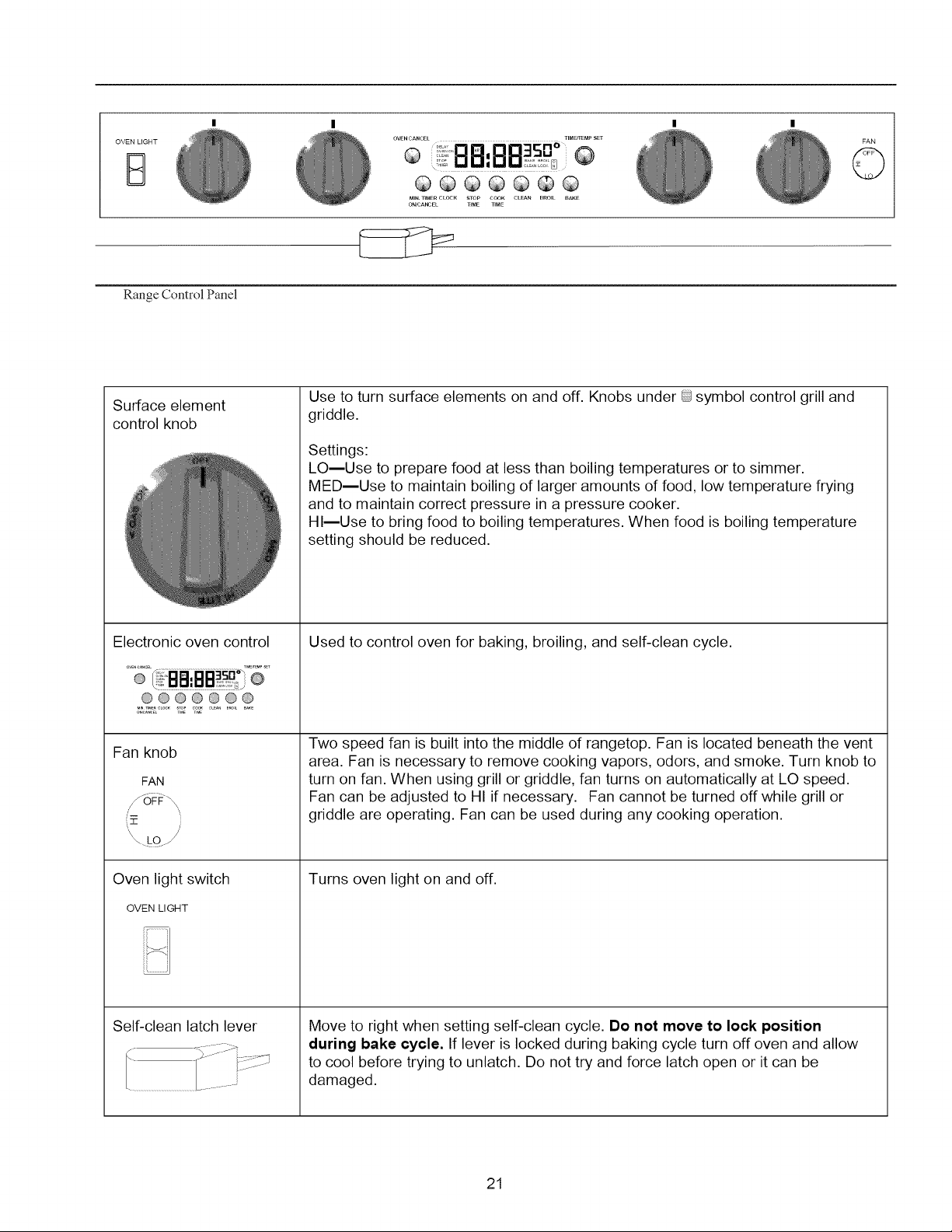
Range Control Panel
Surface element
control knob
@@@@@@@
MIN. 11MER CLOCK STOP COOK CLBN BROIL BAKE
_/CANCEL TIME TIME
Use to turn surface elements on and off. Knobs under @symbol control grill and
griddle.
Settings:
LO--Use to prepare food at less than boiling temperatures or to simmer.
MED--Use to maintain boiling of larger amounts of food, low temperature frying
and to maintain correct pressure in a pressure cooker.
HI--Use to bring food to boiling temperatures. When food is boiling temperature
setting should be reduced.
©
Electronic oven control
@@@@@@@
Fan knob
FAN
i,::z: /
Oven light switch
OVEN LIGHT
Self-clean latch lever
Used to control oven for baking, broiling, and self-clean cycle.
Two speed fan is built into the middle of rangetop. Fan is located beneath the vent
area. Fan is necessary to remove cooking vapors, odors, and smoke. Turn knob to
turn on fan. When using grill or griddle, fan turns on automatically at LO speed.
Fan can be adjusted to HI if necessary. Fan cannot be turned off while grill or
griddle are operating. Fan can be used during any cooking operation.
Turns oven light on and off.
Move to right when setting self-clean cycle. Do not move to lock position
during bake cycle. If lever is locked during baking cycle turn off oven and allow
to cool before trying to unlatch. Do not try and force latch open or it can be
damaged.
21

OVENCANCEL
TIME/TEMP SET
TIMER _ CLEAN
MIN. TIMER CLOCK STOP COOK CLEAN BROIL BAKE
ON/CANCEL TIME TIME
Electronic Range Control
Pad Description
OVEN CANCEL Cancels any cooking or cleaning function except timer.
MIN. TIMER Use to time any kitchen function or cancel timer. Does not control bake, broil, or
ON / CANCEL clean function.
CLOCK Use to set time of day.
STOP TIME Use to set delayed bake and self-clean.
COOK TIME Use to set timed baking.
CLEAN Use to select self-clean cycle.
BROIL Use to select broil.
BAKE Use to select bake.
,, U U
TIME / TEMP SET Use to set temperature or time.
Display Glossary
TIME or HR TIME displays while time-of-day is entered. TIME HR displays when time is
entered for timed or delayed baking or delayed self-cleaning.
TIMER TIMER displays while setting timer.
BAKE BAKE displays while bake oven temperature is entered and when oven bakes.
ON Displays when oven is heating.
STOP Displays when setting the stop time for a delayed baking or self-clean cycle.
BROIL Displays when broil is set and is broiling.
CLEAN Displays when self-clean cycle is entered and set.
LOCK LOCK flashes while oven door is locking and remains in display while door is
locked. After cycle is complete and oven has cooled to a safe temperature, LOCK
no longer displays and door can be opened.
22

Oven Signals
Timer signal When time elapses, timer beeps 3 times then approximately once every 6-8
seconds.
Preheat signal After setting oven to bake and selecting a temperature, oven preheats. When
oven reaches set temperature, 1-second signal sounds.
End-of-Cycle signal When a timed cooking cycle is complete, three long signals sound. End of cycle
signal continues to sound until OVEN CANCEL pad is pushed.
If minute timer end of cycle signal is sounding, push TIMER ON/OFF pad.
Other Features
12-hour automatic Cancel This safety feature prevents oven from continuing to operate if it has been left on
for over 12 hours. If a cooking function continues longer than 12 hours without
any options on oven control being touched, this feature turns oven off. Any time
an option is touched, 12-hour automatic cancel is reset.
Service Codes and Tones
Electronic range control is equipped with a self diagnostic system. Self diagnostic
system alerts you if there is a error or problem in the control. If electronic range
control sounds a series of short, rapid beeps for over 16 seconds and display
shows a F-code, record the F-code shown. Some F-codes can be cleared by
touching CANCEL or disconnecting power to the range. If the code continues to
reoccur call an authorized servicer. Disconnect electrical supply to range and
contact an authorized servicer.
Operation
Setting Clock
1. Press CLOCKpad.
2. Turn TIME/TEMP SET knob until correct time of day
is displayed.
3. PressOVEN CANCEL pad.
Setting Minute Timer
1. PressTIMER ON/OFF pad.
2. Turn TIME/TEMP SET knob until desired amount of
time is displayed. Timer can be set from 5 seconds
to 9 hours and 55 minutes.
Canceling Minute Timer
Press and hold the TIMER ON/OFF pad for 3 seconds.
• When canceling minute timer do not press OVEN
CANCEL pad. Pressing OVEN CANCEL pad cancels
cooking function.
Prepare to BaRe
CAUTION
To reduce risk of food poisoning due to bacterial
growth and production of toxins, never hold meat, milk,
fish or eggs for more than 2 hours before cooking.
Remove items Stored in Oven
Remove any pans and other cooking utensils stored in
oven.
23
Remove Items Storedin Oven

Oven Rack Placement
Position oven rack before turning oven on.
WARNING 1
To avoid damaging oven liner or creating fire, do not
line oven bottom or oven racks with foil.
1. Pull rack forward to stop position.
2. Raise front edge of rack and pull until rack is out of
oven.
3. Place rack in new rack position.
• Curved edge of rack must be toward rear of oven.
Oven Rack Placement
Bake Pan Placement
• Keep pans and baking sheets 2 inches from oven walls.
• Stagger pans placed on different racks so one is not
directly over the other.
7
=#
Pan Placement
Baking
Open oven door to confirm nothing is stored in oven cavity
and set racks to proper height before baking. Preheat
approximately 10-15 minutes before placing food inside
oven.
1. Press BAKE pad.
2. Turn TIME/TEMP SET knob until desired temperature
is displayed.
• Temperature can be set from 170°F to 550°F in 5
degree increments.
• Temperature starts at 100°F and increases in 5°
increments until reaching set temperature. Some
minor smoking is normal when using oven for first
time.
• When cook temperature is reached oven signal
sounds for approximately I second.
3. Press OVEN CANCEL pad when finished.
• Remove food from oven when cooking time has
elapsed. Food left in oven can overcook.
Timed Baking
Set oven to cook for desired amount of time. Oven
automatically stops heating after time elapses.
1. Place food in oven.
2. Press COOK TIME pad.
3. Turn TIME/TEMP SET knob until cooking time is
displayed.
• Cook time can be set up to 11 hours and 55
minutes.
• 10 minutes minimum cooking time.
4. Press BAKE pad.
5. Turn TIME/TEMP SET knob until desired temperature
is displayed.
• Temperature can be set from 170°Fto550°F in 5°
increments.
• Temperature display increases in 5°F increments
starting at 100°F until reaching set temperature.
Some minor smoking is normal when using oven for
first time. When cook temperature is reached oven
signals.
• To view cook time, press and hold COOK TIME
pad.
• When cooking time has elapsed, an end of cycle
signal sounds, oven automatically turns off and
display returns to time of day. Oven signal sounds 3
times, then once, approximately every 5 seconds
for 5 minutes or until OVEN CANCEL pad is
pressed.
To Cancel Remaining Cooking Time
Press OVEN CANCEL pad.
24