

Page 1
30" (76.2 CM) AND 36" (91.4 CM) GAS
IMPORTANT:
Installer:
Homeo
IMPOR
Installateur
Pr
.
COOKTOP INSTALLATION INSTRUCTIONS
INSTRUCTIONS D’INSTALLATION DE
LA TABLE DE CUISSON À GAZ DE
30" (76,2 CM) ET DE 36" (91,4 CM)
Table of Contents/Table des matières
COOKTOP SAFETY ........................................................................1
INSTALLATION REQUIREMENTS .................................................3
Tools and Parts .............................................................................3
Location Requirements ................................................................3
Electrical Requirements ...............................................................7
Gas Supply Requirements ...........................................................7
INSTALLATION INSTRUCTIONS ...................................................9
Install Cooktop .............................................................................9
Make Gas Connection .................................................................9
Complete Installation .................................................................11
GAS CONVERSIONS ....................................................................11
Propane Gas Conversion ...........................................................11
Natural Gas Conversion .............................................................14
SÉCURITÉ DE LA TABLE DE CUISSON .....................................17
EXIGENCES D’INSTALLATION ...................................................19
Outils et pièces ...........................................................................19
Exigences d’emplacement .........................................................19
Spécifications électriques ..........................................................23
Spécifications de l’alimentation en gaz .....................................23
INSTRUCTIONS D’INSTALLATION .............................................25
Installation de la table de cuisson ..............................................25
Raccordement au gaz ................................................................25
Terminer l’installation ..................................................................27
CONVERSIONS POUR CHANGEMENT DE GAZ ......................27
Conversion pour l’alimentation au propane ..............................27
Conversion pour l’alimentation au gaz naturel ..........................30
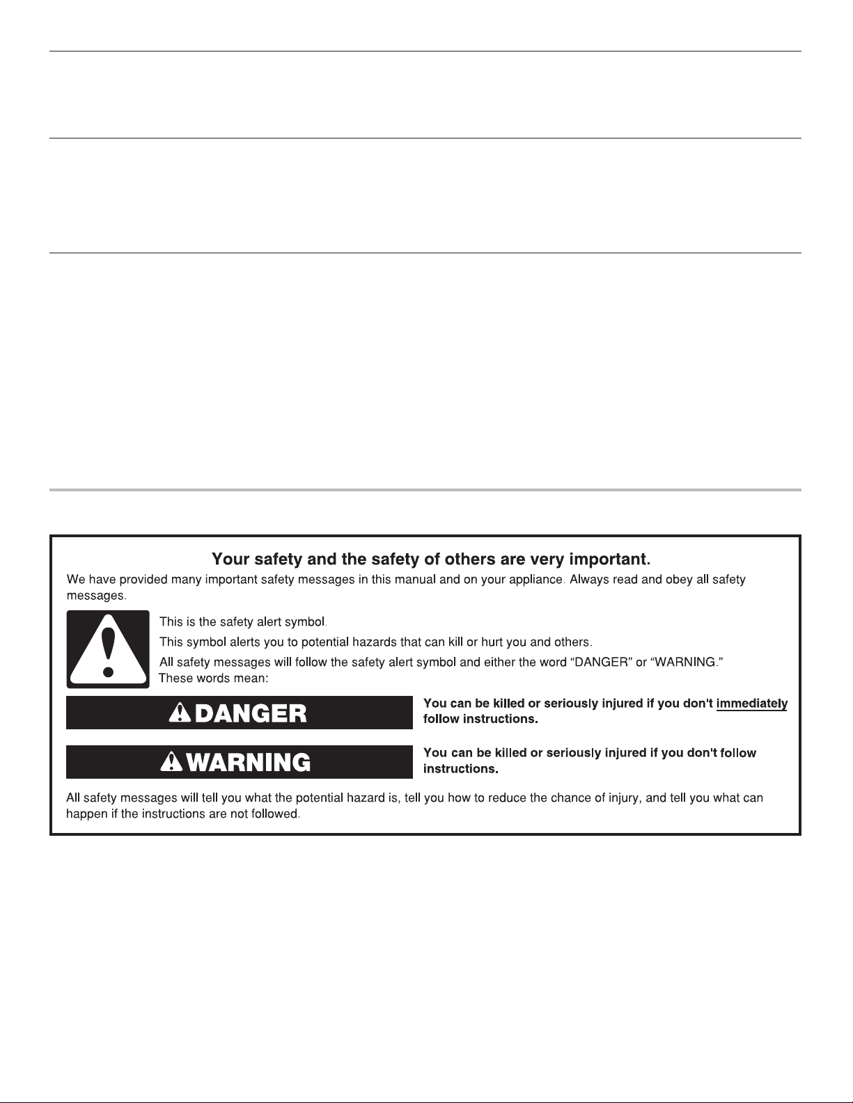
COOKTOP SAFETY
Leave installation instructions with the homeowner.
wner: Keep installation instructions for future reference.
opriétaire : Conserver les instructions d'installation pour référence ultérieure
W11100531A
TANT :
: Remettre les instructions d'installation au propriétaire.
Page 2
WARNING: If the information in these instructions is not followed exactly, a fire or
explosion may result causing property damage, personal injury or death.
– Do not store or use gasoline or other flammable vapors and liquids in the vicinity of this
or any other appliance.
– WHAT TO DO IF YOU SMELL GAS:
Do not try to light any appliance.
•
Do not touch any electrical switch.
•
Do not use any phone in your building.
•
Immediately call your gas supplier from a neighbor's phone. Follow the gas supplier's
•
instructions.
If you cannot reach your gas supplier, call the fire department.
•
Installation and service must be performed by a qualified installer, service agency or
–
the gas supplier.
WARNING: Gas leaks cannot always be detected by smell.
Gas suppliers recommend that you use a gas detector approved by UL or CSA.
For more information, contact your gas supplier.
If a gas leak is detected, follow the “What to do if you smell gas” instructions.
IMPORTANT: Do not install a ventilation system that blows air downward toward this gas cooking appliance. This type of
ventilation system may cause ignition and combustion problems with this gas cooking appliance resulting in personal injury or
unintended operation.
In the State of Massachusetts, the following installation instructions apply:
■ Installations and repairs must be performed by a qualified or licensed contractor, plumber, or gas fitter qualified or licensed by
the State of Massachusetts.
■ Acceptable Shut-off Devices: Gas Cocks and Ball Valves installed for use shall be listed.
■ A flexible gas connector, when used, must not exceed 4 feet (121.9 cm).
2
Page 3
INSTALLATION REQUIREMENTS
Tools and Parts
Gather the required tools and parts before starting installation.
Tools needed
■ Tape measure
■ Flat-blade screwdriver
■ Phillips screwdriver
■ 15/16" (24 mm)
combination wrench
■ Pipe wrench
■ Wrench or pliers
■ Marker or pencil
■ Pipe-joint compound
resistant to Propane gas
■ Noncorrosive leak-
detection solution
Parts supplied
■ Gas pressure regulator
■ Burner grates
■ Burner bases
■ Burner caps
■ Clamp brackets (2)
1
■ 2
/2" (6.4 cm) clamping screws (2)
Parts needed
Check local codes and consult gas supplier. Check existing gas
supply and electrical supply. See the “Electrical Requirements”
and “Gas Supply Requirements” sections.
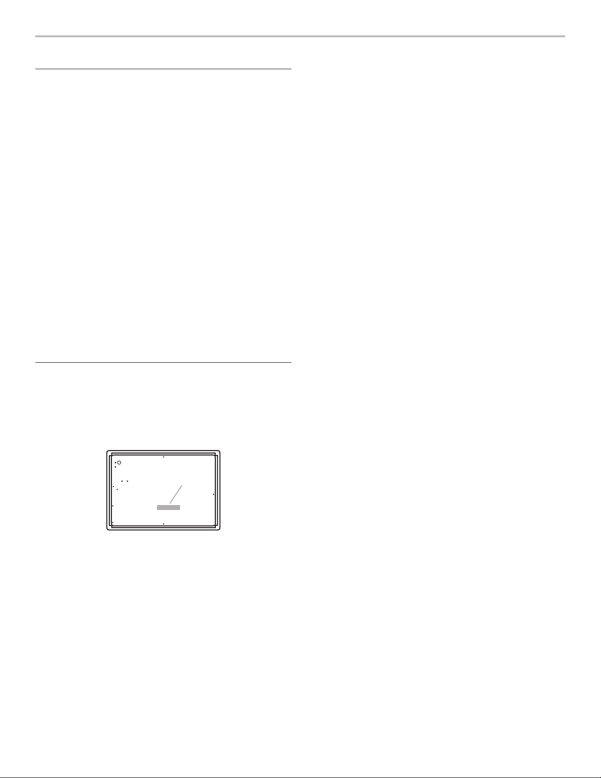
Location Requirements
IMPORTANT: Observe all governing codes and ordinances.
Do not obstruct flow of combustion and ventilation air.
■ It is the installer’s responsibility to comply with installation
clearances specified on the model/serial/rating plate. The
model/serial/rating plate is located on the underside of the
cooktop base.
A
■ Ovens approved for this type of installation will have an
approval label located on the top of the oven. If you do
not find this label, contact your dealer to confirm that your
oven is approved. Refer to oven manufacturer’s Installation
Instructions for approval for built-in undercounter use and
proper cutout dimensions.
■ The cooktop should be installed in a location away from
strong draft areas, such as windows, doors, and strong
heating vents or fans.
■ All openings in the wall or floor where cooktop is to be
installed must be sealed.
■ Cabinet opening dimensions that are shown must be used.
Given dimensions are minimum clearances.
■ Grounded electrical supply is required. See the “Electrical
Requirements” section.
■ Proper gas supply connection must be available. See the
“Gas Supply Requirements” section.
■ The cooktop is designed to hang from the countertop by its
side or rear flanges.
■ The gas and electric supply should be located as shown in
“Gas and Electric Connection Locations” in the “Location
Requirements” section so that they are accessible without
requiring removal of the cooktop.
■ Provide cutout in right rear corner of cutout enclosure as
shown to provide clearance for gas inlet, power supply cord,
and to allow the rating label to be visible.
IMPORTANT: To avoid damage to your cabinets, check with
your builder or cabinet supplier to make sure that the materials
used will not discolor, delaminate, or sustain other damage.
Mobile Home: Additional Installation Requirements
The installation of this cooktop must conform to the
Manufactured Home Construction and Safety Standard, Title 24
CFR, Part 3280 (formerly the Federal Standard for Mobile Home
Construction and Safety, Title 24, HUD Part 280). When such
standard is not applicable, use the Standard for Manufactured
Home Installations, ANSI A225.1/NFPA 501A or local codes.
In Canada, the installation of this cooktop must conform with
the current standards CAN/CSA — A240-latest edition — or with
local codes.
A. Model/serial/rating plate
■ The cooktop must be a specified cooktop that is approved
to be installed either alone or over an undercounter built-in
oven. Check the cooktop base approved installation label for
your cooktop model number and approved combinations of
cooktops and ovens that can be installed. If you do not find
this label, your cooktop may not be approved for use over an
undercounter built-in oven. Contact your dealer to confirm
that your cooktop is approved.
3
Page 4
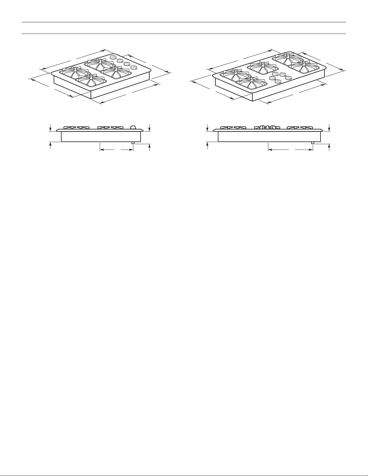
Product Dimensions
30" (76.2 cm) Models 36" (91.4 cm) Models
B
A
D
E
C
A
F
E
G
A. 21" (53.3 cm)
1
B. 29
/2" (74.9 cm)
15
C. 19
/16" (50.6 cm)
1
D. 28
/2" (72.4 cm)
3
E. 3
/16" (9.7 cm)
1
F. 5
/4" (13.3 cm)
1
G. 12
/4" (31.1 cm)
B
A. 21" (53.3 cm)
B. 36" (91.4 cm)
15
C. 19
/16" (50.6 cm)
1
D. 34
/2" (87.6 cm)
3
E. 3
/16" (9.7 cm)
1
F. 5
/4" (13.3 cm)
1
G. 15
/4" (38.7 cm)
C
D
F
G
4
Page 5
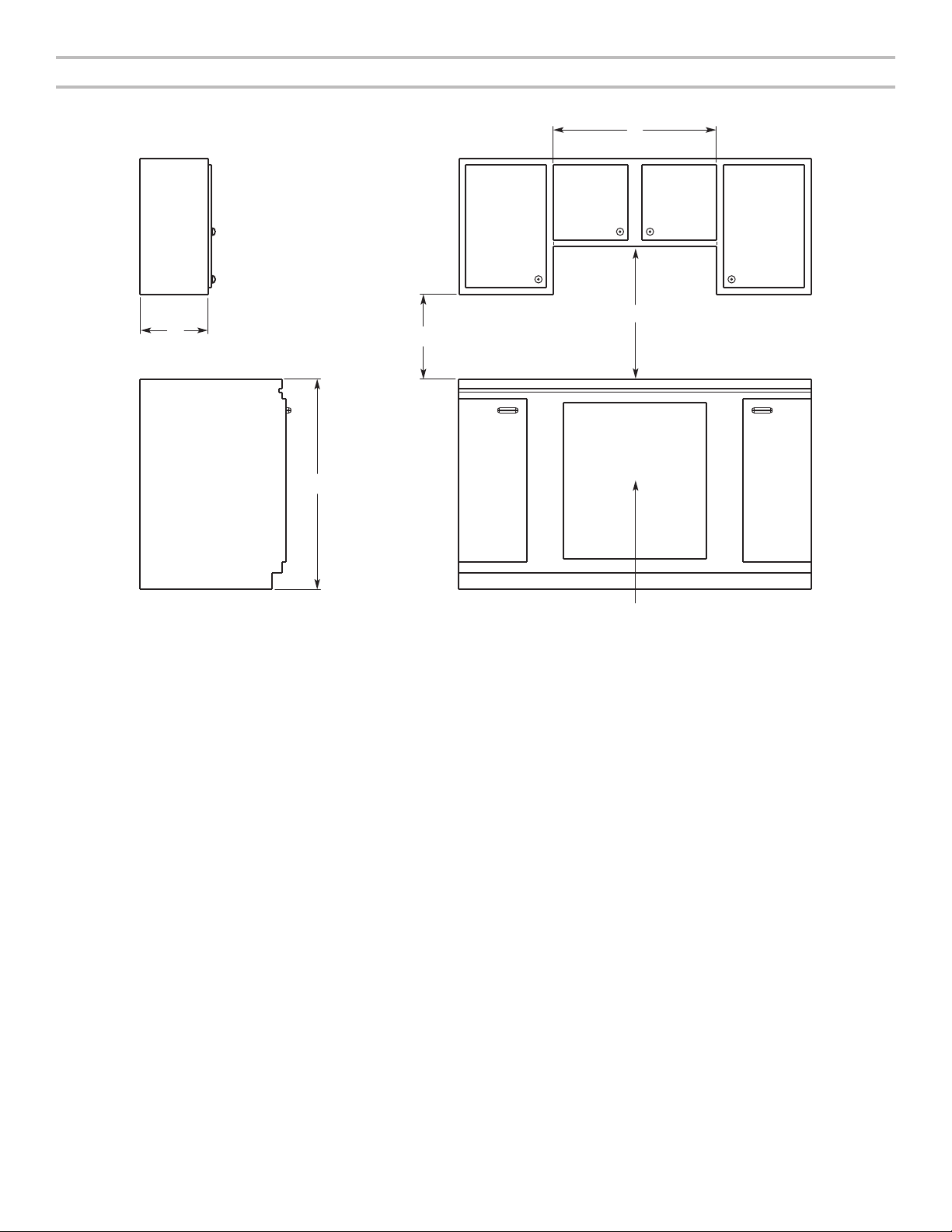
Cabinet Clearances
A
Side View Front View
B
D
C
E
F
A. 13" (33.0 cm) recommended upper cabinet depth.
B. 30" (76.2 cm) for 30" models; 36" (91.4 cm) for 36" models.
C. 18" (45.7 cm) minimum clearance from upper cabinet to countertop
within minimum horizontal clearances to cooktop.
D. 30" (76.2 cm) minimum clearance between top of cooktop platform and bottom
of uncovered wood or metal cabinet (24" [61 cm] minimum clearance if bottom of
wood or metal cabinet is covered by not less than 1/4" [6.4 mm] flame retardant
millboard covered with not less than No. 28 MSG sheet steel, 0.015" [0.4 mm]
stainless steel, or 0.024" [0.6 mm] aluminum or 0.020" [0.5 mm] copper)
E. 36" (91.4 cm) top of countertop to floor.
F. Gas line opening:
Wall: anywhere 5" (12.7 cm) below underside of countertop.
Cabinet floor: anywhere within 6" (15.2 cm) of rear wall is recommended.
5
Page 6

Cutout Dimensions: Top View
D
Back Wall
B
Side Wall
I
Countertop Front Edge
Cutout (Product Opening) Dimensions
Models A B
Min Recommended Max Min Recommended Max
30" (76.2 cm)
36" (91.4 cm)
NOTES: After making the countertop cutout, some installations may require notching down the base cabinet side walls to clear
the cooktop base. To avoid this modification, use a base cabinet with sidewalls wider than the cutout.
If cabinet has a drawer, a 4" (10.2 cm) depth clearance from the countertop to the top of the drawer (or other obstruction) in base
cabinet is required. The drawer depth may need to be shortened to avoid interfering with the regulator.
IMPORTANT: If a built-in wall oven is to be installed below this cooktop, the grounded outlet and gas supply piping must be located
in an adjacent cabinet.
This cooktop and its gas and electrical supply sources must be installed before the undercounter built-in wall oven is installed.
287/16" (72.2 cm) 281/2" (72.4 cm) 289/16" (72.6 cm) 197/8" (50.4 cm) 1915/16" (50.6 cm) 20" (50.8 cm)
347/16" (87.4 cm) 341/2" (87.6 cm) 349/16" (87.8 cm) 197/8" (50.4 cm) 1915/16" (50.6 cm) 20" (50.8 cm)
Side Walls (Combustible Surfaces)
Models H and I
All Models
Back Wall and Countertop Front Dimensions
Models C D E
All Models
25" (63.5 cm) 33/8" (8.6 cm) 21/8" (5.4 cm)
A
H
E
Both have to be 6" (15.24 cm) or more.
C
Side Wall
6
Page 7

Electrical Requirements
IMPORTANT: The cooktop must be electrically grounded in
accordance with local codes and ordinances, or in the absence
of local codes, with the National Electrical Code, ANSI/NFPA 70
or Canadian Electrical Code, CSA C22.1.
If codes permit and a separate ground wire is used, it is
recommended that a qualified electrical installer determine
that the ground path is adequate.
A copy of the above code standards can be obtained from:
National Fire Protection Association
1 Batterymarch Park
Quincy, MA 02169-7471
CSA International
8501 East Pleasant Valley Road
Cleveland, OH 44131-5575
■ A 120-volt, 60 Hz., AC-only, 15-amp fused, electrical circuit
is required. A time-delay fuse or circuit breaker is also
recommended. It is recommended that a separate circuit
serving only this cooktop be provided.
■ Electronic ignition systems operate within wide voltage limits,
but proper grounding and polarity are necessary. Check that
the outlet provides 120-volt power and is correctly grounded
and polarized.
■ The wiring diagrams are provided with this cooktop. See the
Wiring Diagrams. The wiring diagrams are located on the left
underside of the cooktop base.
Gas Supply Requirements
WARNING
Explosion Hazard
Use a new CSA International approved gas supply line.
Install a shut-off valve.
Securely tighten all gas connections.
If connected to propane, have a qualified person make
sure gas pressure does not exceed 14" (36 cm) water
column.
Examples of a qualified person include:
licensed heating personnel,
authorized gas company personnel, and
authorized service personnel.
Failure to do so can result in death, explosion, or fire.
Observe all governing codes and ordinances.
IMPORTANT: This installation must conform with all local codes
and ordinances. In the absence of local codes, installation must
conform with American National Standard, National Fuel Gas
Code ANSI Z223.1—latest edition or CAN/CGA B149—latest
edition.
IMPORTANT: Leak testing of the cooktop must be conducted
according to the manufacturer’s instructions.
Type of Gas
Natural Gas:
This cooktop is factory-set for use with Natural gas. To convert
to Propane gas, see the Gas Conversion instructions provided
in the package containing the literature. The model/serial/
rating plate located on the underside of the cooktop base has
information on the types of gas that can be used. If the types
of gas listed do not include the type of gas available, check
with the local gas supplier.
Propane Gas conversion:
Conversion must be done by a qualified service technician.
No attempt shall be made to convert the appliance from the gas
specified on the model/serial/rating plate for use with a different
gas without consulting the serving gas supplier. See the Gas
Conversion instructions provided in the package containing
the literature.
7
Page 8

Gas Supply Line
Gas Pressure Regulator
■ Provide a gas supply line of 3/4" (19 mm) rigid pipe to the
cooktop location. A smaller size pipe on longer runs may
result in insufficient gas supply. Pipe-joint compounds that
resist the action of Propane gas must be used. Do not use
TEFLON®† tape. With Propane gas, piping or tubing size can
be 1/2" (13 mm) minimum. Usually, Propane gas suppliers
determine the size and materials used in the system.
Flexible metal appliance connector:
■ If local codes permit, use a 1/2" or 3/4" (13 mm or
19 mm) flexible stainless steel tubing gas connector,
designed by CSA to connect the cooktop to the rigid
gas supply line.
■ A 1/2" (13 mm) male pipe thread is needed for
connection to the female pipe threads of the inlet
to the appliance pressure regulator.
■ Do not kink or damage the flexible metal tubing when
moving the cooktop.
■ Must include a shut-off valve:
Install a manual gas line shut-off valve in an easily accessible
location. Do not block access to shut-off valve. The valve is
for turning on or shutting off gas to the cooktop.
B
A
C
A. Gas supply line
B. Shut-off valve open position
C. To cooktop
The gas pressure regulator supplied with this cooktop must be
used. The inlet pressure to the regulator should be as follows for
proper operation:
Natural Gas:
Minimum pressure: 12.7 cm WCP
Maximum pressure: 17.8 cm to 35.6 cm WCP
Propane Gas:
Minimum pressure: 25.4 cm cm WCP
Maximum pressure: 17.8 cm to 35.6 cm WCP
Contact local gas supplier if you are not sure about the
inlet pressure.
Burner Input Requirements
Input ratings shown on the model/serial/rating plate are for
elevations up to 2,000 ft (609.6 m).
For elevations above 2,000 ft (609.6 m), ratings are reduced
at a rate of 4% for each 1,000 ft (304.8 m) above sea level
(not applicable for Canada).
Gas Supply Pressure Testing
Gas supply pressure for testing regulator must be at least
2.5 cm water column pressure above the manifold pressure
shown on the model/serial rating plate.
Line pressure testing above 1/2 psi (3.5 kPa) gauge
(35.6 cm WCP)
The appliance and its individual shut-off valve must be
disconnected from the gas supply piping system during any
pressure testing of that system at test pressures in excess of
1/2 psi (3.5 kPa).
Line pressure testing at 1/2 psi (3.5 kPa) gauge
(35.6 cm WCP) or lower
The appliance must be isolated from the gas supply piping
system by closing its individual manual shut-off valve during
any pressure testing of the gas supply piping system at test
pressures equal to or less than 1/2 psi (3.5 kPa).
†®TEFLON is a registered trademark of Chemours.
8
Page 9

INSTALLATION INSTRUCTIONS
Install Cooktop
WARNING
Excessive Weight Hazard
Use two or more people to move and install cooktop.
Failure to do so can result in back or other injury.
Decide on the final location for the cooktop. Avoid drilling into or
severing existing wiring during installation.
1. Determine whether your cabinet construction provides
clearance for installing clamping brackets at cooktop base
ends. This is the recommended location. Clamping brackets
can be installed on the front and back of cooktop base
bottom, if necessary.
B
A
A. Attachment screw holes for optional front and back location
B. Cooktop base bottom
C. Attachment screw
D. Clamping bracket (and locations recommended)
2. Using two or more people, place cooktop right side up into
the cutout.
NOTE: Make sure that the front edge of the cooktop is
parallel to the front edge of the countertop. If repositioning
is needed, lift entire cooktop up from cutout to avoid
scratching the countertop.
3. Remove the attachment screws for the selected bracket
locations from the bottom of the cooktop base.
C
D
A
B
4. Attach brackets to cooktop base bottom with bracket
attachment screws. Securely tighten screws.
A
B
C
A. Cooktop
B. Cooktop base
C. 2" (5.1 cm) bracket attachment screw
D. Clamping bracket (extends far
enough beyond cooktop base to
allow installation of clamping screws)
E. Countertop
E
D
Make Gas Connection
WARNING
Explosion Hazard
Use a new CSA International approved gas supply line.
Install a shut-off valve.
Securely tighten all gas connections.
If connected to propane, have a qualified person make
sure gas pressure does not exceed 14" (36 cm) water
column.
Examples of a qualified person include:
licensed heating personnel,
authorized gas company personnel, and
authorized service personnel.
Failure to do so can result in death, explosion, or fire.
A. Edge of cooktop base bottom
B. Clamping bracket
Typical flexible connection
1. Apply pipe-joint compound made for use with Propane gas
to the larger thread ends of the flexible connector adapters
(see C and G in the following illustration).
2. Attach one adapter to the gas pressure regulator and
the other adapter to the gas shut-off valve. Tighten both
adapters.
9
Page 10

3. Use a 15/16" (24 mm) combination wrench and channel lock
pliers to attach the flexible connector to the adapters. Check
that connector is not kinked.
IMPORTANT: All connections must be wrench-tightened.
Do not make connections to the gas regulator too tight.
Making the connections too tight may crack the regulator
and cause a gas leak. Do not allow the regulator to turn
when tightening fittings.
No appliance/obstructions
below cooktop
Suggested installation to
avoid interference below
cooktop
4. Install the pressure regulator with the arrow pointing in
the direction toward the bottom of the cooktop base and
in a position where you can reach the regulator access cap.
B
A
C
D
A
B
C
D
E
F
G
H
I
A. Manifold entrance
B. Gas pressure regulator
C. Use pipe-joint compound.
D. Adapter (must have 1/2"
[13 mm] male pipe thread)
E. Flexible connector
F. Adapter
G. Use pipe-joint compound.
H. Manual gas shut-off valve
I. 1/2" (13 mm) or 3/4" (19 mm)
gas pipe
A
B
C
D
E
E
G
H
I
J
K
A. Manifold entrance
B. 3/8" (10 mm) elbow
C. Use pipe-joint compound.
D. Adapter (must have 3/8"
[10 mm] male pipe thread)
E. Flexible connector (pass
through wall between cabinets)
F. Adapter (must have 3/8"
[10 mm] male pipe thread)
G. Use pipe-joint compound.
H. Appliance pressure regulator
(supplied)
I. 1/2" (13 mm) or 3/4" (19 mm)
gas pipe
J. Manual gas shut-off valve
K. 1/2" (13 mm) or 3/4" (19 mm)
gas pipe
A. Access cap
B. Rear of cooktop
C. Gas pressure regulator
D. Up arrow. The regulator must be installed with
the arrow pointing toward the cooktop bottom.
Use only pipe-joint compound made for use with Natural and
Propane gas.
Do not use TEFLON® tape. You will need to determine the fittings
required depending on your installation.
Complete Connection
1. Open the manual shut-off valve in the gas supply line. The
valve is open when the handle is parallel to the gas pipe.
A
B
A. Closed valve
B. Open valve
2. Test all connections by brushing on an approved
noncorrosive leak-detection solution. If bubbles
appear, a leak is indicated. Correct any leak found.
3. Remove surface burner caps and grates from parts package.
Align notches in burner caps with pins in burner base.
Burner caps must be positioned properly and level in order
for the surface burners to light.
4. Place burner grates over burners and caps.
10
5. Plug into a grounded 3 prong outlet.
Page 11

Complete Installation
A
B
Electronic Ignition System
Initial lighting and gas flame adjustments
Surface burners use electronic igniters in place of standing
pilots. When the cooktop control knob is turned to Lite, the
system creates a spark to light the burner. This sparking
continues as long as the control knob is turned to Lite.
Check Operation of Surface Burners
1. Push in and turn the surface burner control knobs to LITE.
The surface burner flame should light within 4 seconds.
The first time a surface burner is lit, it may take longer than
4 seconds to light because of air in the gas line.
2. Turn the control knob to HIGH and check for a blue-colored
flame. It should be clean and soft in character. No yellow tip,
blowing, or lifting of flame should occur. Occasional orange
flashes are normal and reflect different elements in the air
or gas.
3. After verifying the proper burner operation, turn the control
knobs to OFF.
If burners do not light properly:
■ Turn the surface burner control knob to OFF.
■ Check that the power supply cord is plugged in and the
circuit breaker has not tripped or the fuse blown.
■ Check that the gas shut-off valve is set to the open position.
■ Check that the burner bases and caps are properly
positioned on the burners.
Recheck the operation of the surface burners. If a burner does
not light at this point, contact your dealer or authorized service
company for assistance.
Check Flame Height
Adjust the height of surface burner flames.
The surface burner low flame should be a steady blue flame
approximately 1/4" (6.4 mm) high.
GAS CONVERSIONS
IMPORTANT: Gas conversions from Natural gas to Propane gas
must be done by a qualified installer.
WARNING
Explosion Hazard
Use a new CSA International approved gas supply line.
Install a shut-off valve.
Securely tighten all gas connections.
If connected to propane, have a qualified person make
sure gas pressure does not exceed 14" (36 cm) water
column.
Examples of a qualified person include:
licensed heating personnel,
authorized gas company personnel, and
authorized service personnel.
Failure to do so can result in death, explosion, or fire.
Propane Gas Conversion
1. Turn the manual shut-off valve to the closed position.
B
A
C
A. To cooktop
B. Shut-off valve (closed position)
C. Gas supply line
2. Unplug cooktop or disconnect power.
A. Low flame
B. High flame
11
Page 12

Convert Gas Pressure Regulator
Replace All Orifice Spuds
1. Remove the access cap by using a wrench to turn the
access cap counterclockwise.
Remove spring retainer from the cap by pushing against
the flat side of the spring retainer. Look at the spring retainer
to locate the “NAT” or “LP” position. Turn over the spring
retainer so the “LP” is showing on the bottom. Snap the
spring retainer back into the cap. Reinstall the cap onto
the regulator.
A
B
CDE
A. Access cap
B. Gasket
C. Gas pressure regulator
D. “LP” position
E. “NAT” position
2. Test the gas pressure regulator and gas supply line.
The regulator must be checked at a minimum 2.5 cm water
column above the set pressure. The inlet pressure to the
regulator should be as follows for operation and checking
the regulator setting:
Propane Gas:
Minimum pressure: 25.4 cm WCP.
Supply pressure: 35.6 cm WCP.
Gas Supply Pressure Testing
Line pressure testing above 1/2 psi (3.5 kPa) gauge
(35.5 cm WCP)
The cooktop and its individual shut-off valve must be
disconnected from the gas supply piping system during
any pressure testing of that system at test pressures in
excess of 1/2 psi (3.5 kPa).
Line pressure testing at 1/2 psi (3.5 kPa) gauge
(35.5 cm WCP) or lower
The cooktop must be isolated from the gas supply piping
system by closing its individual manual shut-off valve during
any pressure testing of the gas supply piping system at test
pressures equal to or less than 1/2 psi (3.5 kPa).
1. Remove the grates and burner caps.
2. Remove the burner base by removing two screws.
3. Apply masking tape to the end of a 7 mm nut driver to help
hold the gas orifice spud in the nut driver while changing it.
Insert nut driver into the gas opening, and press down onto
the gas orifice spud, then remove by turning the gas orifice
spud counterclockwise and lifting out. Set gas orifice spud
aside.
A
B
C
F
D
G
D
E
A. Burner cap
B. Inner locating ring
C. Burner base
D. Orifice holder
E. Electrode
F. 7 mm nut driver
G. Orifice spud
4. Replace with correct Propane gas orifice spud. The spuds
have small numbers stamped on the side. This number
codes the orifice diameter and its correct burner location.
A
A. Size stamp
Propane Gas Orifice Spud Sizes
12
Burner Location
30" (72.6 cm)
models
36" (91.4 cm)
models
Left Rear 0.91 0.91
Left Front 0.91 0.91
Center N/A 0.91
Right Rear 0.91 0.91
Right Front 0.97 0.97
5. Place Natural gas orifice in plastic parts bag for future use
and keep with the package containing literature.
NOTE: There may be extra orifices in your kit.
Page 13

6. Replace the burner base.
7. Replace burner cap.
8. Repeat steps 2 through 7 for the remaining burners.
9. Open shut-off valve in the gas supply line. The valve is open
when the handle is parallel to the gas pipe.
10. Once you have completed converting all of the cooktop
burners, test the cooktop for leaks by brushing on an
approved noncorrosive leak-detection solution. If bubbles
appear, a leak is indicated. Correct any leaks found.
4. Insert a slender, thin-blade screwdriver into knob hole. Turn
the adjusting screw clockwise until tight. Do not over tighten.
5. Replace rubber grommet and control knob.
After adjusting the screw, the burner should produce a
stable, steady blue flame of minimum size. The setting
should be checked by turning knob from high to low several
times without extinguishing the flame.
6. Repeat steps 1-5 for the remaining burners.
This operation will automatically provide the proper flame size
at medium setting.
After all conversion steps have been completed, check
the appearance of each burner flame at the Hi and Lo
settings against the illustration below. If the flames appear too
large or too small, review each step to make sure it was
completed correctly.
11. Plug in cooktop or reconnect power.
Low Flame Adjustment
This appliance is shipped from the factory with low and high
flame settings adjusted for use with Natural gas.
To set for use with Propane gas:
1. Remove control knob from valve stem.
2. Remove rubber grommet.
3. Locate the valve adjustment screw.
A
B
C
A. Knob
B. Adjustment screw
C. Knob hole (knob and
grommet removed)
Complete Installation
1. Refer to the “Make Gas Connection” section for properly
connecting the cooktop to the gas supply.
2. Refer to the “Complete Installation” section in the
“Installation Instructions” section of these instructions to
complete this procedure.
13
Page 14

Natural Gas Conversion
1. Turn the manual shut-off valve to the closed position.
B
A
C
A. To cooktop
B. Shut-off valve (closed position)
C. Gas supply line
2. Unplug cooktop or disconnect power.
Convert Gas Pressure Regulator
1. Remove the access cap by using a wrench to turn the
access cap counterclockwise.
Remove spring retainer from the cap by pushing against
the flat side of the spring retainer. Look at the spring retainer
to locate the “NAT” or “LP” position. Turn over the spring
retainer so the “NAT” is showing on the bottom. Snap the
spring retainer back into the cap. Reinstall the cap onto
the regulator.
A
B
Natural Gas:
Minimum pressure: 12.7 cm WCP.
Supply pressure: 35.6 cm WCP.
Gas Supply Pressure Testing
Line pressure testing above 1/2 psi (3.5 kPa) gauge
(35.5 cm WCP)
The cooktop and its individual shut-off valve must be
disconnected from the gas supply piping system during
any pressure testing of that system at test pressures in
excess of 1/2 psi (3.5 kPa).
Line pressure testing at 1/2 psi (3.5 kPa) gauge
(35.5 cm WCP) or lower
The cooktop must be isolated from the gas supply piping
system by closing its individual manual shut-off valve during
any pressure testing of the gas supply piping system at test
pressures equal to or less than 1/2 psi (3.5 kPa).
Replace All Orifice Spuds
1. Remove the grates and burner caps.
2. Remove the burner base by removing two screws.
3. Apply masking tape to the end of a 7 mm nut driver to help
hold the gas orifice spud in the nut driver while changing it.
Insert nut driver into the gas opening, and press down onto
the gas orifice spud, then remove by turning the gas orifice
spud counterclockwise and lifting out. Set gas orifice spud
aside.
DE
A. Access cap
B. Gasket
C. Gas pressure regulator
D. “NAT” position
E. “LP” position
C
2. Test the gas pressure regulator and gas supply line.
The regulator must be checked at a minimum 2.5 cm water
column above the set pressure. The inlet pressure to the
regulator should be as follows for operation and checking
the regulator setting:
A
B
C
F
D
G
D
E
A. Burner cap
B. Inner locating ring
C. Burner base
D. Orifice holder
E. Electrode
F. 7 mm nut driver
G. Orifice spud
14
Page 15

4. Replace with correct Natural gas orifice spud. The spuds
have small numbers stamped on the side. This number
codes the orifice diameter and its correct burner location.
A
A. Size stamp
Natural Gas Orifice Spud Sizes
Low Flame Adjustment
To set for use with Natural gas:
1. Remove control knob from valve stem.
2. Remove rubber grommet.
3. Locate the valve adjustment screw.
A
Burner Location
30" (72.6 cm)
models
36" (91.4 cm)
models
Left Rear 1.55 1.55
Left Front 1.55 1.42
Center N/A 1.42
Right Rear 1.55 1.42
Right Front 1.85 1.73
5. Place Propane gas orifice in plastic parts bag for future use
and keep with the package containing literature.
NOTE: There may be extra orifices in your kit.
6. Replace the burner base.
7. Replace burner cap.
8. Repeat steps 2 through 7 for the remaining burners.
9. Open shut-off valve in the gas supply line. The valve is open
when the handle is parallel to the gas pipe.
10. Once you have completed converting all of the cooktop
burners, test the cooktop for leaks by brushing on an
approved noncorrosive leak-detection solution. If bubbles
appear, a leak is indicated. Correct any leaks found.
B
C
A. Knob
B. Adjustment screw
C. Knob hole (knob and
grommet removed)
4. Insert a slender, thin-blade screwdriver into knob hole. Turn
the adjusting screw counter clockwise until the flame
stabilizes and matches the pictured low setting as shown in
the following illustration.
11. Plug in cooktop or reconnect power.
15
Page 16

5. Replace rubber grommet and control knob.
3/17
After adjusting the screw, the burner should produce a
stable, steady blue flame of minimum size. The setting
should be checked by turning knob from high to low several
times without extinguishing the flame.
6. Repeat steps 1-5 for the remaining burners.
After all conversion steps have been completed, check
the appearance of each burner flame at the Hi and Lo
settings against the previous illustration. If the flames appear
too large or too small, review each step to make sure it was
completed correctly.
Complete Installation
1. Refer to the “Make Gas Connection” section for properly
connecting the cooktop to the gas supply.
2. Refer to the “Complete Installation” section in the
“Installation Instructions” section of these instructions to
complete this procedure.
16
 Loading...