

Amana AFI2538AEW12, AFI2538AES00, AFI2538AEQ, AFI2538AEQ00, AFI2538AEQ12 Installation Guide
...Page 1
Inst cti n heet
for Mid-South ice Maker Conversion to Whirlpool 8 Cube ice Maker
Kit Contains:
1 Module Cover WI0460384
1 Switch 2313326
1 Harness WI0532397
1 8 Cube ice Maker WI0377149
I tmpinger WI0121269
3 Screws 12990511
I Shut OffArm WI0378254
1 Shut OffArm Extension W!035!0!9
1 Fill Cup insert WI0372171
1 instruction Sheet W104 7 7 2 2 9
Electrical Shock Hazard
Disconnect power before servicing.
Replace all parts and panels before
operating.
Failure to do so can result in death
or electrical shock.
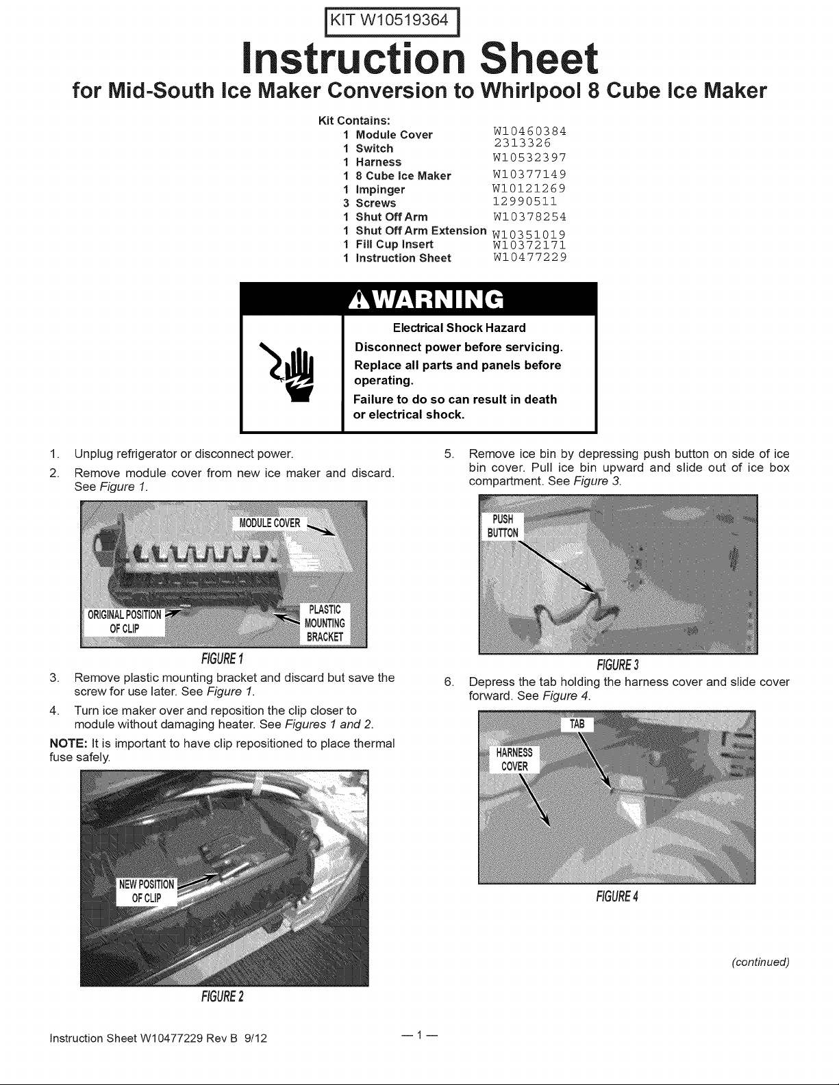
1. Unplug refrigerator or disconnect power.
2. Remove module cover from new ice maker and discard.
See Figure 1.
FIGURE!
3. Remove plastic mounting bracket and discard but save the
screw for use later. See Figure 1.
4. Turn ice maker over and reposition the clip closer to
module without damaging heater. See Figures 1 and 2.
NOTE: it is important to have clip repositioned to place thermal
fuse safely.
5. Remove ice bin by depressing push button on side of ice
bin cover. Pull ice bin upward and slide out of ice box
compartment. See Figure 3.
FIGURE3
6.
Depress the tab holding the harness cover and slide cover
forward. See Figure 4.
FIGURE2
instruction Sheet W10477229 Rev B 9/12 1
RGURE4
(continued)
Page 2
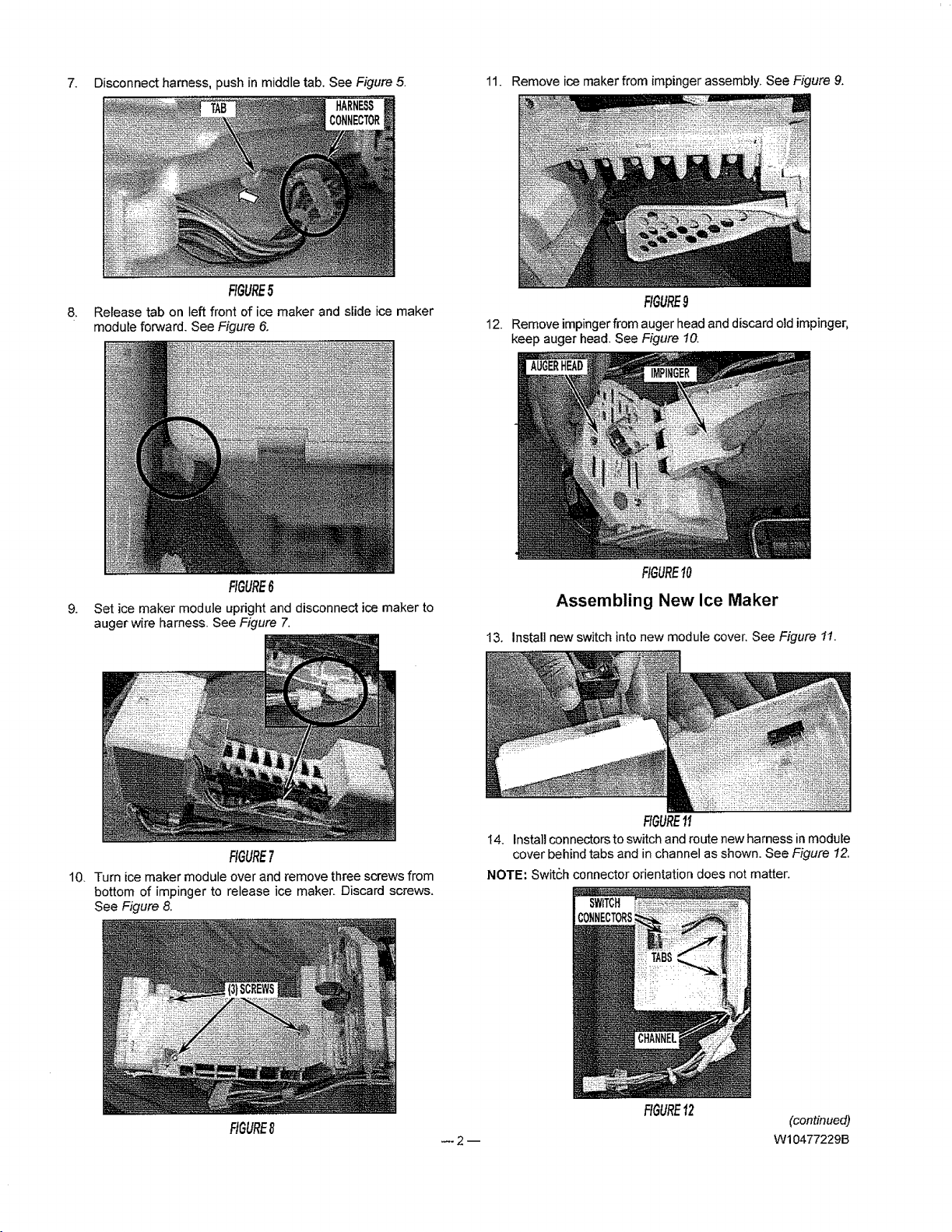
7. Disconnect harness, push in middle tab, See Figure 5, 11, Remove ice maker from impinger assembly, See Figure 9,
FIGURE5
8, Release tab on left front of ice maker and slide ice maker
module forward. See Figure 6,
FIGURE6
9, Set ice maker module upright and disconnect ice maker to
auger wire harness. See Figure 7.
FIGURE9
12. Removeimpingerfrom auger head and discard old impinger,
keep auger head. See Figure 10.
FIGURE10
Assembling New Ice Maker
13, Instal] new switch into new module cover, See Figure 11.
FIGURE7
10. Turn ice maker module over and remove three screwsfrom
bottom of impinger to release ice maker, Discard screws,
See Figure 8.
FtGURE8 (continued)
FIGURE11
t4. Install connectors to switch and route new harness in module
cover behind tabs and in channel as shown. See Figure 12.
NOTE: Swit6h connector orientation does not matter.
FIGURE12
2 W10477229B
Page 3

15.Usescrewremovedinstep3fromplasticmountingbracket
tomountH-tapon new harness to module and snap module
cover and harness assembly onto ice maker. Besure to keep
the harness in the channel. See Figure 13.
19. Lay auger on aflat surface and snap new impinger in place
(impinger tabs should face auger yoke assembly as shown),
See Figure 17.
FIGURE!3
16. Connect module connector to icemaker module.
See Figure !4.
FIGURE14
17. Slide thermal fuse into clip on ice maker. See Figure 15.
FIGURE17
20. With auger head on flat surface, install new ice maker
assembly onto top side of impinger. Squeeze impinger
and ice maker assembly together aligning holes on bottom
of impinger with mounting holes on bottom of ice maker
assembly. Install 3 screws provided with kit, See Figure 18.
FIGURE18
21. Turn assembly upright and reconnect ice maker harness.
See Figure 19.
FIGURE15
Installing New Ice Maker and Impinger
18. Cut tab off new impinger. See Figure 16.
FIGURE16
W10477229B -- 3 --
FIGURE19
(continued)
Page 4

22. Assemble shut off arm and shut off arm extension.
See Figure 20.
24. Reinstall ice maker into ice box.
25. Reconnect harness to refrigerator.
26. Reinstall harness cover.
27. Be sure ice maker switch is turned on.
28. Reinstall ice bucket.
29. Replace all parts and panels.
Electrical Shock Hazard
Plug into a grounded 3 prong outlet.
Do not remove ground prong.
Do not use an adapter.
Do not use an extension cord.
Failure to follow these instructions can result in death,
fire, or electrical shock.
FIGURE20
23. Install shut off arm assembly and fill cup insert onto new ice
maker assembly as shown.
NOTE: Push one end of the shut off arm assembly into module
and guide other end into lower hole next to fill cup. See Figure 21.
30. Plug in refrigerator or reconnect power.
31. Check ice maker operation through normal service
procedures.
FIGURE21
©Whirlpool Corporation 2012
(All Rights Reserved) 4 W10477229B
 Loading...