


WBSn-24 00 an d W BSn-2 450 User Guide
Use r Guid e
Softwa re Versi on: 1.3.2 January 2013
Docum ent Version 1.3.2.GA

WBSn-2400 and WBSn -2450 User Guide
FCC Statement
Federal Communication Commission Interference St atement
This equipme nt has been tested and found to comply with the lim its for a Class B digital dev ice, pursuant to Part 15 of the FCC Rules. These limits are designed to provide reasonable protection agai nst harmful in terference in a residential installation. T his equipme nt generates, uses and can radiate radio frequency en ergy and, if n ot installed and used in accordance with the instru ctions, may c ause harmful interference to radio communications. However, the re is no guarantee that interferenc e will not occ ur in a particular installation. If this equipment does cause harmfu l interference to radio or telev ision receptio n, which can be determin ed by turning the equipment off and on, the user is e ncouraged to try to correct the interference by one o f the following measures:
Reorient or relocate t he receiving a ntenna.
Consult the dealer or an experienced radio/TV t echnician for help.
FCC Caution: Any changes or modifica tions not expr essly approve d by the party responsible for compliance could void the user’s authority to ope rate this equipment.
This device c omplies with Part 15 of the FCC Rules. Operation is subject to the following tw o conditions: (1) This device may not caus e harmful interference, and (2) this device must accept any interfe rence receive d, including interference that may cause u ndesired operation.
For product a vailable in the USA/Canada market, only channel 1~11 can be operated. Selec tion of other channels is n ot possible.
This device and its antenna(s) must not be co-locate d or operated in conjunctio n with any o ther antenna or transmitter.
IMPORTANT NOTE:
FCC Radiation Exposure S tatement:
This equipme nt complies with FCC radiation exposur e limits set fo rth for an uncontrolled environment. T his equipment should be ins talled and op erated with minimum distance 20cm b etween the ra diator & your body.
Copyright © Wavion Wireless Networks, an Alvarion Ltd Company, 2012© Co pyright 2013 Alvarion Ltd. All rights reserved.
The material contained herein is proprie tary, privileg ed, and confi dential and o wned by Alvarion or its thi rd party licensors. No disclosure thereof shall be made to third parties with out the expr ess written pe rmission of A lvarion Ltd.
Alvarion Ltd. reserves the right to alter the equipmen t specifications and descri ptions in this publication w ithout prior notice. No pa rt of this pub lication shall be deemed t o be part of any contract or warranty un less specifically incorporated by reference into such con tract or warranty.
Limitation of Liability:
(a) Alvarion shall not be lia ble to the purchaser or to any third party, for any los s of profits, l oss of use, int erruption of business or f or any indirect, special, incidental, punitive or consequential damages of any kin d, whether arising under breach of co ntract, tort (in cluding negligence), strict liability or ot herwise and whether base d on this agreement or otherwise, ev en if advised of the possibility of such d amages.
(b) To the ex tent permitte d by applicable law, in no event shall th e liability for damages here under of Alv arion or its employees o r agents exce ed the purcha se price paid for the prod uct by purchaser, nor shall the aggregate liability for damages to all parties regarding any product exceed the purchase price paid fo r that produc t by that par ty (except in the case of a breach of a part y’s confidenti ality obligations).
WBSn-2400 and WBSn -2450 |
ii |

WBSn-2400 and WBSn -2450 User Guide |
C ontents |
|
|
|
|
C ontents |
1 |
Introductio n................................................................. |
.............. ..................- 7 - |
||
2 |
Installation |
................................................................................. |
..................- 9 - |
|
|
2.1 |
Pre-Inst allation C hecklist .... ................................................................. |
....................... - 9 - |
|
|
2.2 |
Installation and Set-up ....... ................................................................. |
..................... - 15 - |
|
|
|
2.2.1 |
Pre-Installation – Connecting to the Data Port ............................ |
..................... - 15 - |
|
|
2.2.2 |
Installing th e WBSn base station................................................. |
..................... - 17 - |
|
|
2.2.3 |
Mounting .................. ................................................................. |
..................... - 18 - |
|
|
2.2.4 |
Connecting and Seali ng antenn as .............................................. |
..................... - 18 - |
|
2.3 |
Wind Lo ading Co nsiderations ............................................................. |
..................... - 19 - |
|
|
2.4 |
Accessin g the Alvarion Management Interface................................. |
..................... - 19 - |
|
|
2.5 |
Automatic Channel Selectio n screen .................................................. |
..................... - 20 - |
|
3 |
WB Sn Set up and Managem ent ............................................... |
................- 21 - |
||
|
3.1 |
Status .. |
................................. ................................................................. |
..................... - 21 - |
|
|
3.1.1 |
Checking System Setu p .............................................................. |
..................... - 21 - |
|
|
3.1.2 |
VAPs ......................... ................................................................. |
..................... - 22 - |
|
|
3.1.3 |
Wireless As sociations. ................................................................. |
..................... - 22 - |
|
|
3.1.4 |
Radio Statu s Paramet ers ............................................................. |
..................... - 23 - |
|
3.2 |
Configuration ...................... ................................................................. |
..................... - 24 - |
|
|
|
3.2.1 |
System Setup............. ................................................................. |
..................... - 24 - |
|
|
3.2.2 |
IP Manage ment ......... ................................................................. |
..................... - 24 - |
|
|
3.2.3 |
Specifying the Time of the Base Station Unit .............................. |
..................... - 25 - |
|
|
3.2.4 |
Specifying the Locatio n of the B ase Station Unit......................... |
..................... - 26 - |
|
|
3.2.5 |
Setting Management VLAN ........................................................ |
..................... - 26 - |
|
3.3 |
Wireless Interface ................ ................................................................. |
..................... - 27 - |
|
|
|
3.3.1 |
Virtual AP (VAP)......... ................................................................. |
..................... - 27 - |
|
|
3.3.2 |
QoS (Quali ty of Service) Packet P riority ....................................... |
..................... - 28 - |
WBSn-2400 and WBSn -2450 |
|
iii |
||

WBSn-2400 and WBSn -2450 User Guide |
C ontents |
3.4 |
Security ................................ ...................................................................................... |
- 29 - |
|
|
3.4.1 |
Authentication .......... ................................................................. ..................... |
- 29 - |
|
|
3.4.1.1 EA P for GSM Subscriber Identity Modu le (EAP-SIM )......................................... |
- 29 - |
|
|
3.4.1.2 Unique Enhanc ements for Open Security Sessions........................................... |
- 30 - |
|
3.4.2 |
Encryption Methods .. ................................................................. ..................... |
- 30 - |
|
3.4.3 |
Security, A uthentication, Encryption Mode s and Maximum Associations ......... |
- 30 - |
|
3.4.4 |
Radius Accounting..... ................................................................. ..................... |
- 30 - |
3.5 |
Restricting access to the wireless network............................................................. |
- 32 - |
|
|
3.5.1 |
MAC Acce ss List........ ................................................................. ..................... |
- 32 - |
|
3.5.2 |
Radio Configuration .. ................................................................. ..................... |
- 32 - |
|
|
3.5.2.1 Manual RTS Co ntrol........................... ............................................................. |
- 33 - |
|
|
3.5.2.2 Lon g range........................................ ............................................................. |
- 33 - |
3.6 |
Wireless System Mode........ ...................................................................................... |
- 34 - |
|
3.7 |
Automatic Channel Selectio n ................................................................................... |
- 35 - |
|
3.8 |
Operati ng in Brid ge Mode.. ...................................................................................... |
- 36 - |
|
|
3.8.1 |
Configurin g Network IP Configuration ....................................... ..................... |
- 37 - |
3.8.2Bridge con figuration.. ................................................................. ..................... - 38 -
|
|
3.8.2.1 |
Tag ging VLAN ................................... ...................................................... |
.......- 38 - |
|
|
3.8.2.2 |
WD S.................................................. ............................................................. |
- 39 - |
|
3.8.3 |
Mapping VLANs ........ ................................................................. ..................... |
- 39 - |
|
3.9 |
Router |
Mode....... |
................. ...................................................................................... |
- 39 - |
3.10 |
Web Authentication............ ...................................................................................... |
- 43 - |
||
3.11 |
Wireless Client Iso lation ..... ...................................................................................... |
- 46 - |
||
3.12 |
Configuring the Ethernet In terface ......................................................................... |
- 48 - |
||
4 Ad ministration........................................................................... ................ |
- 49 - |
|
4.1.1 |
Manageme nt............. ................................................................. ..................... |
- 49 - |
|
4.1.1.1 SN MP Communities........................... ............................................................. |
- 49 - |
4.1.2 |
Users ......................... ................................................................. ..................... |
- 50 - |
4.1.3 |
Firmware ................... ................................................................. ..................... |
- 50 - |
WBSn-2400 and WBSn -2450 |
|
iv |

WBSn-2400 and WBSn -2450 User Guide |
C ontents |
|
|
4.1.3.1 |
Switching to th e Upgraded Firmware Version........................................... |
.......- 52 - |
|
|
4.1.3.2 |
Using the Rollb ack Proced ure............. ............................................................. |
- 52 - |
|
4.1.4 |
Diagnostics ................ ................................................................. ..................... |
- 53 - |
|
|
4.1.5 |
Configuration files..... ................................................................. ..................... |
- 54 - |
|
|
4.1.6 |
Log........... |
................. ................................................................. ..................... |
- 54 - |
Appendix A. |
Troubles hooting ..................................................... ................ |
- 55 - |
||
A.1. |
System Components ........... ...................................................................................... |
- 55 - |
||
A.2. |
Basic Tr oubleshoo ting......... ...................................................................................... |
- 55 - |
||
|
A.2.1. |
LED Descri ptions........ ................................................................. ..................... |
- 56 - |
|
|
A.2.2. |
Reset capa bility.......... ................................................................. ..................... |
- 56 - |
|
A.3. |
Advanc ed Troubl eshooting: Rescue Mode ............................................................. |
- 56 - |
||
|
A.3.1. |
Upgrading Firmware f rom Rescue Mode..................................... ..................... |
- 57 - |
|
Appendix B. |
Frequently Asked Quest ions.................................. ................ |
- 58 - |
||
Appendix C. |
Hardwar e Specification.......................................... ................ |
- 61 - |
||
C.1. |
Hardware Specifi cation: W BSn-2400 ....................................................................... |
- 61 - |
||
C.2. |
Hardware Specifi cation: W BSn-2450 ....................................................................... |
- 62 - |
||
Appendix D. |
POE Injector Unit Instructions................................ ................ |
- 63 - |
||
D.1. |
A/C PoE Injector (MST variety), ................................................................................ - 63 - |
|||
D.2. |
DC PoE I njector: ................... ...................................................................................... |
- 63 - |
||
|
D.2.1. |
WPI-48DC-1G DC Po E Injector ................................................... ..................... |
- 63 - |
|
|
|
D.2.1.1. Pac kage conte nt: ............................... ............................................................. |
- 63 - |
|
|
|
D.2.1.2. Product featur es and specifications .... ............................................................. |
- 63 - |
|
|
|
D.2.1.3. Mechanical:....................................... ............................................................. |
- 64 - |
|
|
|
D.2.1.4. Operation Environment...................... ............................................................. |
- 64 - |
|
|
D.2.2. |
WPI-3X48D C-1G Triple Passive D C PoE Inje ctor .......................... ..................... |
- 65 - |
|
|
|
D.2.2.1. Product Features and Specifications ... ............................................................. |
- 65 - |
|
|
|
D.2.2.2. Mechanical:....................................... ............................................................. |
- 65 - |
|
|
|
D.2.2.3. Operational Environment ................... ............................................................. |
- 65 - |
|
WBSn-2400 and WBSn -2450 |
|
|
v |
|

WBSn-2400 and WBSn -2450 User Guide |
C ontents |
|
D.2.2.4. Ins talling the W PI-3X48DC-1G DC PO E .................................................... |
.......- 65 - |
Appendix E. |
Glossary .................................................................. ................ |
- 67 - |
WBSn-2400 and WBSn -2450 |
vi |

WB Sn-2400 a nd WBSn-2450 Us er Guide
1 Introductio n
WBSn bas e stations combine Alvarion’s tru e two-wa y 802.11n Beamforming and interference immunity technologi es together with 3x3:3 MIMO, and deliver best capacity and cov erage in all environments. The sp atially adaptive Beam forming signals travel in differe nt propaga tion paths, and are coherently combined at the receiver’s antenna. The Beamforming is co mbined with a uniqu e High Gain Diversity Polarized (HGDP) ante nna array for maximum performance, and increases coverage b y up to 50%, enablin g NLOS co nnectivity, indoor signal penetration, and significant interference suppression.
WBSn-2450 concurre ntly supports both 2.4 and 5 G Hz deliverin g aggrega ted capacity of 900M bps. The 5 GHz is configurable for b ackhaul as well as acc ess.
Utilizing a decade of outdoor W i-Fi experie nce, Alvarion’s Interference Im munity Suite includes:
Beamforming, with its inherent ability to suppres s interference
The D ynamic Interference H andling (D IH) algorit hm, that co ntinuously optimizes receiver’s param eters according to varying noise levels
The A utomatic Channel Selection (ACS) algorith m, that aut omatically online ide ntifies, sele cts and utilizes the b est operating channe l selection
The Alvarion (Wa vion) Rate Adaptation (WARA) which ena bles optim al rate selection in outdoor environ ments with high interference
Down Tilted Ant enna (DTA ) and sector antenna abilities to reject noise out of their fields-of- view
WBSn bas e stations a re carrier g rade, rugg edized IP68 rated u nits, design ed to provide the highest reliability, quality of service, sec urity and m anageability. WBSn base statio ns come with a complete set of FCAPS manage ment tool s.
WBSn bas e stations comprising rich embe dded networking capabilities, including Routing and a fully integrated Acces s Controll er, for flexible service planning and reduce d costs.
WBSn is d esigned to be environmentally-fr iendly wit h low pow er consum ption, fewe r sites to power, aes thetic smart design, and green standard compliance.
With fewer sites requ ired per co vered area , highest n etwork reliability and enhanced service options, W BSn provid es up to 50% savings of CAPE X and OPE X and the fastest ROI.
WB Sn-2400 a nd WBSn-2450 Us er Guide |
- 7 - |
WB Sn-2400 a nd WBSn-2450 Us er Guide
WBSn-2400 Key Benefi ts:
Exceptional covera ge, range, t hroughput, network capacity, scalability, and reliability
Excelle nt building p enetration
Unifor m coverage and enhanc ed non-line-of- sight o peration
High interference resilience
Enhanced mobility support
Simple deployment and low infrastructure and operating costs
Full co mpatibility w ith standar d 802.11 b/ g/n clients
Small f orm factor a nd easy to deploy
Low po wer consum ption
Robust outdoor design, IP-68 rated
Simple deployment and low infrastructure and operating costs
WBSn-2450 Key Benefi ts:
Exceptional covera ge and NLOS performan ces
Best in door signal penetration
Concurrent support for 2.4 an d 5 GHz
Up to 9 00Mbps capacity
Up to 5 12 concurr ent users
Unique interference immunity suite
Full co mpatibility w ith standar d 802.11 a/ b/g/n clients
Small f orm factor a nd easy to deploy
Low po wer consum ption
Robust outdoor design, IP-68 rated
Simple deployment and low infrastructure and operating costs
WB Sn-2400 a nd WBSn-2450 Us er Guide |
- 8 - |

WB Sn-2400 a nd WBSn-2450 Us er Guide
2 Installation
This docum ent is intended to he lp you set up and configure yo ur WBSn-2400 or your WBSn-24 50 base station. Unless specified otherwise, t he use of t he product name WBSn refers to all WBSn-2400 and WB Sn-2450 ba se stations.
2. 1 |
Pre-In stallation Ch ecklist |
||||||
|
|
|
|
|
|
|
|
|
|
|
|
|
Check |
contents of package |
|
|
|
|
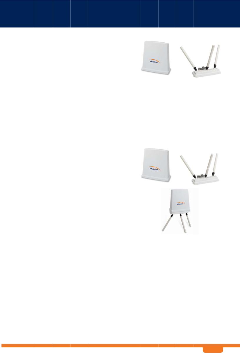
WBSn-240 0-O |
|
WBSn-2 400-O base station unit (Omni) |
||
|
|
|
|
|
PoE injec tor unit (AC or DC) |
||
|
|
|
|
|
3 antenn as |
||
|
|
|
|
Post-cla mp |
|||
|
|
|
|
Two ste el bands |
|||
|
|
|
|
2 screws, each with attached spring and flat washers |
|||
|
|
|
|
|
Steel extraction key |
||
|
|
|
|
Iron secu rity cable |
|||
|
|
|
|
|
Waterproof sealing tape for IP6 8 (tape to c over the N-Type connec tors and the |
||
|
|
|
|
|
lower pa rt of the antennas for sealing) |
||
|
|
|
|
Plastic c ap and cap cover |
|||
|
|
|
WBSn-240 0-S |
|
WBSn-2 400-S unit (Sector) |
||
|
|
|
|
|
PoE injec tor unit (AC or DC) |
||
|
|
|
|
Post-cla mp |
|||
|
|
|
|
Two ste el bands |
|||
|
|
|
|
2 screws, each with attached spring and flat washers |
|||
|
|
|
|
|
Steel extraction key |
||
|
|
|
|
Iron secu rity cable |
|||
|
|
|
|
Plastic c ap and cap cover |
|||
|
|
|
WBSn-245 0-O |
|
WBSn-2 450-O base station unit (Omni) |
||
|
|
|
WBSn-245 0-SO |
|
PoE injec tor unit (AC or DC) |
||
|
|
|
WBSn-245 0-OS |
|
3 antenn as |
||
|
|
|
|
Post-cla mp |
|||
|
|
|
|
Two ste el bands |
|||
|
|
|
|
2 screws, each with attached spring and flat washers |
|||
|
|
|
|
|
Steel extraction key |
||
|
|
|
|
Iron secu rity cable |
|||
|
|
|
|
|
Waterproof sealing tape for IP6 8 (to be bou nd around the N-type c onnector |
||
|
|
|
|
|
and ante nna base) |
||
|
|
|
|
Plastic c ap and cap cover |
|||
WB Sn-2400 a nd WBSn-2450 Us er Guide |
- 9 - |
WB Sn-2400 a nd WBSn-2450 Us er Guide
WBSn-245 0-S |
|
WBSn-2 450-S unit (Sector) |
|
|
|
PoE injec tor unit (AC |
or DC) |
|
Post-cla mp |
|
|
|
Two ste el bands |
|
|
|
2 screws, each with attached spring and flat washers |
||
|
|
Steel extraction key |
|
|
Iron secu rity cable |
|
|
|
Plastic c ap and cap cover |
||
|
The WBSn-24 50 should |
only be insta lled using t he antennas provided as part of the |
|
W arning |
original pack age. |
|
|
|
|
|
|
|
Ensure that t he USB port on the bas e station unit is properly sealed. |
||
Ad ditional e quipment and tools required for installation
Ether net cable (outdoor CAT5e 4-pair data cable, with RJ45 connectors). Note: Maximum cable lengt h -- 100 met ers
Grou nd cable, 10 AWG mini mum
Porta ble PC (for c onfiguratio n purposes)
Light ning protection – use the device recommended by Alvarion. See Lightning Protecti on.
2”-6” diameter p ole (on which to moun t the unit)
Extender (optiona l)
|
|
|
Ens |
ure a safe |
and secu |
re environ |
ment |
|
|
Co nnect the Po E injector t o the unit u sing only a straight Ethernet cable. |
|||||
|
Warning |
Do not use crossed cables between th e PoE inject or and the unit! |
|||||
|
|
||||||
|
Follow these |
|
Do not to uch or move the antennas while the unit is switched on. |
||||
|
guidelines to |
|
Make sure the antennas are connected when operating the radio or attempting |
||||
|
ensure safe |
||||||
|
operation of |
|
to transmit data, otherwise, the r adio may be damaged. |
||||
|
the WBSn - |
|
Do not hold the anten na close to or touching any exposed parts of t he body, |
||||
|
2450 base |
||||||
|
|
especially the face or eyes, while t ransmitting. |
|||||
|
station: |
|
|||||
|
|
|
|
|
|
|
|
|
|
|
The use of wireless devices on air planes is go verned by th e Federal Aviation |
||||
|
|
|
Administr ation (FAA). (US only) |
||||
|
|
|
The use of wireless devices in hazardous locat ions is limit ed to the constraints |
||||
|
|
|
posed by the safety directors of s uch environ ments. |
||||
|
|
|
The use of wireless devices in hospitals is rest ricted to the limits set fo rth by each |
||||
|
|
|
hospital. |
||||
|
|
|
Do not operate a portable transmitter near u nshielded bl asting caps or in an |
||||
|
|
|
explosive environment . |
||||
|
|
|
The Alvari on WBSn-24 50 must be used only with Alvario n-approved components |
||||
|
|
|
and antennas. |
||||
Note:
The Feder al Communications Com mission (FC C) with its action in ET Docket 96- 8 has adopted a safety standard for human exposure to RF electrom agnetic energy emitted by FCC certified equipm ent. Proper operation of the Alvarion WBSn according to the instructions found in this manu al, results in user exposure that is subst antially below the FCC r ecommended limits.
WB Sn-2400 a nd WBSn-2450 Us er Guide |
- 1 0 - |
WB Sn-2400 a nd WBSn-2450 Us er Guide
To ensure opti mal perfor mance for WBSn, select the location f or the equ ipment
 using the following guidelin es:
The antenna sho uld be direct ed towards the area intended to b e covered, w ith maximum possible lines of sight for client locatio ns. Generally speaking, the higher the placem ent of the a ntenna, the bette r the link quality achieva ble, however, the high er the installation the gr eater interf erence that the b ase station is exposed t o. Consider best installation spot that maximizes coverage and
minim izes interference.
Two meters is the minimal recommende d separation for Sector base station units (back to back).
If om ni-directional units are in use, the minimum separation is 1 0 meters.
The lo cation of th e unit should enable ea sy access fo r installatio n and testing.
When installing i n locations where other devices exist that opera te in the same frequen cy range, ensure that reco mmended distances are adhered to. For more in formation, see here.
The id eal height at which a base station should be in stalled is a minimum of 3 meters a bove the rooft ops of the buildings wit hin the coverage zone.
The omni-directio nal unit sho uld be insta lled at the h ighest point the pole. T his is to ens ure that
there is no interfe rence cause d by the clo se proximity of the antenna to other objects. |
Where this is |
not possible, the unit should be kept at least 1 meter from the p ole, using a horizontal |
bar. |
Keeping the maximum distan ce possible from an RF radiating source is recommended.

 Preparin g the insta llation sit e
Only expe rienced inst allation professionals w ho are familiar with loca l building a nd safety codes and are licensed, w herever applicable, by the appropriate govern ment regulatory authorities, should install outdoor units and antennas.
Warnings |
Importan t! This devi ce should b e installed in an area wi th restricted access. |
|
Do not m odify the c onstruction of this product. Modifying the operating frequ ency or |
|
enhancin g the trans mit output p ower through the use of external a mplifiers or other |
|
equipment is illegal. |
|
This device is for outdoor or ind oor use on the conditio n that operation of this device |
|
causes no harmful in terference to authorized radio stations. This device shall no t influence |
|
aircraft security and/or interfere with legal communications. If this d evice is found to cause |
|
interference, the operator of thi s equipment shall cease operating this device i mmediately. |
How to |
Asc ertain the ex istence of potential pos ts or poles t o which a b ase station could be |
prepare |
attached. Consider the axis of the post, its placeme nt, and wh ether extend ers are |
the site: |
requ ired. |
|
Foll ow the appropriate electrical and bu ilding codes to ensure safe and durable wiring. |
|
The total length of the Ethernet cable connecting the unit to t he network device (PC, |
|
switch, router, and so on) should not exceed 100 m eters. There is no limit ation on the |
|
leng th of the cable connecting the PoE to the unit, as long as the combined length of |
|
the cables from the network device through the Po E and to th e unit does not exceed |
|
100 meters. |
WB Sn-2400 a nd WBSn-2450 Us er Guide |
- 1 1 - |

WB Sn-2400 a nd WBSn-2450 Us er Guide
How to |
Note: Th e Grounding screw is lo cated on th e side panel of the out door unit. |
||
ground |
To conne ct the grounding cable: |
||
the WBSn |
|||
|
1. |
Conn ect one end of a grounding cable to the groun ding termin al and tighten the |
|
|
|
grou nding screw firmly. |
|
|
2. |
Rem ove the nut and star washers from the groundi ng screw. |
|
|
3. |
Attac h one star |
washer to th e groundin g screw. |
|
4. |
Attac h #10 AWG |
bare copp er wires wit h an M6 ter minal ring t o the groun ding screw. |
|
5. |
Attac h the secon d star washer and tighten the nut. |
|
|
6. |
Conn ect the other end of the grounding cable to a good ground (earth) connection, |
|
|
|
(for e xample, a g rounding ro d). |
|
Conn ecting An tennas
(for WB Sn-2400-O , WBSn-2450-O, W BSn-2450-SO, WBSn -2450-OS)
Note: The antennas s hould only b e connected once the installation p rocedure h as been suc cessfully completed and prior to powering the unit.
How to |
Screw ea ch of the th ree antenn as into the three N-type connectors on the WBS n base |
|
connect |
station unit. |
|
the |
Warnin g! Do not screw in the a ntenna wh en holding its top section or you m ay damage |
|
antennas: |
||
|
the ante nna. |
|
Warnings |
|
In order for the unit to wor k properly, a ll three ant ennas must be connect ed. |
|
|
Onl y connect the unit to th e power sup ply once all the antennas are conn ected. |
|
|
Use caution when connecti ng the ante nnas. Undue haste can damage the unit. |
WB Sn-2400 a nd WBSn-2450 Us er Guide |
- 1 2 - |

WB Sn-2400 a nd WBSn-2450 Us er Guide
Lightning Prot ection
The following procedure describe s how to correctly ensure that your de vice is protecte d against lightning.
For the best protectio n, two instances of the lightning pr otection dev ice should be used.
The recom mended device is PN: RW-9924-0006, manufactured by R ADWIN
1.Position one of th e lightning p rotection d evices as close to the bu ilding entrance as possible and conne ct it to the g rounding b ar of the building.
2. Position the second lightning protection d evice as close to the base station a s possible an d connect it to the tower/pole ground plate using a short 10 AWG cable.
3.Ensure that the tower/pole has a lightning rod conne cted to the earth with a down-cond uctor.
Note: Use only shielded CAT5 e/6 cables for the POE connection.
4.Ensure that the cable shield is firmly connected (soldered) to the RJ45 plug sh ield. Non-s hielded cables or non-shielded RJ45 plugs will not provide any grounding points or protect from static discharge or lightn ing strike
For more detailed explanation of lightning pr otection tec hniques – please refer t o the Alvari on Lightning Protection White Pape r.
Note: Lightning dam age is not covered under the Alvarion Warranty.
When corr ectly install ed, the recommendatio ns on this p age offer you the best p rotection from the harmful effects of lightning. However, 100% protection is neither im plied nor p ossible.
Lightning Protection Connectio n Diagram
|
|
|
|
|
|
|
|
|
|
|
|
|
|
|
WB Sn-2400 a nd WBSn-2450 Us er Guide |
- 1 3 - |
|||

WB Sn-2400 a nd WBSn-2450 Us er Guide
An tenna Se aling
The following procedure describe s how to correctly seal the antennas a gainst moisture . 
Caution |
|
It is important t o carefully r ead this procedure and perform all the steps, to ensure |
||
|
|
maximal moisture protection. |
||
|
|
Use high quality sealing material to ensure IP-68 co mpliant protection against dust an d |
||
|
|
water. |
|
|
How to |
1. After the antenna is connected, use the supplied |
|||
seal the |
||||
|
isolation tape to cover the N-Type conne ctors and t he |
|||
antennas: |
|
|||
|
|
lower part of the antennas. |
||
|
2. |
Cut 1 8 cm of the |
attached splicing tape. |
|
|
3. |
Stret ch and wrap |
the tape in an even, h alf overlapping |
|
|
|
man ner around t he antenna and N-Type connector. |
||
|
|
Cover this with a layer of vinyl plastic ta pe. |
||
Safety instr uctions and informa tion
Pleas e ensure that you r ead and understand the foll owing safety infor mation. Ensure that you c arefully re ad and fo llow all i nstructions in this m anual, an d heed all
warning s.
Warnings It is illega l to modify the construction of this product. M odifying th e operating frequency or enhancin g the trans mit output p ower through the use of external a mplifiers or other equipment is specific ally disallow ed by the "Telecommu nications A ct”.
There is a risk of personal injury or death if t he WBSn a ntennas are close to ele ctric power lines.
By natur e of the outdoor installa tion, you may be exposed to hazardous enviro nments and high voltage. Use extreme cauti on when installing the system.
Servicing is required when the apparatus has been damaged in any way. All servicing should be referred t o qualified service personnel only.
The base station must be properly grounded .
Do not open the unit – risk of electric shock.
Any cha nge or modification not expressly d escribed in this manual or approved by the manufacturer could void your au thority to operate this equipment.
WBSn should only b e installed using the antennas that were provided as part of the original package.
A minimum distance of 40cm sh ould be kep t from the WBSn anten na when the system is in operat ion.
To maintain Overvol tage (Install ation) Category II, install a suitable s urge suppr essor device in the branch circuit to limit exp ected transi ents to Overvoltage Category II values. The limits are based on I EC60664 and are also l ocated in Table 2H of U L60950 (for mains 110V, the transient r ating is 150 0V).
WB Sn-2400 a nd WBSn-2450 Us er Guide |
- 1 4 - |

WB Sn-2400 a nd WBSn-2450 User Guide
2. 2 |
Installation a nd Set-up |
|
The following section describes the installa tion and configuratio n procedures for the WBSn base |
|
station. |
2.2.1 |
Pre-Installatio n – Con necting to the Data Po rt |
The following describes how to apply power and data to the WBSn.
Prior to connecting power to the WBSn, e nsure that you have read and performed all instructio ns in the pre-installation checklist.
The Alvarion WBSn is equipped with two ports.
Use the ETH port to conne ct the PoE cable.
The U SB port is for engineering purposes only. Ensure that the USB port is properly sealed with a plastic cap.
Please also note the following:
|
You must always install an external groundin g wire. Ma ke sure you have completed |
|
grounding before yo u connect power to the WBSn unit. |
Warnings |
This is not a mid-span powered d evice. Do not attempt to daisy-chain PoE devices. |
|
|
Note: |
National Electrical Codes (NEC) A rticle 800 requires the use of an Ag ency Listed |
|
(UL/CSA) Building Entrance Protector for all power and communications cables |
|
entering a building. Article 800 is intended to protect the building and occupants |
|
from fires caused by transient voltage and cu rrent surges. |
|
|
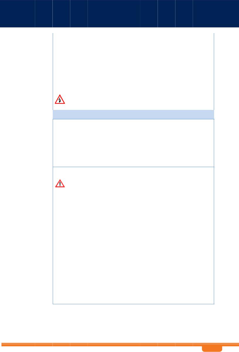
Important Note: The gland base is attach ed to the WBSn unit and should not under any circu mstances be fully removed.
1.Ensure that the power is turned off for the designated circuits.
2.Twist the nut using a steel extracti on key, or an equivalent tool, to give yourself access to the inner sle eve.
WB Sn-2400 a nd WBSn-2450 User Guide |
- 15 - |
WB Sn-2400 a nd WBSn-2450 Us er Guide
3.Remove th e rubber bushing (inner sleeve) from the body o f the gland.
4.Feed the sh ielded Category 5 Ethe rnet cable (a ppropriate for outdoor use) throug h the released nut and the rubber bushing.
Note: Use a shielded RJ45 8-pin modular plug to terminate the cables at th e required length.
5.Crimp the cable and assemble the appropriate connector.
6. Connect the cable to t he outdoor unit.
7.Push the rubber bushin g firmly bac k into place inside the body of the gland.
8.Close the nut and tight en firmly, using a steel extraction key, or an equivalent tool, to ens ure perfect sealing and IP-68 compliance.
9.Connect the other end of the Category 5 cabl e to the OU T port of the PoE injecto r.
10.Connect on e end of the network source cable to the IN p ort on the P oE injector, and the oth er end to the network.
Note: The DC PoE image may diff er in appear ance. For more information, refer t o the docum entation in cluded with the DC PoE package.
11.Connect the other end of the Category 5 Ethernet cable t o the ETH port on the A lvarion WBSn.
Note: Use a shielded RJ45 8-pin modular plug to terminate the cables at the requ ired length.
12.Close and firmly tighten the plastic cap, to ensure perfect sealing and IP-68 compliance. Con nect the network cable to the IN port of the P oE injector.
Note: The above proce dure must be conducted after every disconnection of the E thernet cab le from either ETH port on the WBSn unit or from the OUT port of the PoE in jector.
WB Sn-2400 a nd WBSn-2450 Us er Guide |
- 1 6 - |

WB Sn-2400 a nd WBSn-2450 User Guide
Note: The Alvarion PoE provides power over 1Gbps Ether net, meaning that there are no spare wires. All wires are used for power and data concurre ntly.
Important: If you have an A/C MST PoE Injector, please refer to Appendix D.
|
POE port RJ45 Pin Descriptio ns |
|
|
|
|
|||
|
|
Pin |
Signal |
|
Color |
|
Description |
|
|
1 |
BI_D A+ |
|
OrangeWhite |
Bi-directional pair A +, POE GND |
|||
|
2 |
BI_D A- |
|
Orange |
Bi-directional pair A -, POE GND |
|||
|
3 |
BI_D B+ |
|
Green-White |
Bi-directional pair B +, POE +55V |
|||
|
4 |
BI_D C+ |
|
Blue |
Bi-directional pair C +, POE +55V |
|||
|
5 |
BI_D C- |
|
Blue-White |
Bi-directional pair C -, POE +55V |
|||
|
6 |
BI_D B- |
|
Green |
Bi-directional pair B -, POE + 55V |
|||
|
7 |
BI_D D+ |
|
Brown-W hite |
Bi-directional pair D +, POE GND |
|||
|
8 |
BI_D D- |
|
Brown |
Bi-directional pair D -, POE GND |
|||
2.2.2 |
Installi ng the WBSn base station |
|
|
|
||||
Prior to performing t he procedures describ ed in this section, ensure that you have read all the information, and foll owed all instructions and safety precautions in the Pr e-Installatio n Checklist.
To install WBSn:
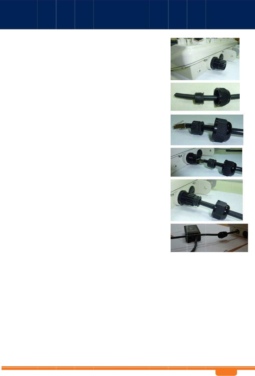
1. Slide the steel bands into th e appropriate side slots of the p ost clamp.
Mounting Kit Post Clamp (pl us half-extender*)
* Half exten der not included in shipment
Note: For a thinner post, the steel bands should b e threaded through t he inner slots, and for a wider po st, through the oute r slots.
2. Attach the post-c lamp to th e post, and close and tighten th e steel ba nds, with torque of 3.8 lbft (5.1 Nm).
3.If you are installing WBSn on a horizo ntal post, select the direction in which the base station unit sh ould point on the horizontal plane prior to continuing with the installatio n. Once you have determined the correct direction, connect the extende r to the po st clamp, and procee d to Step 5.
Note: The extender must be specified as an extra item when ord ering the W BSn unit.
WB Sn-2400 a nd WBSn-2450 User Guide |
- 17 - |
WB Sn-2400 a nd WBSn-2450 User Guide
4. If you are installing the WB Sn on a vertical post, attach the WBSn unit to the post-clamp, w ith the screws and w ashers. Tighten the screws using a 13mm ratchet key with torq ue of 18.4 lbft (25 Nm).
N ote: If you are installing either a Sector, Sector-Omni, or O mni-Sector WBSn unit, see Mounting.
H orizontally mounted WBSn attached with exte nder
5. Attach the WBSn base station unit (and connect ed extender) to the b ase station unit.
6.Tighten the bolts with torq ue of 18.4 lb-ft (25 Nm). As you tighten the screws, verify that the tilt and direction of the base station unit are correct for the coverage area required.
Note: In an urban setting, with a high-placed installation, a slight downwards tilt (approximately 8-10 degrees) will help reduce noise and interference.
7.Thread the iron cable through the corner hole on the post-clamp, and the middle hole on the WBSn unit, securing it with the Caribe na provide d. This will provide extra physical security for the unit..
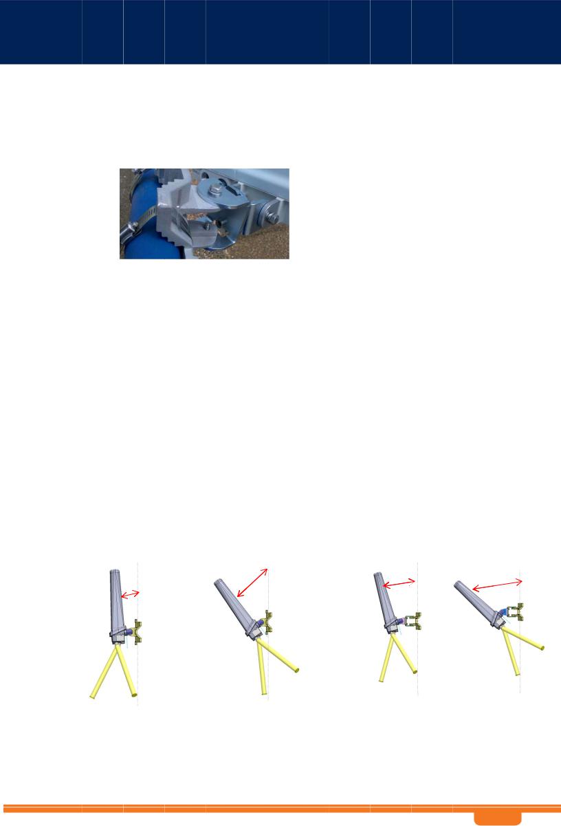
2.2.3 Mounting
Sector, Sec tor-Omni and Omni-Sector units support both pole a nd wall mounting, as shown in the following illustration. For best performance for a Sector unit, the recomm endation is to install using a horizont al mount, a s it offers a wider ra nge of directional adj ustment.
The following illustration shows sector-omni (or omni-sector) u nits, howev er this issue also applies to Sector u nits.
|
Max downwards tilt without e xtender |
Max downwards tilt with extend er |
|||||
Wall mount |
Pole mount |
Wall mou nt |
Pole m ount |
||||
|
|
|
|
15º |
|
|
|
|
|
|
36º |
|
|
|
|
|
3º |
|
|
|
|
||
|
|
|
|
43º |
|||
|
|
|
|
|
|
|
|
|
|
|
|
|
|
|
|
|
|
|
|
|
|
|
|
2.2.4 Connecting an d Sealing anten nas
If you are installing a WBSn unit with external antennas, you should conn ect and sea l your antennas a t this point, prior to connecting the WBSn unit to a power source. For inf ormation about these procedures, see the sections Connecting Anten nas and S ealing the Antennas.
WB Sn-2400 a nd WBSn-2450 User Guide |
- 18 - |
WB Sn-2400 a nd WBSn-2450 Us er Guide
2. 3 Wind L oadin g Considerations
The Alvario n WBSn w eighs app roximately eight kilograms, inclu ding all mounting hardware, with minor diffe rences according to model. When the Alvarion WBS n is mounted on a pole, the sail area of the WB Sn is approximately 0.11 m2. Th e Alvarion WBSn can load a pole with a m aximum lo ad of 3400 Newton in win d condition s of 264 km/h (165 mph).
You sho uld evaluate the static and dynamic load bearing capabilities for each assembly and installati on individually.
2. 4 Access ing the Alva ion M anage ment I nterfac e
The following procedure describ es how to log in to the WBSn Entity Mana gement S ystem (EMS) interface, and from t here enter the Set-up Wizard, a nd further configuration inform ation.
Note: The WBSn inte rface requires that yo u have the latest ver sion of Jav a Runtime Environment installed o n your PC.
1.In an internet bro wser, ente r the Management IP address of the WBS n unit in the URL navigation field.
2.Note: The default IP address of the un it is IP: http://192.168.1.1. Currently, Microsoft Internet Explorer, Chrome and Mozilla Firefox browsers are supported.
3.A log-in screen is displayed.
En ter admin in the Use r Name fie ld.
En ter admin in the password fiel d.
Sp ecify the l anguage in which yo u wish to w ork. (Not e: This field will be fu nctional in a future release of WBSn.)
4.Click C onnect. The Alvario n EMS screen is displa yed.
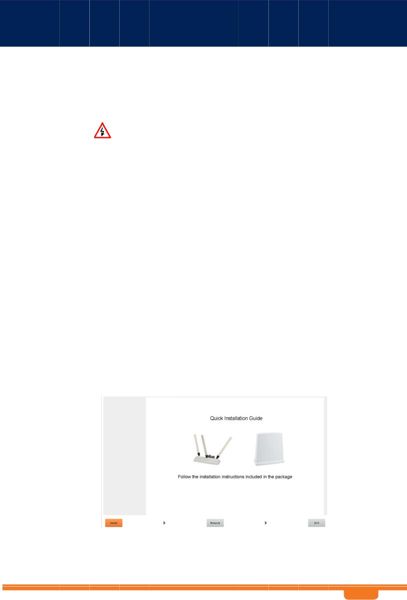
5.Select the Setup Wizard option.
6.The Installation screen is d isplayed. C lick the arrow in the bottom rig ht corner of the scre en to procee d to the Network Configuration screen.
WB Sn-2400 a nd WBSn-2450 Us er Guide |
- 1 9 - |

WB Sn-2400 a nd WBSn-2450 Us er Guide
7.Complete the parameters, t o set up y our initial n etworking configuration.
Note: Further configuration parameters are available, and should be s pecified in order to complete your set-up. For m ore inform ation, see the section entitled Configuration.
|
Parameter |
Descr |
iption an |
d value |
|
IP address |
The current IP address of the unit |
||
|
Mask |
The current subnet mask used to establish the broadcast domain. Th e default |
||
|
|
mask of the unit is 25 5.255.255.0. |
||
|
Gatew ay |
The current IP address of the def ault gateway. |
||
|
IP Method |
Select Manual or DH CP |
||
|
VAP Name |
The defau lt VAP name string to b e used as th e SSID string |
||
|
Securi ty mode |
Specify the required Wi-Fi security protocol f or the VAP |
||
2. 5 Autom atic C hannel Selec ion screen
The Autom atic Chan nel Selectio n utilizes a n embedded algorith m to scan for the be st channel with which you r base station can work, ensuring minimal interferenc e, optimal capacity, a nd maximum performance.
Note: You can only scan for one band at a time. To scan for bo th the 2.4 and 5 GH z bands, yo u need to re peat the pr ocess.
1.Click P ress to start ACS scan. The scan begins, and a pro gress indicator is displayed, sho wing the percentage of completi on.
2.When the scan is complete (after approximately five minute s), the button label changes to ACS done.
3.Naviga te to Stat us => Radio => ACS Results t o see the results. Sep arate tabbe d pages ar e
display ed for both the 2.4 GHz band, as well as the 5 GHz band. 4. You ar e requested to exit th e Setup Wizard, by clicking E xit.
WB Sn-2400 a nd WBSn-2450 Us er Guide |
- 2 0 - |
WB Sn-2400 a nd WBSn-2450 User Guide
3 WBSn Set up and Manageme nt
The WBSn EMS interface is comprised of three separate sections, that each relate to the key ar eas
that you will use.
The Status secti on enables you to check how the system is working, and whether the unit is configured correctly.
The C onfiguration section enables y ou to configure the unit’s wireless and Ethernet specifications according to your requirements.
The Administration section enables comprehen sive maintenance of the unit fr om the user’s point of view, in cluding spe cifying logs to be created, and creating an d adding new users to the system.
3. 1 |
Status |
|
|
|
|
|||
|
This section enables y ou to chec k how you r system is working, and whether the WB Sn unit and |
|||||||
|
software/firmware are configur ed correctly. |
|||||||
|
There are 4 sections: |
|
|
|
|
|||
|
Device indicates Uptime ( duration of time from last power up), Date (yyyy/mm/dd) and Time |
|||||||
|
|
|
Zone (Default: G MT) |
|||||
|
Network indicates Network Mode (Default: Bridge) |
|||||||
|
Wirel ess Parameters indic ates table of current VAPs |
|||||||
|
Interfaces displa ys the Wireless and E thernet tables |
|||||||
|
|
|
Para |
meter |
|
Description an |
d values |
|
|
|
|
Device |
Indicates the time duration since last power-up displayed in the Uptime field. |
|
|||
|
|
|
|
|
Date field: current date |
|
||
|
|
|
|
|
Time Zone: selected time zone (G MT +/- valu e) |
|
||
|
|
|
Network |
Displays the current Network Mode (Default: Bridge). |
|
|||
|
|
|
Wireless Parameters |
Displays the information table about current VAPs (Security Mode, H idden SSID, |
|
|||
|
|
|
|
|
Band, # of Associations). |
|
||
|
|
|
|
|
Note: Below this table, the Total Associations parameter is displayed. |
|
||
|
|
|
Interfaces |
Wireless Table displays informati on regardin g wireless drivers (Wi-Fi Driver, |
|
|||
|
|
|
|
|
MAC Address, Radio Status, Freq uency, Channel, Chann el Width); |
|
||
|
|
|
|
|
Ethernet Table displays information regarding Name, MAC Address, Link, |
|
||
|
|
|
|
|
Speed, D uplex, and N egotiation. |
|
||
3.1.1 |
Checkin g Syste m Setup |
|||||||
Navigate t o Status => System for an overall view of the system settings.
|
Para |
meter |
|
Description and values |
|
|
Time |
Indicates the unified time of the unit, according to the NTP server, and your |
|||
|
|
|
specific time zone. |
||
|
Software Versions |
Displays the current (and previous or alternative, where applicable) firmware |
|||
|
|
|
version. For more inf ormation, se e the Firmw are section. |
||
|
Resource Utilization |
Indicates the resourc es utilized by the system |
|||
|
Country Code |
Displays the current c ountry code according to the regulatory domain of which |
|||
|
|
|
your base station is s et to operate. |
||
WB Sn-2400 a nd WBSn-2450 User Guide |
- 21 - |
 Loading...