


BreezeNET DS.11 Series
BU-DS.11
RB-DS.11
User Manual
January 2005
S/W Version 4.2
P/N: 213993

ii
BreezeNET DS.11 Series User Manual

Important Notice
© Copyright Alvarion Ltd (“Alvarion”). All rights reserved.
The material contained herein is proprietary, privileged, and confidential. No
disclosure thereof shall be made to third parties without the express written
permission of Alvarion.
Alvarion reserves the right to alter the equipment specifications and descriptions in
this publication without prior notice. No part of this publication shall be deemed to
be part of any contract or warranty unless specifically incorporated by reference
into such contract or warranty.
Trade Names
Alvarion, BreezeCOM, WALKair, WALKnet, BreezeNET, BreezeMANAGE,
BreezeACCESS, BreezeMAX, AlvariSTAR, MGW, eMGW and/or other products
and/or services referenced here in are either registered trademarks, trademarks or
service marks of Alvarion. All other names are or may be the trademarks of their
respective owners.
iii
Statement of Conditions
The information contained in this manual is subject to change without notice.
Alvarion shall not be liable for errors contained herein or for incidental or
consequential damages in connection with the furnishing, performance, or use of
this manual or equipment supplied with it.
Warranties; Disclaimers
All Alvarion products purchased from Alvarion or through any of Alvarion’s
authorized resellers are subject to the following warranty and product liability
terms and conditions.
Exclusive Warranty
Alvarion warrants that the Product hardware it supplies and the tangible media on
which any software is installed, under normal use and conditions, will be free from
significant defects in materials and workmanship for a period of fourteen (14)
months from the date of shipment of a given Product to Purchaser (the “Warranty
Period”). Alvarion will, at its sole option and as Purchaser’s sole remedy, repair or
replace any defective Product in accordance with Alvarion’ standard RMA
procedure.

iv
BreezeNET DS.11 Series User Manual
Disclaimer
(a) UNITS OF PRODUCT (INCLUDING ALL THE SOFTWARE) DELIVERED TO
PURCHASER HEREUNDER ARE NOT FAULT-TOLERANT AND ARE NOT
DESIGNED, MANUFACTURED OR INTENDED FOR USE OR RESALE IN
APPLICATIONS WHERE THE FAILURE, MALFUNCTION OR INACCURACY OF
PRODUCTS CARRIES A RISK OF DEATH OR BODILY INJURY OR SEVERE
PHYSICAL OR ENVIRONMENTAL DAMAGE (“HIGH RISK ACTIVITIES”). HIGH RISK
ACTIVITIES MAY INCLUDE, BUT ARE NOT LIMITED TO, USE AS PART OF
ON-LINE CONTROL SYSTEMS IN HAZARDOUS ENVIRONMENTS REQUIRING
FAIL-SAFE PERFORMANCE, SUCH AS IN THE OPERATION OF NUCLEAR
FACILITIES, AIRCRAFT NAVIGATION OR COMMUNICATION SYSTEMS, AIR
TRAFFIC CONTROL, LIFE SUPPORT MACHINES, WEAPONS SYSTEMS OR OTHER
APPLICATIONS REPRESENTING A SIMILAR DEGREE OF POTENTIAL HAZARD.
ALVARION SPECIFICALLY DISCLAIMS ANY EXPRESS OR IMPLIED WARRANTY OF
FITNESS FOR HIGH RISK ACTIVITIES.
(b) PURCHASER’S SOLE REMEDY FOR BREACH OF THE EXPRESS WARRANTIES
ABOVE SHALL BE REPLACEMENT OR REFUND OF THE PURCHASE PRICE AS
SPECIFIED ABOVE, AT ALVARION’S OPTION. TO THE FULLEST EXTENT
ALLOWED BY LAW, THE WARRANTIES AND REMEDIES SET FORTH IN THIS
AGREEMENT ARE EXCLUSIVE AND IN LIEU OF ALL OTHER WARRANTIES OR
CONDITIONS, EXPRESS OR IMPLIED, EITHER IN FACT OR BY OPERATION OF
LAW, STATUTORY OR OTHERWISE, INCLUDING BUT NOT LIMITED TO
WARRANTIES, TERMS OR CONDITIONS OF MERCHANTABILITY, FITNESS FOR A
PARTICULAR PURPOSE, SATISFACTORY QUALITY, CORRESPONDENCE WITH
DESCRIPTION, NON-INFRINGEMENT, AND ACCURACY OF INFORMATION
GENERATED. ALL OF WHICH ARE EXPRESSLY DISCLAIMED. ALVARION’
WARRANTIES HEREIN RUN ONLY TO PURCHASER, AND ARE NOT EXTENDED
TO ANY THIRD PARTIES. ALVARION NEITHER ASSUMES NOR AUTHORIZES ANY
OTHER PERSON TO ASSUME FOR IT ANY OTHER LIABILITY IN CONNECTION
WITH THE SALE, INSTALLATION, MAINTENANCE OR USE OF ITS PRODUCTS.
(c) ALVARION SHALL NOT BE LIABLE UNDER THIS WARRANTY IF ITS TESTING
AND EXAMINATION DISCLOSE THAT THE ALLEGED DEFECT IN THE PRODUCT
DOES NOT EXIST OR WAS CAUSED BY PURCHASER’S OR ANY THIRD PERSON'S
MISUSE, NEGLIGENCE, IMPROPER INSTALLATION OR IMPROPER TESTING,
UNAUTHORIZED ATTEMPTS TO REPAIR, OR ANY OTHER CAUSE BEYOND THE
RANGE OF THE INTENDED USE, OR BY ACCIDENT, FIRE, LIGHTNING OR
OTHER HAZARD.

Important Notice
Limitation of Liability
(a) ALVARION SHALL NOT BE LIABLE TO THE PURCHASER OR TO ANY THIRD
PARTY, FOR ANY LOSS OF PROFITS, LOSS OF USE, INTERRUPTION OF
BUSINESS OR FOR ANY INDIRECT, SPECIAL, INCIDENTAL, PUNITIVE OR
CONSEQUENTIAL DAMAGES OF ANY KIND, WHETHER ARISING UNDER
BREACH OF CONTRACT, TORT (INCLUDING NEGLIGENCE), STRICT LIABILITY
OR OTHERWISE AND WHETHER BASED ON THIS AGREEMENT OR OTHERWISE,
EVEN IF ADVISED OF THE POSSIBILITY OF SUCH DAMAGES.
(b) TO THE EXTENT PERMITTED BY APPLICABLE LAW, IN NO EVENT SHALL THE
LIABILITY FOR DAMAGES HEREUNDER OF ALVARION OR ITS EMPLOYEES OR
AGENTS EXCEED THE PURCHASE PRICE PAID FOR THE PRODUCT BY
PURCHASER, NOR SHALL THE AGGREGATE LIABILITY FOR DAMAGES TO ALL
PARTIES REGARDING ANY PRODUCT EXCEED THE PURCHASE PRICE PAID FOR
THAT PRODUCT BY THAT PARTY (EXCEPT IN THE CASE OF A BREACH OF A
PARTY’S CONFIDENTIALITY OBLIGATIONS).
v
Electronic Emission Notices
This device complies with Part 15 of the FCC rules, ETSI 300-328 and CE.
Operation is subject to the following two conditions:
1. This device may not cause harmful interference.
2. This device must accept any interference received, including interference that
may cause undesired operation.
FCC Radio Frequency Interference Statement
This equipment has been tested and found to comply with the limits for a Class B
digital device, pursuant to part 15 of the FCC Rules. These limits are designed to
provide reasonable protection against harmful interference when the equipment is
operated in a residential environment, not withstanding use in commercial,
business and industrial environments. This equipment generates, uses and can
radiate radio frequency energy and, if not installed and used in accordance with
the instructions, may cause harmful interference to radio communications.
However, there is no guarantee that interference will not occur in a particular
installation.
If this equipment does cause harmful interference to radio or television reception,
which can be determined by turning the equipment off and on, the user is
encouraged to try to correct the interference by one or more of the following
measures:
• Reorient or relocate the receiving antenna.
• Increase the separation between the equipment and receiver.
• Connect the equipment into an outlet on a circuit different from that to which
the receiver is connected.

vi
BreezeNET DS.11 Series User Manual
• Consult the dealer or an experienced radio/TV technician for help
Changes or modifications to this equipment not expressly approved by the party
responsible for compliance could void the user’s authority to operate the
equipment.
FCC Radiation Exposure Statement
To comply with FCC RF exposure requirements in section 1.1307, a minimum
separation distance of 2 m (79 inches) is required between the antenna and all
persons.
Antenna Installation
WARNING: It is the responsibility of the installer to insure that when using the
outdoor antenna kits in the United States (or where FCC rules apply), only those
antennas certified with the product are used. The use of any antenna other than
those certified with the product is expressly forbidden in accordance to FCC rules
CFR47 part 15.204.
The installer should configure the output power level of antennas, according to
country regulations and per antenna type.

Important Notice
Important Notice
This manual is applicable to BreezeNET DS.11 units and is delivered subject to the
following conditions and restrictions:
♦ This manual contains proprietary information belonging to Alvarion. Such
information is supplied solely for the purpose of assisting explicitly and
properly authorized users of BreezeNET DS.11 equipment.
♦ No part of its contents may be used for any other purpose, disclosed to any
person or firm or reproduced by any means, electronic and mechanical,
without the express prior written permission of Alvarion.
♦ The text and graphics are for the purpose of illustration and reference only. The
specifications on which they are based are subject to change without notice.
♦ The software described in this document is furnished under a license. The
software may be used or copied only in accordance with the terms of that
license.
vii
♦ Information in this document is subject to change without notice.
♦ Corporate and individual names and data used in examples herein are
fictitious unless otherwise noted.
♦ Alvarion reserves the right to alter the equipment specifications and
descriptions in this publication without prior notice. No part of this publication
shall be deemed to be part of any contract or warranty unless specifically
incorporated by reference into such contract or warranty.
♦ The information contained herein is merely descriptive in nature, and does not
constitute a binding offer for the sale of the product described herein.
♦ Any changes or modifications of equipment, including opening of the
equipment not expressly approved by Alvarion will void equipment warranty
and any repair thereafter shall be charged for. It could also void the user’s
authority to operate the equipment.
♦ Some of the equipment provided by Alvarion and specified in this manual, is
manufactured and warranted by third parties. All such equipment must be
installed and handled in full compliance with the instructions provided by such
manufacturers as attached to this manual or provided thereafter by Alvarion or
the manufacturers. Non-compliance with such instructions may result in
serious damage and/or bodily harm and/or void the user’s authority to operate
the equipment and/or revoke the warranty provided by such manufacturer.

viii
BreezeNET DS.11 Series User Manual
Contacting Alvarion Technical
Support
Should you need assistance beyond the scope of this manual, please contact your
local Alvarion reseller or distributor. If they cannot solve your problem, feel free to
contact the Alvarion Technical Support Department. The support representative
can assist you in solving any problems that cannot be solved by your reseller.
When requesting support, please have the following items available:
♦ Configuration of the system, including models of the Alvarion equipment used
and other applicable equipment and connecting cables
♦ Hardware and Firmware versions of the Alvarion equipment
♦ Configuration and statistics counters as viewed in the Configuration Utility
♦ Description of the problem encountered
To contact Alvarion Technical Support Department, refer to the Alvarion web site:
www.alvarion.com/support.htm

Table of Contents
ix
User Manual
Table of Contents
Introduction 1-1
Scope of the Manual 1-2
System Description 1-3
Functional Description 1-3
BreezeNET DS.11 Compatibility and Standards 1-4
Installation 2-1
Packing List 2-2
Additional Installation Requirements 2-2
Installation Overview 2-3
Outdoor Installation Considerations 2-5
Collocating DS.11 Outdoor Units 2-5
Site Selection Factors 2-5
Rooftop Installation 2-6
Antennas for Outdoor Applications 2-6
Antenna Polarization 2-6
Antenna Seal 2-7
Cell Size/Link Distance 2-7
Using Outdoor Range Tables 2-7
Available Antennas 2-7
Precautions 2-8
Compliance with Radio Regulations 2-8
Installing the Outdoor Unit 2-9
Connecting the Ground and Antenna Cables 2-11
Connecting the Indoor-to-Outdoor Cable 2-11
Installing the Indoor Unit 2-13
Configuring Parameters 2-14
Antenna Alignment 2-14
Verifying Correct Operation 2-15
Verifying Correct Operation of the Indoor Unit 2-15
Verifying Correct Operation of the Outdoor Unit 2-15

x
What to do if the Self Test Fails 2-16
BreezeNET DS.11 Series User Manual
The DS.11 Configuration Utility 3-1
Installing and Accessing the Configuration Utility 3-2
Configuration Utility Modes 3-2
Unit Configuration Mode 3-3
Firmware Upgrade Mode 3-28
Multiple Unit Configuration Mode 3-30
Resetting the SNMP Community Strings 3-31
Reloading Factory Default Settings 3-31
Configuration Guidelines 4-1
Configuring Critical Parameters 4-2
One-Click Configuration 4-2
Short Preamble 4-2
CW Minimum 4-2
RTS Threshold 4-3
Basic Rate 4-3
Range 4-3
System Troubleshooting 5-1
Troubleshooting Guide 5-2
Technical Specifications 6-1
DS.11 FAQ A-1
General A-2
Collocation and Interference A-4
Firmware A-5
Configuration A-6
Accessories A-7
Management A-8
Preparing the Indoor to Outdoor Cable 1
Radio Signal Propagation 1
RF Terms and Definitions 1

Table of Contents
xi
Table of Figures
Figure 1-1: BreezeNET DS.11 Point-to-Multipoint Application 1-3
Figure 2-1: General Installation Scheme - Pole Mounting 2-4
Figure 2-2: Installation Holes/Grooves 2-9
Figure 2-3: 3” Pole Mounting Installation Using the Supplied Brackets 2-10
Figure 2-4: Outdoor Unit Bottom Panel (shown without the service box) 2-11
Figure 2-5: The Waterproof Service Box 2-12
Figure 2-6: Indoor Unit Top Panel 2-13
Figure 3-1: DS.11 Configuration Utility Main Window (Station Control Tab) 3-3
Figure 3-2: The Set IP Dialog Box 3-4
Figure 3-3: Station Status Tab (BU-DS.11) 3-5
Figure 3-4: Networking Parameters Tab (BU) 3-6
Figure 3-5: Networking Parameters Tab (BU) 3-9
Figure 3-6: SNMP Parameters Tab 3-11
Figure 3-7: Counters Tab (BU Units) 3-12
Figure 3-8: WLAN Parameters Tab (BU Units) 3-14
Figure 3-9: WLAN Parameters Tab (RB Units) 3-14
Figure 3-10: The Station Control Tab 3-17
Figure 3-11: Encryption Tab 3-18
Figure 3-12: ACL Table Tab 3-20
Figure 3-13: Advanced Tab 3-21
Figure 3-14: General Parameters Tab (BU) 3-23
Figure 3-15: General Parameters Tab (RB) 3-23
Figure 3-16: Auto-Config Tab 3-26
Figure 3-17: Trap Monitor Tab 3-27
Figure 3-18: Firmware Upgrade Mode dialog box 3-28
Figure 3-19: Firmware Upgrade Process 3-29
Figure 3-20: Advanced TFTP Setup 3-29
Figure 3-21: Multiple Configuration Mode 3-30

xii
BreezeNET DS.11 Series User Manual
Table of Tables
Table 2-1: Available Antennas .............................................................................................2-7
Table 2-2: Indoor Unit LEDs .............................................................................................. 2-15
Table 2-3: Outdoor Unit LEDs ........................................................................................... 2-16
Table 3-1: Regulatory Domains Specifications ...................................................................3-16
Table 3-2: Frequency List .................................................................................................. 3-16

Introduction
Chapter 1
About This Chapter
This chapter is comprised of the following sections:
♦ Scope of the Manual, page 1-2, describes the chapters and topics comprising
the BreezeNET DS.11 Series User Manual.
♦ System Description, page 1-3, provides an overview of the DS.11 system and
introduces the system components.
1-1

1-2
Scope of the Manual
This manual provides instructions for planning and setting up a wireless link
based on the BreezeNET DS.11 wireless Base Unit and Remote Bridge.
♦ Chapter 1: Introduction - Describes how to use this manual and presents the
BreezeNET DS.11 series.
♦ Chapter 2: Installation - Describes how to install the BreezeNET DS.11 units.
♦ Chapter 3: The DS.11 Configuration Utility - Describes how to use the
DS.11 Configuration Utility to setup, configure, and manage BreezeNET DS.11
units.
♦ Chapter 4: Configuration Guidelines – Provides guidelines regarding
configuration of parameters that are critical for achieving good performance.
♦ Chapter 5: System Troubleshooting - Solves some of the more common
problems which may occur when installing and using the BreezeNET DS.11
units.
BreezeNET DS.11 Series User Manual
♦ Chapter 6: Technical Specifications - Lists the technical specifications of the
BreezeNET DS.11 units.
♦ Appendix A: DS.11 FAQ- Answers questions frequently asked by customers.
♦ Appendix B: Preparing the Indoor-to-outdoor Cable - Explains how to
prepare and install the cable connecting the indoor to the outdoor unit.
♦ Appendix C: Radio Signal Propagation - Describes many of the terms and
concepts related to antennas and RF (Radio Frequency) systems.

Introduction
System Description
The BreezeNET DS.11 wireless Base Unit (BU-DS.11) and Remote Bridge (RB-
DS.11) are designed to provide long-range point-to-multipoint links for outdoor
applications. The products use direct sequence spread spectrum radio technology
operating at the frequency range of 2.4 – 2.4835 GHz, a part of the FCC's
unlicensed Industrial, Scientific and Medical (ISM) band. Data is transmitted at
rates of up to 11 Mbps, providing network users with full 10BaseT Ethernet
speeds.
Functional Description
The BreezeNET BU-DS.11 and RB-DS.11 can be used as high-speed connections
between two or more remote networks.
File
Server
Mail
Server
1-3
Central Network
BU-DS.11
Base Unit
Figure
RB-DS.11
1
Remote Network 1
1-1: BreezeNET DS.11 Point-to-Multipoint Application
RB-DS.11
2
ServerServer
Remote Network 2
RB-DS.11
3
Server
Remote Network 3
BU-DS.11 Wireless Base Unit
The BU-DS.11 is an IEEE 802.11b compliant base station that connects one or
more remote sites to a central server or Internet connection. In a point-to-multi-
point configuration the BU-DS.11 is the central unit while in point-to-point
configurations it should be installed at one end of the link.
The BU-DS.11 is available in two options: The BU-DS.11 and the BU-DS.11D.
The BU-DS.11 is the basic unit, equipped with an antenna integrated into the front
cover of the outdoor unit.
The BU-DS.11D doesn’t have an integral antenna and is equipped with a connector
(on the outdoor unit) for an external antenna (not included with the unit).
Refer to Antennas for Outdoor Applications on page 2-6 and Available Antennas on
page 2-7 for information on how to select an appropriate external antenna.

1-4
BreezeNET DS.11 Series User Manual
RB-DS.11 Wireless Bridge
The RB-DS.11 Wireless Bridge connects a remote Ethernet network to a central
network server or Internet site via a BU-DS.11 Multipoint Base Unit.
The maximum number of MAC addresses that the unit can handle at any specific
time is 1024 and the Aging algorithm is applied at all times.
When a station on the Ethernet LAN sends a message that is not destined for a
local station, the RB-DS.11 forwards the message to the BU-DS.11. When the
BU-DS.11 receives a message destined for a station on the RB-DS.11's LAN, the
BU-DS.11 forwards it to the RB-DS.11. In this manner, the RB-DS.11 and the
BU-DS.11 work together like a standard network bridge.
The first time each station on the RB-DS.11’s LAN sends a message, the station’s
address is registered by both the RB-DS.11 and the BU-DS.11. It is possible for the
RB-DS.11 and BU-DS.11 to store all the addresses necessary to support an entire
LAN connected to a RB-DS.11.
The RB-DS.11 comes in two options: The RB-DS.11 and the RB-DS.11D.
The RB-DS.11 is the basic unit, equipped with an antenna integrated into the front
cover of the outdoor unit.
The RB-DS.11D has no integral antenna and is equipped with an antenna
connector (on the outdoor unit) for the connection of an external antenna (not
included with the unit).
Refer to Antennas for Outdoor Applications on page 2-6 and Available Antennas on
page 2-7 for information on how to select an external antenna.
BreezeNET DS.11 Compatibility and Standards
BreezeNET DS.11 products are compatible with the following standards and are
interoperable with other IEEE 802.11b compatible, 2.4 GHz direct sequence
products.
♦ IEEE 802.11b Wireless LAN.
♦ IEEE 802.3 10BaseT Ethernet.
♦ DHCP for automatic IP address assignment.
♦ SNMP for system management.

Installation
Chapter 2
About This Chapter
This chapter is comprised of the following sections:
♦ Packing List, page 2-2, describes the components included with the
BreezeNET DS.11 series installation kit.
♦ Additional Installation Requirements, page 2-2, describes the additional
standard tools and materials required for installation.
♦ Installation Overview, page 2-3, provides an overview of the installation
procedures.
2-1
♦ Outdoor Installation Considerations, page 2-5, describes the factors that
must be taken into account when installing the outdoor units.
♦ Installing the Outdoor Unit, page 2-9, describes how to install the outdoor
unit.
♦ Installing the Indoor Unit, page 2-13, describes how to install the indoor unit
and configure the required parameters.
♦ Verifying Correct Operation, page 2-15, describes how to ensure that the
installation was successful and the units are functioning correctly.

2-2
BreezeNET DS.11 Series User Manual
Packing List
Ensure that all of the following items are included with the unit’s installation kit:
♦ Indoor unit.
♦ Outdoor unit (includes integrated antenna or antenna connector for optional
connection to external antenna).
♦ Pole mounting kit for the outdoor unit (includes two brackets and four sets of
bolts, nuts and washers).
♦ 110/220 VAC Power Cord.
♦ Indoor-to-outdoor cable kit.
♦ Configuration Utility diskette.
Additional Installation Requirements
The following materials are not supplied with the installation kit but are required
for the installation procedure.
♦ Indoor-to-outdoor cable* (available in different lengths if the length of the cable
included with the unit is insufficient).
♦ Antenna* and RF cable* (if using an external antenna).
♦ Ground cable with an appropriate termination.
♦ Ethernet cable (straight for connecting to a hub).
♦ Installation tools and materials, including appropriate means (e.g. a pole) for
installing the outdoor unit.
♦ Crimping tool for RJ-45 connectors.
Items marked with an asterisk (*) are available as options from Alvarion.

Installation
Installation Overview
The following outlines the steps of the installation procedure.
1. Select appropriate locations for the outdoor unit, the antenna (if using an
external antenna) and the indoor unit.
2. Mount the outdoor unit. If using an external antenna mount the antenna and
connect it to the outdoor unit.
3. Connect a ground cable from the outdoor unit to an appropriate grounding point.
4. Connect the indoor-to-outdoor cable to the outdoor unit and route it to the
location selected for the indoor unit. Refer to Appendix B for instructions on
preparing the indoor-to-outdoor cable.
5. Mount the indoor unit. Connect the indoor-to-outdoor cable to the indoor
unit’s Radio port.
6. Connect the indoor unit’s Ethernet port to the user’s network using an
Ethernet cable.
2-3
7. Configure the unit’s parameters.
8. Align the antenna and verify connectivity with any other units.
NOTE:
The indoor unit should only be connected to the power source after it has been connected to the
outdoor unit.

2-4
BreezeNET DS.11 Series User Manual
Figure
NOTE:
2-1: General Installation Scheme - Pole Mounting
Use a straight Ethernet cable to connect the indoor unit to a hub, or use a crossed cable to
connect it directly to a PC’s Network Interface Card (NIC).

Installation
Outdoor Installation Considerations
This section describes various considerations to take into account when planning
an outdoor installation including site selection, antenna alignment, antenna
polarization, antenna seal, and cell size.
Collocating DS.11 Outdoor Units
Up to three BU-DS.11 units with omni-directional antennas (the exact number
depends on the number of non-overlapping channels available in the relevant
regulatory domain) can be collocated on the same building top or tower.
Collocating more than three units may decrease performance depending upon the
type of antenna and its direction. Each unit should be assigned to one of the non-
overlapping channels: 1, 7, or 13 in ETSI or 1, 6 or 11 in FCC.
2-5
The antennas of collocated units should be mounted at least 60 cm (2 feet) apart
when using UNI-16’s, 4.5 m (15 feet) apart when using UNI-24’s, and 21 m (75
feet) apart when using OMNI-8’s. Omni antennas must be separated also vertically.
Greater separation will improve the link distance.
Site Selection Factors
When selecting a location for outdoor units and external antennas, remember to
take into consideration the following guidelines:
♦ Minimum distance between sites.
♦ Maximum height above the ground.
♦ Maximum line of sight clearance.
Path of Clearest Propagation
A propagation path is the path that signals traverse between the antennas of any
two units. The “line” between two antenna sites is an imaginary straight line,
which may be drawn between the two antennas. Any obstacles in the path of the
“line” degrade the propagation path. The best propagation path is, therefore, a
clear line of sight with good clearance between the “line” and any physical obstacle.
Physical Obstacles
Any buildings or other physical structures such as trees, mountains or other
geographic features higher than the antenna and situated in the path between the
two sites can constitute obstructions and cause signal attenuation. Install outdoor
antennas high enough to avoid any obstacles that may block the signal.

2-6
Path Loss
Path loss is determined mainly by several factors:
♦ Distance Between Sites: Path loss is lower and system performance is better
when distances between sites are shorter.
♦ Clearance: Path loss is minimized when there is a clear line of sight. The
number, location, size, and makeup of obstacles determine their contribution
to path loss.
♦ Antenna Height: Path loss is lower when antennas are positioned higher.
Antenna height is the distance from the imaginary line connecting the
antennas at the two sites to ground level. Ground level in an open area is the
actual ground. In dense urban areas, ground level is the average height of the
buildings between the antenna sites.
Rooftop Installation
BreezeNET DS.11 Series User Manual
Rooftop installations offer several advantages:
♦ Fewer obstacles in the path.
♦ Improved performance due to greater height.
Antennas for Outdoor Applications
The BreezeNET DS.11 series can be used in point-to-point or point-to-multipoint
configurations.
Point-to-Point
The BU-DS.11/RB-DS.11 can be equipped with a directional antenna. The
required antenna gain depends on the required range and performance.
Point-to-Multipoint
Setting up a point-to-multipoint link requires the use of a Base Unit equipped with
an omni-directional antenna (or an antenna with sufficient bandwidth to
illuminate all units) and at least two remote units equipped with high-gain
directional antennas.
Antenna Polarization
Antenna polarization must be the same at both ends of the link. In most
applications, the preferred orientation is vertical polarization, which is better for
above ground propagation. To verify antenna polarization, refer to the assembly
instructions supplied with the antenna set.

Installation
Antenna Seal
When using outdoor antennas, you must seal all cable connections to prevent
water or dirt from entering the connector.
Cell Size/Link Distance
Cell size is determined by the maximum possible distance between the BU-DS.11
and a RB-DS.11 unit. For open outdoor areas with an unobstructed line of sight
between the BU-DS.11 and the RB-DS.11 units, the suggested maximum distance
is up to 10 km (6 miles) where ETSI is the regulatory domain and 25 km (15 miles)
where FCC is the regulatory domain.
NOTE:
The maximum distance of 25 km (15 miles) under FCC regulations is achieved us ing 24 dBi antennas
and 24 dBm output power. The maximum distance of 10 km (6 miles) under ETSI regulations is achieved
using 24 dBi antennas and –4dBm output power.
2-7
Using Outdoor Range Tables
Specific range tables, guidelines and information about extended cables can be
obtained from your local dealer or the Alvarion central offices.
Outdoor installations must have a clear line-of-sight between antennas. Large
obstacles such as buildings or hills can prevent the establishment of a link while
smaller obstacles such as trees or vehicles traffic can reduce range. Extended
coaxial cables can cause an increase in signal loss and a reduction in range.
Available Antennas
The following table lists several antennas suitable for BreezeNET DS.11 units.
TIP:
Cable length should be minimized in order to gain maximum link budget.
Model Ant. Gain Ideal for: Dispersion Dimensions
OMNI-8
8 dBi Establishing 360° coverage for outdoor
multipoint links.
H x W x D
360°H/13° V 20" x 5/8"
Tubular
UNI-16P
UNI-24
16 dBi Medium to long range outdoor links
requiring compact form factors.
24 dBi Long range outdoor point-to-point
links.
Table 2-1: Available Antennas
28°H/28° V 11" x 11" x 3.5"
6°H/10° V 24" x 36" x 15"

2-8
Precautions
Outdoor units and antennas should be installed ONLY by experienced antenna
installation professionals who are familiar with local building and safety codes and,
wherever applicable, are licensed by the appropriate government regulatory
authorities. Failure to do so may void the BreezeNET Product Warranty and may
expose the end user to legal and financial liabilities.
Alvarion and its resellers or distributors are not liable for injury, damage or
violation of government regulations associated with the installation of external
antennas.
The system complies with the ETS 300 385 standard and is protected against
secondary lightning strikes when its outdoor unit is properly grounded according
to the applicable country-specific industry standards for protection against
lightning. The system complies with EN 61000-4-5, test level 3 (2kV).
BreezeNET DS.11 Series User Manual
Compliance with Radio Regulations
Regulations regarding maximum antenna gains vary from country to country. It is
the responsibility of the end user to operate within the limits of these regulations
as well as to ensure that the professional installer is aware of these regulations.
Violation of government regulations exposes the end user to legal and financial
liabilities. Alvarion, its resellers and distributors shall not be liable for expense or
damage incurred as a result of installations that exceed local transmission power
limitations.

Installation
Installing the Outdoor Unit
The outdoor unit can be secured to the pole using one of the following options:
♦ Special brackets sets (supplied with each unit). There are two pairs of threaded
holes on the units, allowing the use of the brackets with various pole widths.
♦ Metal bands (9/16” wide, minimum 12” long).
2-9
Figure
Figure
brackets.
NOTE:
Make sure to install the unit with the bottom panel (the panel with the signal strength bar and LEDs)
facing down ward.
2-2 shows the locations of the holes and grooves on the back of the unit.
2-3 illustrates the method of installing a unit on a pole using the supplied
Figure
2-2: Installation Holes/Grooves

2-10
BreezeNET DS.11 Series User Manual
Figure 2-3: 3” Pole Mounting Installation Using the Supplied Brackets
NOTE:
When inserting the open-ended bolts, make sure to insert them with the grooves pointing outwards; these
grooves are intended to allow fastening of the bolts with a screwdriver.

Installation
Connecting the Ground and Antenna Cables
The Ground terminal (marked ) is located on the bottom panel of the outdoor
unit. In DS.11D units the antenna’s RF connector (marked
top panel of the outdoor unit.
) is located on the
2-11
Figure
2-4: Outdoor Unit Bottom Panel (shown without the service box)
1. Connect one end of the grounding cable to the Ground terminal and connect
the other end to a good ground connection.
2. For DS.11D units, connect an RF cable between the antenna connector and
the antenna.
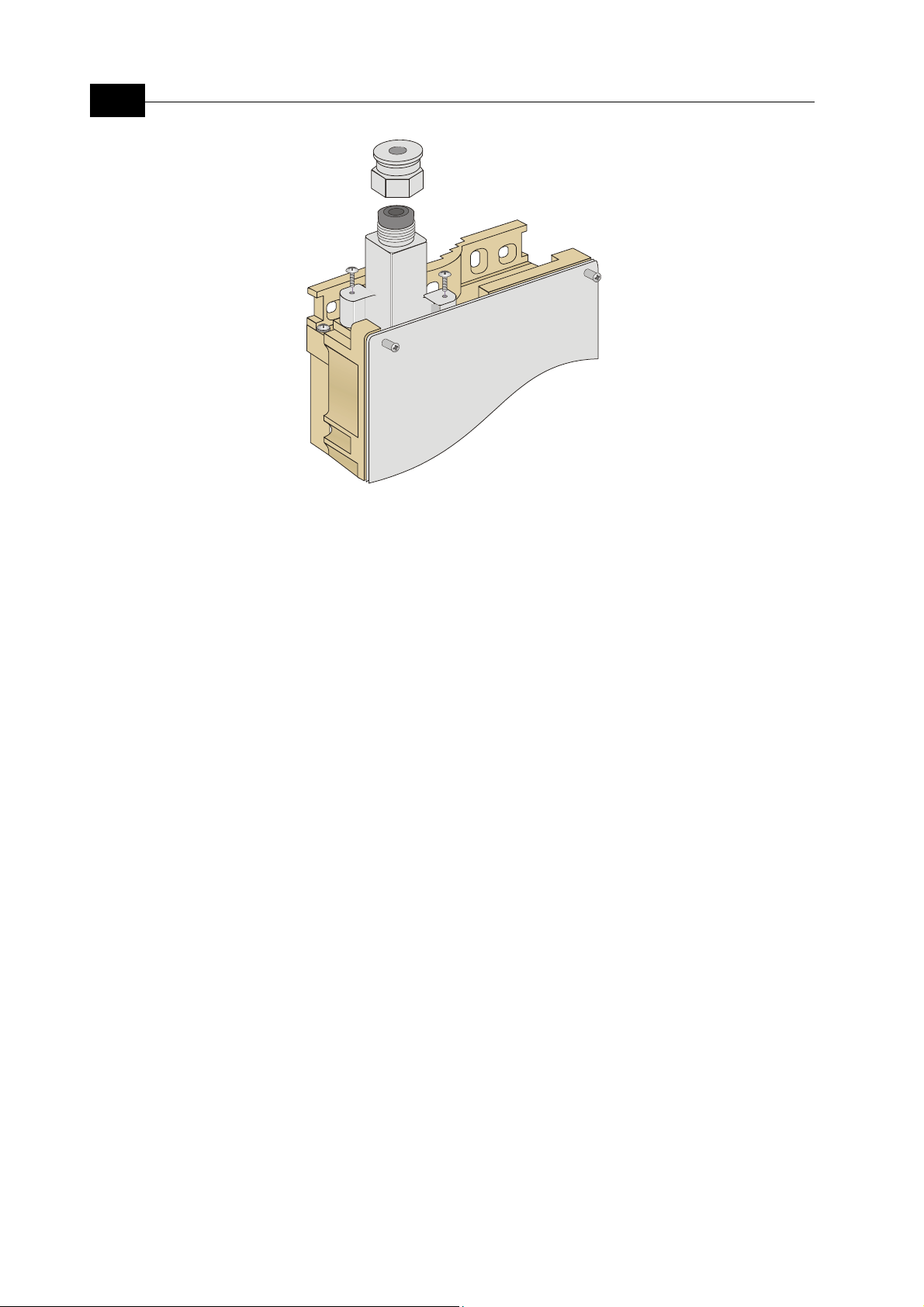
Connecting the Indoor-to-Outdoor Cable
The following steps and figure illustrate how to connect the indoor-to-outdoor
cable. The cable is supplied by Alvarion with an RJ-45 on the outdoor end, with
the other end open to facilitate easy routing through holes to the location intended
for the indoor unit. The cable is supplied together with the waterproof service box.
The kit includes also an O-ring for the service box, an RJ-45 connector and a
connector cover.
2-12
BreezeNET DS.11 Series User Manual
Figure
2-5: The Waterproof Service Box
1. Place the O-ring of the service box in its intended location.
2. Connect the Ethernet cable to the outdoor unit’s RJ-45 connector.
3. Attach the service box to the outdoor unit and then tighten the top nut. Make
sure that the O-ring is in its intended location to verify proper sealing.
4. Route the cable to the location selected for the indoor unit.
5. Insert the protective cover before connecting the indoor end to the RJ-45
connector. Prepare the indoor end of the cable according to the instructions in
Appendix B.
 Loading...