

Page 1
PDS8/PDS8CB
Dual Input Power Distribution Module
Overview:
PDS8/PDS8CB dual input power distribution module is designed to steer the power from either two (2) low voltage AC or DC power
sources. This power is distributed over a total of eight (8) fuse/PTC protected outputs.
For use with Maximal, eFlow, ULX, and Trove series of power supplies.
Specifications:
Agency Listings:
• UL 294 6th Edition: Access Control System Units.*
• ULC-S319: Electronic Access Control Systems.**
Power Inputs:
• Input 1 and Input 2 voltage range:
PDS8: 5VDC to 24VDC, up to 10A each or
16VAC to 28VAC, 60Hz, up to 10A each,
20A total input.
PDS8CB: 5VDC to 24VDC up to 10A each or
16VAC to 28VAC, 60Hz, up to 10A each,
16A total input.
Outputs:
• PDS8: Fuse protected outputs rated @ 3A per output,
non power-limited. Total output 20A max.
Do not exceed the individual power supply ratings.
PDS8CB: PTC protected outputs rated @ 2A per output,
Class 2 power-limited. Total output 16A max.
Do not exceed the individual power supply ratings.
Total output current should not exceed max. current
rating of the power supplies employed on each input.
See Maximum Output of Altronix Power Supplies below.
Outputs (cont’d):
• Any of the eight (8) fuse/PTC protected power outputs
are selectable to follow power Input 1 or Input 2.
Output voltage of each output is the same as the input voltage
of the input selected.
• Individual outputs may be set to OFF position for servicing.
• Surge suppression.
Outputs Ratings:
PDS8: 4.8 - 24 VDC or 15.8 - 28 VAC
PDS8CB: 4.8 - 24 VDC or 15.6 - 28 VAC
Fuse Ratings:
• Main input fuses rated @ 10A/32V each.
• PDS8: individual output fuses rated @ 3A/32V each.
LED Indicators:
• Eight (8) individual output LEDs.
Environmental:
• Operating temperature: 0ºC to 49ºC ambient.
• Humidity: 20 to 85%, non-condensing.
Mechanical:
• Product weight (approx.): 0.4 lbs. (0.18 kg).
• Shipping weight (approx.): 0.5 lbs. (0.23 kg).
*UL 294 Levels: Attack: I, Endurance: IV, Line security: I, Stand-by power: I.
**ULC-S319: Class 1.
Maximum Output of Altronix Power Supplies:
DC Power Supplies
UL Listed or Recognized Power Supply Output Voltage Max. Output Current
AL300ULXB2
AL400ULXB2
AL600ULXB
AL1012ULXB
AL1024ULXB2
eFlow3NB
eFlow4NB
eFlow6NB
eFlow102NB
eFlow104NB
VR6
UL Recognized Power Supply Output Voltage Max. Output Current
T2428100
T2428175
T2428300
*Total load must not exceed 10A.
12VDC or 24VDC 2.5A
12VDC or 24VDC 12VDC @ 4A or 24VDC @ 3A
12VDC or 24VDC 6A
12VDC 10A
24VDC 10A
12VDC or 24VDC 2A
12VDC or 24VDC 4A
12VDC or 24VDC 6A
12VDC 10A
24VDC 10A
5VDC or 12VDC 6A
AC Power Supplies
24VAC or 28VAC 24VAC @ 4A or 28VAC @ 3.5A
24VAC or 28VAC 24VAC @ 7.25A or 28VAC @ 6.25A
24VAC or 28VAC 24VAC @ 14A or 28VAC @ 12.5A*
Page 2
Installation Instructions:
Wiring methods shall be in accordance with the National Electrical Code/NFPA 70/NFPA 72/ANSI, with Canadian Electrical Code
CSA C22.1, and with all local codes and authorities having jurisdiction. Product is intended for indoor use only and should be installed
by qualified personnel.
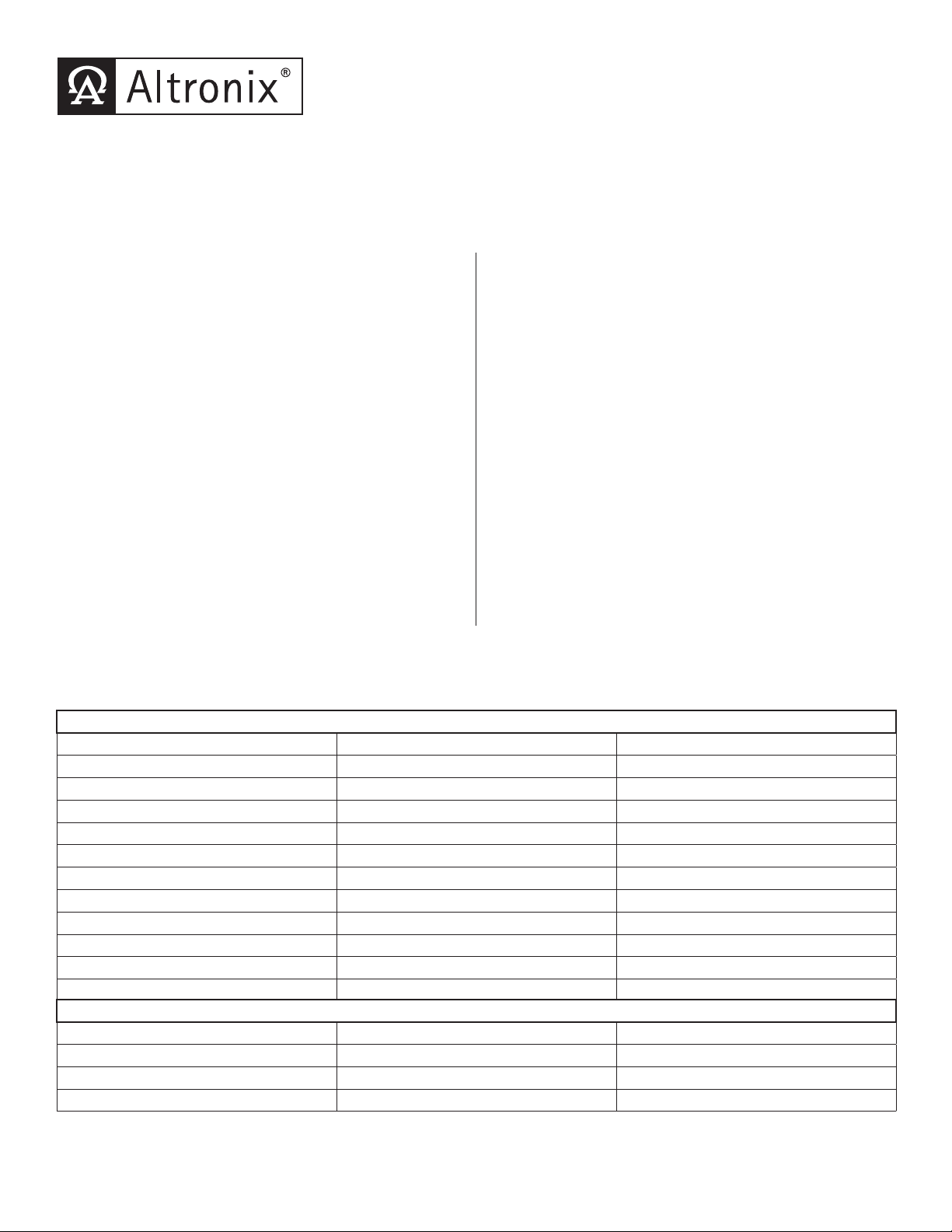
1. Mount PDS8/PDS8CB in the desired location/enclosure.
2. Ensure all output jumpers [OUT1 - OUT8] are placed in the OFF (center) position marked [•].
3. Connect low voltage AC or DC power supplies to terminals marked [+ IN1 -- ], [+ IN2 -- ] (Fig. 1, pg. 2, Fig. 2 pg. 2).
Note: You can not combine AC and DC power supplies.
4. Set each output [OUT1 - OUT8] to route power from power supply 1 or 2 (jumper position 1 or 2) (Fig. 1, pg. 2, Fig. 2 pg. 2).
Note: Measure output voltage before connecting devices. This helps avoiding potential damage.
5. Turn power off before connecting devices.
6. Connect devices to terminal pairs 1 to 8, marked [P (Positive) - OUT1-OUT8, N (Negative)] (Fig. 1, pg. 2, Fig. 2 pg. 2).
Note: For DC devices carefully observe polarity. For AC devices polarity is not observed.
7. Turn main power on after all devices have been connected.
Fig. 1 - PDS8
Fig. 1a
Power
Supply 1
Power
Supply 2
+ INP1
--
+ INP2
--
DM1 +
IN2 Fuse
10
Common (--- )
DM2 +
OFF
IN1
IN2
3
IN1 Fuse
10
<
1 off 2
>
Out1
<
1 off 2
3
>
PDS8
PDS8CB
<
1 off 2
333333
Out2
>
Out3
<
1 off 2
>
Out4
<
1 off 2
Out5
>
P
OUT1 OUT2 OUT3 OUT4 OUT5 OUT6 OUT7 OUT8
N
1 2 3 4 5 6 7 8
Common Power Outputs (NEG)
Dual Voltage
Power Distribution
Module
<
1 off 2
Out6
>
DM1 +
<
1 off 2
Out7
>
Common (--- )
DM2 +
<
1 off 2
Out8
>
(P) Positive
DC outputs
(N) Negative
DC outputs
Fig. 1a - Connector plug facilitates quick installation with optional VR6 voltage regulator module (see pg. 2).
CAUTION: To avoid risk of electric shock or fire hazard, replace fuses with the same type and rating:
Input fuses: 10A/32V, Output fuses: 3A/32V.
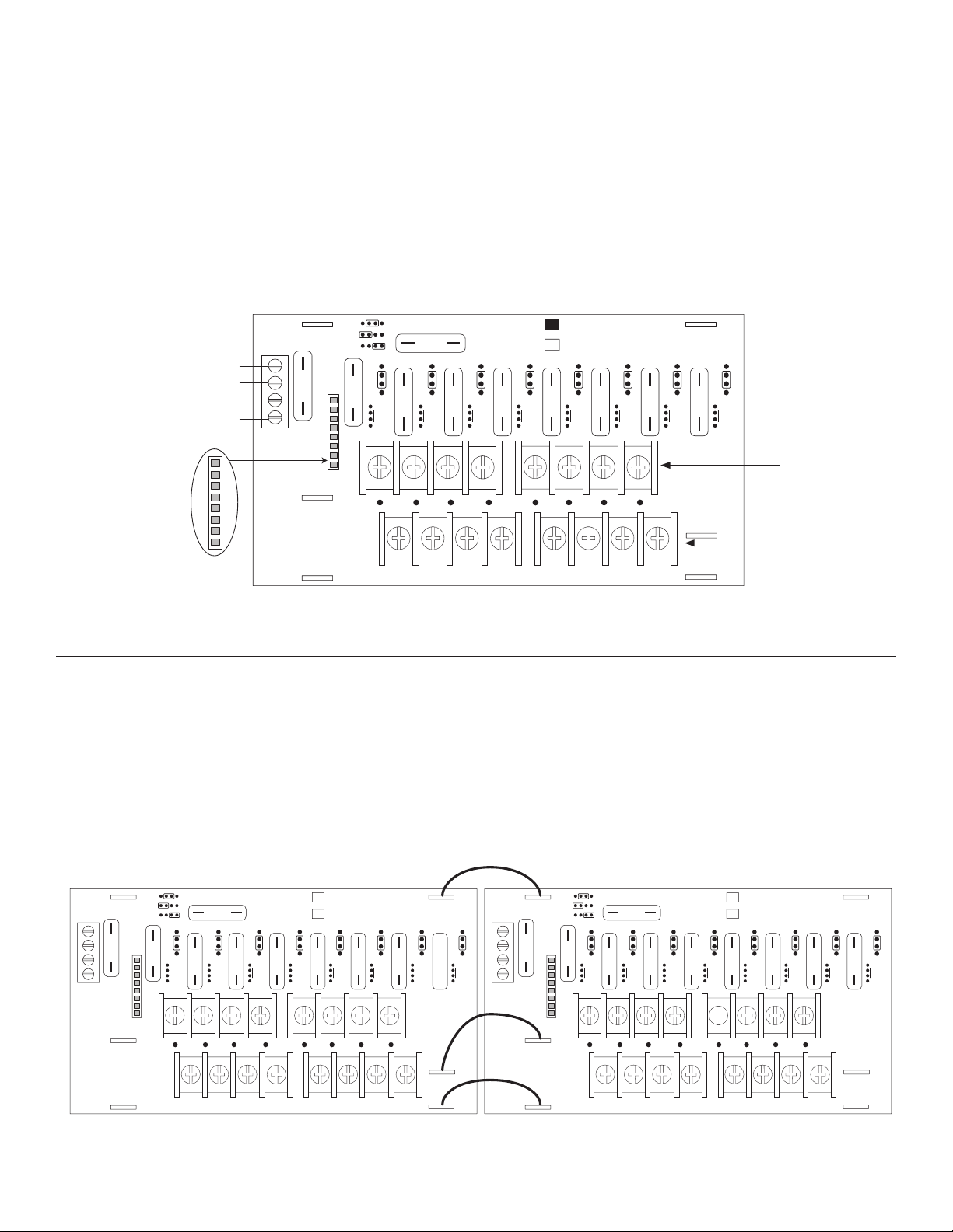
Daisy Chaining Two (2) PDS8/PDS8CB Dual Output Power Distribution Modules:
Use 18 AWG or larger UL Listed wire equipped with 1/4” UL Recognized quick connect terminals rated for proper voltage/
current for all jumper connections.
1. Connect first PDS8/PDS8CB board’s spade lug marked [DM1+] to the second PDS8/PDS8CB board’s spade lug marked
[DM1+] (Fig. 2, pg. 2).
2. Connect first PDS8/PDS8CB board’s spade lug marked [Common (-- )] to the second PDS8/PDS8CB board’s spade lug marked
[Common (-- )] (Fig. 2, pg. 2).
3. Connect first PDS8/PDS8CB board’s spade lug marked [DM2+] to the second PDS8/PDS8CB board’s spade lug marked
[DM2+] (Fig. 2, pg. 2).
4. Complete steps 4-8 from page 1.
Jumper Wires
with Spade Lugs
Fig. 2
+ INP1
--
+ INP2
--
DM1 +
IN2 Fuse
10
Common (--- )
DM2 +
OFF
IN1
IN2
3
IN1 Fuse
<
1 off 2
3
Out1
>
PDS8
10
PDS8CB
<
<
<
1 off 2
1 off 2
3333 33
Out2
Out3
>
>
<
1 off 2
1 off 2
Out4
>
>
P
OUT1 OUT2 OUT3 OUT4 OUT5 OUT6 OUT7 OUT8
N
1 2 3 4 5 6 7 8
Common Power Outputs (NEG)
Dual Voltage
Power Distribution
Module
<
1 off 2
Out5
Out6
>
DM1 +
<
1 off 2
Out7
>
Common (--- )
DM2 +
DM1 +
+ INP1
--
+ INP2
<
1 off 2
Out8
--
>
OFF
IN1
IN2
IN2 Fuse
10
3
IN1 Fuse
<
1 off 2
3
Out1
>
PDS8
10
PDS8CB
<
<
1 off 2
3333 33
Out2
>
<
1 off 2
1 off 2
Out3
Out4
>
>
Dual Voltage
Power Distribution
Module
<
<
1 off 2
1 off 2
Out5
Out6
>
>
P
Common (--- )
OUT1 OUT2 OUT3 OUT4 OUT5 OUT6 OUT7 OUT8
N
DM2 +
1 2 3 4 5 6 7 8
Common Power Outputs (NEG)
- 2 - PDS8 / PDS8CB
DM1 +
<
1 off 2
Out7
>
Common (--- )
DM2 +
<
1 off 2
Out8
>
Page 3

VR6 - Voltage Regulator
C20
Overview:
VR6 voltage regulator is designed to convert a 24VDC input into a regulated 5VDC or 12VDC output.
Refer to VR6 Installation Intructions Rev. 050517.
Specifications:
Power Input / Output:
• Input: 24VDC @ 1.75A – Output: 5VDC @ 6A.
Input: 24VDC @ 3.5A – Output: 12VDC @ 6A.
Output:
• 5VDC or 12VDC regulated output.
• Output rating 6A max.
• Surge suppression.
Connecting PDS8/PDS8CB to VR6:
1. Mount VR6 in the desired location/enclosure.
2. Plug-in male 8-pin connector to female 8-pin receptacle on VR6 board (Fig. 4, pg. 3).
3. Fasten standoffs (Fig. 4, pg. 2). Use metal standoff over mounting hole with star pattern (Fig. 3, pg. 3).
4. Align 8-pin male connector with female receptacle of PDS8/PDS8CB, then mount (Fig. 4, pg. 3, Fig 1a, pg. 2).
5. Connect 24VDC power supply to terminal marked [+IN1 --- ] of PDS8/PDS8CB (Fig. 4, pg. 3).
6. Select output voltage 5VDC or 12VDC using switch [S1] on VR6.
7. Complete steps 4-8 from page 2.
Fig. 3
LED Indicators:
• Input and output LEDs.
Electrical:
• Operating temperature: 0ºC to 49ºC ambient.
• Humidity: 20 to 85%, non-condensing.
Mechanical:
• Product weight (approx.): 0.4 lbs. (0.18 kg).
• Shipping weight (approx.): 0.5 lbs. (0.23 kg).
Fig. 4
--
+ IN
+ OUT
PDS8/PDS8CB
DM1+
VR6VR6
--
--
+ IN1
+ IN
Common(-)
+ IN2
--
--
+ OUT
--
PDS8 / PDS8CB - 3 -
Page 4

Notes:
Altronix is not responsible for any typographical errors.
140 58th Street, Brooklyn, New York 11220 USA | phone: 718-567-8181 | fax: 718-567-9056
website: www.altronix.com | e-mail: info@altronix.com | Lifetime Warranty | Made in U.S.A.
IIPDS8 - Rev. 070116 G28Q
- 4 - PDS8 / PDS8CB
MEMBER
 Loading...