

Page 1
PD4CB - Power Distribution Module
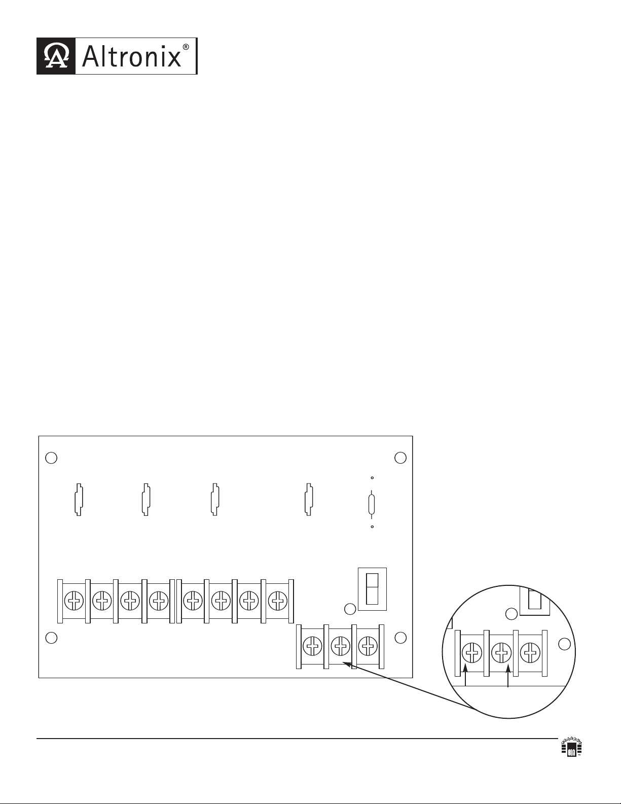
INPUT
1P 1N 2P 2N
LED
1P, 2P, 3P, 4P = FUSED OUTPUTS
1N, 2N, 3N, 4N = COMMON OUTPUTS
ON OFF
SW1
F1
3P 3N 4P 4N
F2 F3 F4
NPS
INPUT
LED
ON OFF
SW1
NPS
Overview:
The PD4CB power distribution module converts a single AC or DC input into four (4) PTC protected outputs.
Specifications:
Input:
• Handles up to 28VAC/VDC.
Outputs:
• Four (4) PTC protected outputs (PTC’s are rated @ 2.5 amp).
• Surge suppression.
Visual Indicators:
• Power output LED indicator.
Additional Features:
• Power ON / OFF switch.
Board Dimensions (approximate):
5.25"L x 3.25"W x 1"H
Installation Instructions:
1. Mount PD4CB in desired location/enclosure.
2. Connect the desired power supply output to terminals marked [INPUT] (
Note: If using DC voltage, left terminal is NEG. (-) and right terminal is POS. (+) (Fig. 1A).
3. Measure output voltage before connecting devices. This helps avoid potential damage.
4. Set power switch [SW1] to the OFF position.
5. Connect each device to terminal pairs 1 to 4, marked [1P-1N thru 4P - 4N].
6. Set power switch [SW1] to the ON position.
Fig. 1A).
Fig. 1
Altronix is not responsible for any typographical errors. Product specifications are subject to change without notice.
140 58th Street, Brooklyn, New
website: www.altronix.com, e-mail: info@altronix.com, Lifetime
IIPD4CB - Rev. 112204
York 11220 USA, 718-567-8181, fax: 718-567-9056
Warranty, Made in U.S.A.
K22D
Fig. 1A
Neg. (--- )
Pos. (+ )
MEMBER
 Loading...