

Page 1
OLS20 - Offline Power Supply/Charger
MADE IN USA
LGN
--- BAT +
O
pen - 24V
Closed - 12V
S
W1
CONNECTOR #1
Gr WhBk
DC
PTC2
V
R1
A
C
--- DC +
2A
250V
Overview:
OLS20 power supply/charger converts 115VAC / 60Hz input, into a 12VDC @ 1 amp or 24VDC @ .5 amp of
continuous supply current (refer to specifications). This general purpose power supply has a wide range of application
for access control and security system accessories that require additional power.
Specifications:
Input:
• 115VAC / 60Hz, .5 amp.
Output:
• 12VDC or 24VDC selectable operation.
• .5 amp continuous supply current @ 24VDC
1 amp continuous supply current @ 12VDC.
• Filtered and electronically regulated outputs.
• Short circuit and thermal overload protection.
Battery Backup:
• Built-in charger for sealed lead acid or gel type batteries.
Maximum charge current .5 amp.
•
• Automatic switch over to stand-by battery when AC fails.
Additional Features:
• AC input and DC output LED indicators.
• Includes battery leads.
Board Dimensions (approximate): 2.6”W x 3.1”L x 1.3”H
Specified at 25˚ C ambient.
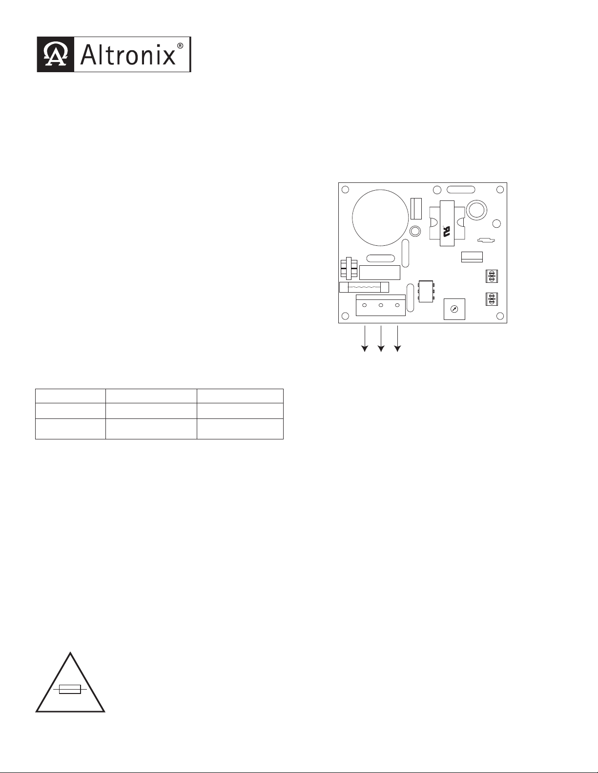
Fig. 1
Voltage Output Selection Table:
Output VDC Switch Position Max. Load DC
12VDC SW 1 - Closed 1.2 amp
24VDC
SW1 - Open .5 amp
Installation Instructions:
The OLS20 should be installed in accordance with The
National Electrical Code and all applicab
le Local Re
1. Mount the OLS20 in desired location/enclosure.
2. Set the OLS20 to desired DC output voltage via SW1
(refer to Voltage Output Selection Table).
3. Connect AC power to connector #1
(Fig. 1) (black & white flying leads) and ground (green flying lead)
Use 18 AWG or larger for all power connections(Battery, AC input).
Keep power limited wiring separate from non-power limited wiring (115VAC / 60Hz Input, Battery Wires).
vided.
Minim
4. Measure output voltage before connecting devices. This helps avoid potential damage.
um .25” spacing m
ust be pr
o
5. Connect devices to be powered to terminals marked [--DC +]
When the use of stand-by batteries are desired, they must be lead acid or gel type.
6.
Connect battery to terminals marked [-- BAT +]
Use two (2) 12VDC batteries connected in series for 24VDC operation.
Note: When batteries are not used a loss of AC will result in the loss of output voltage.
gulations.
(Fig. 1).
(Fig. 1).
For continuous protection against fire replace fuse with the
same type and rating 5mm - 20mm, 250V, 2A
Page 2
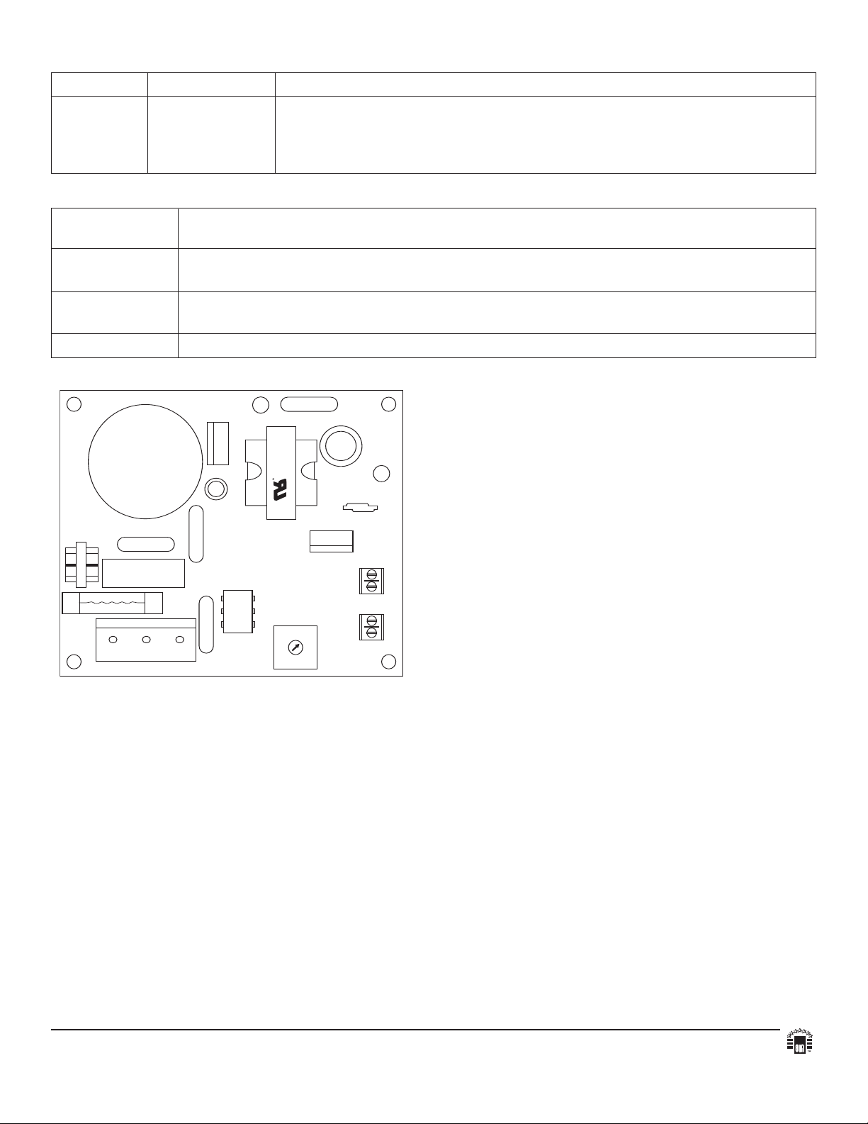
MADE IN USA
LGN
--- BAT +
Open - 24V
Closed - 12V
SW1
DC
PTC2
VR1
AC
--- DC +
LED Diagnostics:
Red (DC) Green (AC) Power Supply Status
O
N ON Normal operating condition.
ON OFF Loss of AC, Stand-by battery supplying power.
OFF ON No DC output. Short circuit or thermal overload condition.
OFF OFF Loss of AC. Discharged or no stand-by battery. No DC output.
Terminal Identification:
Terminal Function/Description
Legend
L, G, N Connect 115 VAC to these terminals:
Black to Hot, White to Neutral, Green to ground.
+ DC - 12VDC @ 1.2 amp continuous supply current.
24VDC @ .5 amp continuous supply current.
- BAT + Stand-by battery connections. Maximum charge rate .3 amp.
Altronix is not responsible for any typographical errors. Product specifications are subject to change without notice.
140 58th Street, Brooklyn, New York 11220 USA, 718-567-8181, fax: 718-567-9056
website: www.altronix.com, e-mail: info@altronix.com, Lifetime
IIOLS20 - Rev. 080905 H09E
Warranty, Made in U.S.A.
MEMBER
 Loading...