

Altronix NETWAYSP8B, NETWAYSP8PL, NETWAYSP8WP, NETWAYSP8WPN, NETWAYSP8WPX Installation Guide
...Page 1

8-Port Ethernet over Fiber
PoE+ Hardened Switches
Installation Guide
Models include:
Embedded
™
NetWaySP8WP
- Includes Fiber Optic SFP 1G Link,
8-port PoE+ switch and power supply.
- NEMA4/4X, IP66 rated Outdoor enclosure.
NetWaySP8WPX
- Includes Fiber Optic SFP 1G Link,
8-port PoE+ switch and power supply.
- NEMA4/4X, IP66 rated Outdoor enclosure.
- Accommodates up to four (4)
12VDC/4AH batteries.
NetWaySP8X
- Includes Fiber Optic SFP 1G Link,
8-port PoE+ switch and power supply.
- NEMA1 rated Indoor enclosure.
NetWaySP8WPN
- Includes Fiber Optic SFP 1G Link and
8-port PoE+ switch
(uses external power supply).
- NEMA4/4X, IP66 rated Outdoor enclosure.
NetWaySP8PL
- Includes Fiber Optic SFP 1G Link,
8-port PoE+ switch and power supply.
- Backplane version.
NetWaySP8B
- Fiber Optic SFP 1G Link and
8-port PoE+ switch
- Board only.
I.T.E. 43KC
DOC#: NetWaySP8 Rev. 032117
More than just power.
TM
Page 2

Altronix NetWay Indoor/Outdoor Ethernet over Fiber PoE Hardened Switches provide two (2) 1Gb SFP ports and
eight (8) PoE+ (30W) ports or up to two (2) Hi-PoE (60W) ports, passing data and power to PoE/PoE+ compliant
devices. Cameras/edge devices may be located up to 100m from the unit. Features also include an integral battery
charger for applications requiring backup and embedded LINQ Technology to monitor, control, and report power
and diagnostics from anywhere.
Features:
Overview:
Input:
• 115VAC, 60 Hz, 2.5A or 230VAC, 50/60 Hz, 1.3A.
NetWaySP8B/NetWaySP8WPN:
48-55V UL Listed ITE power supply (up to 120W)
Power Output:
• Eight (8) ports PoE+ (30W) or up to
two (2) Hi-PoE (60W) ports.
• IEEE 802.3at (30W) and IEEE 802.3af (15W)
compliant.
• 115W total power.
• Integral surge protection.
Fiber Port:
• Two (2) Gigabit SFP ports.
• Use with SFP module 1000Base-X (1Gb),
compliant to Class 1 laser product (not included).
Ethernet Ports:
• Six (6) 10/100 Mbps and
two (2) 10/100/1000 Mbps ports.
• Connectivity: RJ45, auto-crossover.
• Wire type: 4-pair CAT5 or better structured cable.
• Distance: up to 100m.
• Speed: 10/100/1000 Mbps, half/full duplex,
auto negotiation.
Battery Backup:
• Built-in charger for sealed lead acid or
gel type batteries.
• Automatic switch over to stand-by battery
when AC fails.
LEDs:
• Individual PoE On LEDs for each port.
• Individual IP Link status, 10/100Base-T/active
LEDs for each port.
• ALOS LED indicates fiber connection for SFP port.
• Heartbeat LED indicates proper operation of the unit.
Environmental:
• Refer to Technical Specifications Chart on page 4
for Environmental Conditions.
Applications:
• Provides PoE / PoE+ / Hi-PoE for cameras/devices.
LINQ Technology:
• Remote network management allows for camera/
device reset and monitoring.
• Provides local and/or remote access to critical
information via LAN/WAN.
• Email and Windows Dashboard Alert notifications
report real-time diagnostics.
• Event log tracks history.
Accessories:
NetWaySP1A
• Ethernet over Fiber Media Converter/Repeater for applications requiring an additional SFP (Fiber)
port (Fig. 3, pg. 6).
Mechanical:
NetWaySP8WP
• NEMA4/4X, IP66 Rated enclosure for outdoor use.
• Dimensions (H x W x D approx.):
13.31” x 11.31” x 5.59”
(338.1mm x 287.3mm x 142mm).
NetWaySP8WPN
• NEMA4/4X, IP66 Rated enclosure for outdoor use.
• Dimensions (H x W x D approx.):
13.31” x 11.31” x 5.59”
(338.1mm x 287.3mm x 142mm).
NetWaySP8WPX
• NEMA4/4X, IP66 Rated enclosure for outdoor use.
• Accommodates four (4) 12VDC/4AH batteries
(48V of backup).
• Dimensions (H x W x D approx.):
17.375” x 12” x 6.5”
(441.3mm x 304.8mm x 165.1mm).
NetWaySP8X
• Dimensions (H x W x D approx.):
13.5” x 13” x 3.25” (342.9mm x 330.2mm x 83mm).
NetWaySP8PL
• Dimensions (H x W x D approx.):
10.75” x 8.875” x 2.375”
(273.1mm x 225.4mm x 60.3mm).
NetWaySP8B
• Dimensions (L x W x D approx.):
5.625” x 4.5” x 0.625”
(158.8mm x 142.9mm x 15.9mm).
• UL/cUL Listed for Information Technology Equipment (UL 60950-1),
Agency Listings:
Information Technology Equipment to Be Installed Outdoors (UL 60950-22).
• CE approved.
- 2 - NetWaySP4 Series
Page 3
Wiring methods shall be in accordance with the National Electrical Code/NFPA 70/ANSI, and with all local
30W 60W
PORT 2
NetWaySP8B
Factory Reset
PoE5
PoE7
PoE6
PoE8
Input:
48V-56VDC
+
--
PORT 7
PORT 8
Metal Standoffs
codes and authorities having jurisdiction. All units should be installed by a trained service personnel.
NetWaySP8WP/SP8WPN/SP8WPX Enclosure Mounting and Installation:
1. Remove backplane from enclosure prior to drilling. Do not discard hardware.
Note: Make sure that hardware will not interfere with components of the circuit board.
2. Mark and drill desired inlets on the enclosure to facilitate wiring. Maximum NEMA type 4X rated fittings to
be used are 0.5”. Follow manufacturer’s specifications for the appropriate size opening.
Note: Inlets for conduit fittings should only be made on the bottom of the enclosure.
UL Listed NEMA type 4X rated conduit connector/hubs shall be used for the appropriate size inlets.
3. Clean out the inside of enclosure before remounting circuit board.
4. Mounting NEMA4/4X rated enclosure (Enclosure Dimensions, pgs. 11-12):
Wall mount: Mount unit in desired location. Mark and drill holes to line up with the top and bottom holes of
the enclosure flange. Secure enclosure with appropriate fasteners (e. g. screws and anchors;
bolts and locking nuts, etc.) that are compatible with mounting surface and are of sufficient
length/construction to ensure a secure mount (Fig. 5, pg. 8).
Pole Mount: Refer to Figs. 6 - 10, pg. 8.
NetWaySP8WPX only: In order to properly mount NetWaySP8WPX on a pole using Altronix PMK1,
additional holes need to be drilled in the enclosure’s flanges, so the distance between those holes is 10”.
5. Mount backplane in enclosure with hardware.
6. To facilitate wire entry utilize weather-tight NEMA rated connectors (supplied), bushings, and cable.
NetWaySP8X Enclosure Mounting and Installation:
1. Mount unit in the desired location. Mark and predrill holes in the wall to line up with the top two keyholes
in the enclosure. Install two (2) upper fasteners and screws in the wall with the screw heads protruding.
Place the enclosure’s upper keyholes over the two (2) upper screws; level and secure. Mark the position of
the lower two (2) holes. Remove the enclosure. Drill the lower holes and install two fasteners. Place the
enclosure’s upper keyholes over the two (2) upper screws. Install the two (2) lower screws and make sure to
tighten all screws (Enclosure Dimensions, pg. 9). Secure enclosure to earth ground.
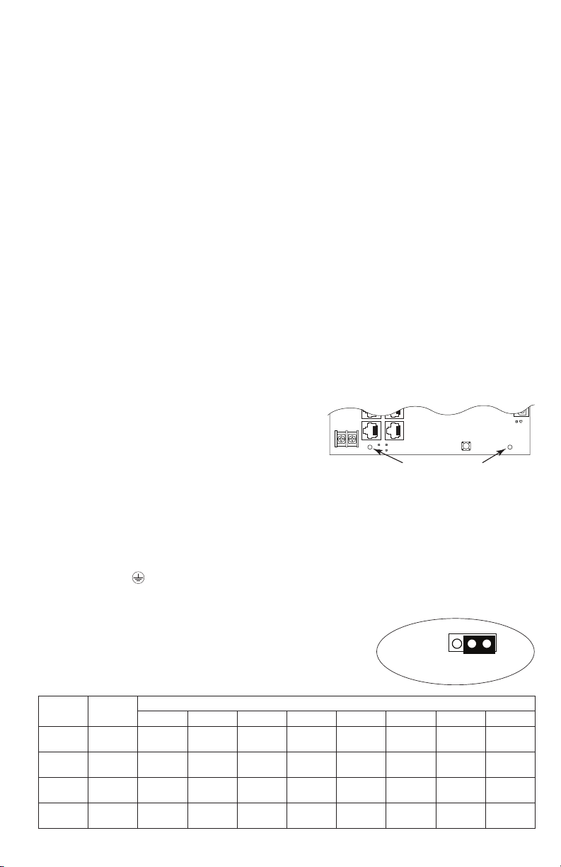
NetWaySP8B/SP8PL Mounting and Installation:
1. Mount board/backplane in the desired location/enclosure
with hardware supplied.
2. NetWaySP8B: Connect 56VDC/120W max power source
to terminal marked [+] and [–].
Note: For proper earth ground connections on NetWaySP8B
fasten metal standoffs (provided) to threaded studs at indicated
board mounting holes (shown on the right).
This is recommended for better environmental immunity.
Installation:
1. For NetWaySP8WP, NetWaySP8WPX, NetWaySP8X, and NetWaySP8PL:
Before powering unit, set input voltage selection switch to proper Input Voltage position (Fig. 3a, pg. 6).
Units are factory set for 115VAC.
2. Secure cabinet to earth ground. Connect AC power from overcurrent protective device circuit breaker
(20A @ 115VAC, 60Hz, 16A @ 230VAC, 50/60Hz) to the terminals marked [L, N] on power supply board
(Fig. 3, pg. 6). Use 14AWG or larger for all power connections (Battery, DC output, AC input).
Connect ground lug to earth or green branch wire (12AWG min.).
Note: For NetWaySP8WPN use external 48-55V UL Listed ITE power supply, carefully observing
correct polarity (Fig. 4, pg. 7). Keep power-limited wiring separate from non power-limited
wiring by utilizing separate knockouts/inlets.
Minimum 0.25” spacing must be provided.
CAUTION: Do not touch exposed metal parts.
Shut branch circuit power before installing or servicing
equipment. There are no user serviceable parts inside.
Refer installation and servicing to qualified service personnel.
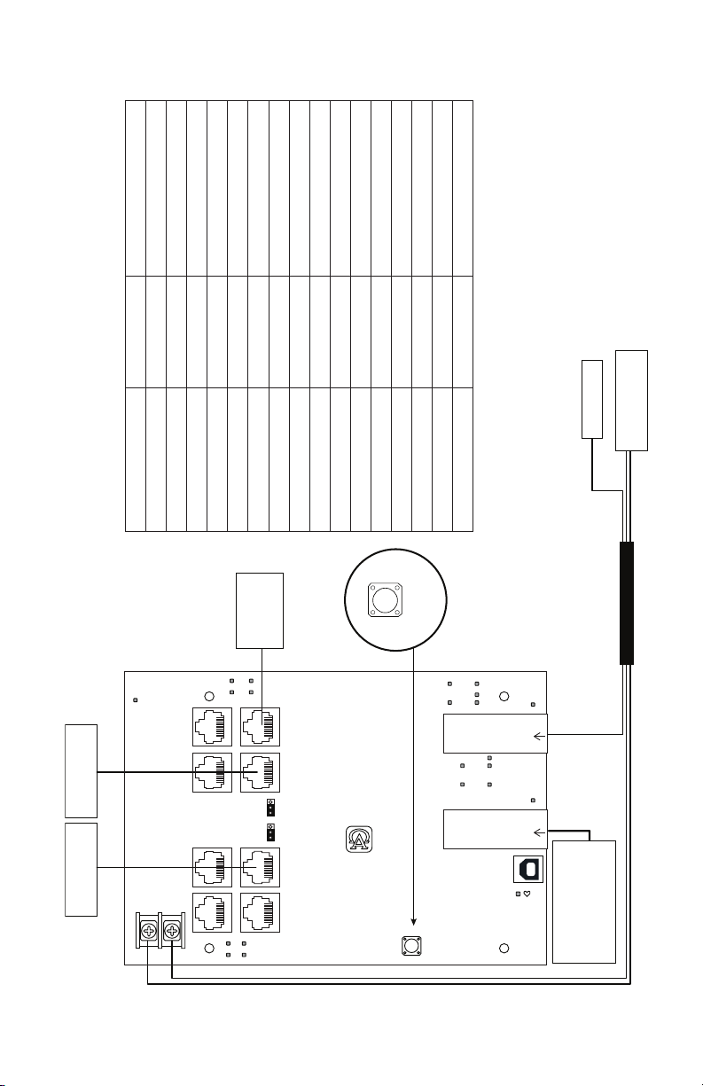
3. Port Configurations (Fig. 1, pg. 3; Fig. 3b, pg. 6):
Installation Instructions:
Jumper
Jumper
PORT 4 30W
PORT 6 30W ----- ----- ----- -----
PORT 4 60W
PORT 6 60W ----- ----- ----- -----
NetWaySP4 Series - 3 -
Position
1 2 3 4 5 6 7 8
30W and
Data
Data
Only
30W and
Data
Data
Only
Structured Cable Ports
30W and
Data
Data
Only
30W and
Data
60W and
Data
----- ----- ----- -----
30W and
30W and
Data
----- ----- ----- -----
Data
60W and
Only
Data
Data
30W and
Data
Data
Only
30W and
Fig. 1
Data
Data
Only
Page 4

4. Connect structured cables from port marked [Port 1] to [Port 8] on NetWay unit to PoE-compliant cameras/
edge devices (Fig. 3, pg. 6). Note: All interconnected devices must be UL Listed.
5. Insert SFP module into port(s) marked [SFP], then connect cable to the SFP module on NetWaySP8B to the
corresponding input of an SFP switch (Fig. 3, pg. 6).
6. Battery Backup (if desired): Connect four (4) 12VDC batteries wired in series to terminals marked
[+ BAT –] (Fig. 3, pg. 6), carefully observing polarity.
When use of stand-by batteries is desired, they must be lead acid or gel type.
Note: When batteries are not used, a loss of AC will result in the loss of output voltage.
7. Please ensure that the cover is secured with:
Key lock and screws for NetWaySP8X, security bolt for NetWaySP8WP, NetWaySP8WPN and
NetWaySP8WPX.
Altronix P1MM and P1SM10 are hot-pluggable SFP fiber transceiver modules and are readily usable with all
Altronix Spectrum fiber optic equipment for 1Gb transmission rates.
P1MM - For use with Multi-Mode Fiber for distances up to 550m.
P1SM10 - For use with Single-Mode Fiber for distances up to 10km.
Technical Specifications:
Parameter Description
Recommended Altronix SFP Modules:
Number of Ports
Input Power
Requirements
Environmental
Conditions
Weights (approx.)
Eight (8) ports PoE+ (30W) or up to two (2) Hi-PoE (60W) ports.
Two (2) Gigabit SFP Ports.
115VAC, 60Hz, 2.5A or 230VAC, 50/60Hz, 1.3A.
NetWaySP8B/NetWaySP8WPN: 48-55V UL Listed ITE power supply
Operating Ambient Temperature:
NetWaySP8WP/NetWaySP8WPX: 60W: -40ºC to 75ºC (-40ºF to 167ºF);
75W: -40ºC to 70ºC (-40ºF to 158ºF);
100W: -40ºC to 55ºC (-40ºF to 131ºF);
115W: -40ºC to 45ºC (-40ºF to 113ºF).
NetWaySP8X: 115W: -40ºC to 50ºC (-40ºF to 122ºF).
NetWaySP8B/NetWaySP8WPN: 115W: -40ºC to 75ºC (-40ºF to 167ºF).
Relative Humidity: 85%, +/- 5%
Storage Temperature: -40ºC to 85ºC (-40ºF to 185ºF).
Operating Altitude: -304.8 to 2,000m.
Model Product Weight Shipping Weight
NetWaySP8WP
NetWaySP8WPN
NetWaySP8WPX
NetWaySP8X
NetWaySP8PL
NetWaySP8B
10.72 lbs. (4.86 kg)
7.9 lbs. (3.58 kg)
15 lbs. (6.8 kg)
6.85 lbs. (3.11 kg)
2.8 lbs. (1.27 kg)
0.45 lbs. (0.2 kg)
12.1 lbs. (5.49 kg)
10.2 lbs. (4.63 kg)
17.5 lbs. (7.9kg)
7.75 lbs. (3.51 kg)
4.2 lbs. (1.9 kg)
1 lbs. (0.45 kg)
Configuring Units for Network Connection
Please be sure to visit altronix.com for latest firmware and
installation instructions
Factory Default Settings
• IP Address: 192.168.168.168
• User Name: admin
• Password: admin
1. Set the static IP address for the laptop to be used for programming to the same network IP address as the
NetwaySP8. The default address of the NetwaySP8 is 192.168.168.168, E.I. 192.168.168.200.
2. Connect one end of the network cable to the network jack on the NetwaySP8 and the other to the network
connection of the laptop.
- 4 - NetWaySP4 Series
Page 5

3. Open a browser on the computer and enter “192.168.168.168” into the address bar.
A dialog box Authentication Required will appear requesting both user name and password.
Enter the default values here. Click on the button labeled Log In.
4. The status page of the NetWaySP8 will appear. Click on the tab labeled Network Settings.
This will open the Network Setting screen. In this screen the MAC Address of the NetWaySP8 module will
be found along with the Network Settings and Email Settings.
Network Settings:
In the IP Address Method field select the method that the IP Address for the NetWaySP8 will be obtained
(STATIC or DHCP), then follow the appropriate steps.
Static:
A. IP Address: Enter the IP address assigned to the NetWaySP8 by the network administrator.
B. Subnet Mask: Enter the Subnet of the network.
C. Gateway: Enter the TCP/IP gateway of the network access point (router) being used.
Gateway configuration is required to properly receive emails from the device.
D. HTTP Port: Enter the HTTP port number assigned to the NetWaySP8 module by the network
administrator to allow remote access and monitoring. The default inbound port setting is 80. HTTP is not
encrypted and unsecure. Even though HTTP can be used for remote access, it is recommended primarily
for use with LAN connections.
E. HTTPS Port: Enter the HTTPS port number assigned to the NetWaySP8 module by the network
administrator to allow remote access and monitoring. The default inbound port setting is 443.
Being encrypted and more secure, HTTPS is highly recommended for remote access.
F. Click the button labeled Submit Network Settings.
A dialog box will display “New network settings will take effect after the server is rebooted”. Click OK.
DHCP:
A. After selecting DHCP in the IP Address Method field click the button labeled Submit Network Settings.
A dialog box will display “New network settings will take effect after the server is rebooted”. Click OK.
Next, click on the button labeled Reboot Server. After rebooting the NetWaySP8 will be set in the DHCP
mode. The IP address will be assigned by the router when the NetWaySP8 is connected to the network.
It is recommended to have the assigned IP Address reserved to ensure continued access
(see the network administrator).
B. Subnet Mask: When operating in DHCP, the router will assign the subnet mask values.
C. Gateway: Enter the TCP/IP gateway of the network access point (router) being used.
D. HTTP Port: Enter the HTTP port number assigned to the NetWaySP8 module by the network administrator
to allow remote access and monitoring. The default inbound port setting is 80. HTTP is not encrypted and
unsecure. Even though HTTP can be used for remote access, it is recommended primarily for use with
LAN connections.
E. HTTPS Port: Enter the HTTPS port number assigned to the NetWaySP8 module by the network
administrator to allow remote access and monitoring. The default inbound port setting is 443.
Being encrypted and more secure, HTTPS is highly recommended for remote access.
F. Click the button labeled Submit Network Settings.
A dialog box will display “New network settings will take effect after the server is rebooted”. Click OK.
Heartbeat Timer:
The heartbeat timer will send a trap message indicating that the NetWaySP8 is still connected and communicating.
Setting the Heartbeat Timer:
1. Click the button labeled Heartbeat Timer Setting.
2. Select the desired time between heartbeat messaging in the Days, Hours, Minutes and Seconds in
corresponding fields.
3. Click the button labeled Submit to save setting.
Factory Reset Option:
1. Power the unit down. Allow approximately 30 seconds
for the unit to power down completely.
2. Depress Factory Reset button on NetWaySP8B while
reapplying power to the unit (Fig. 2, pg. 5; Fig. 3c, pg. 6).
Continue holding the button until the LEDs on board go
through the start up cycle, then release the button.
3. The unit returns to the original factory settings.
Factory Reset
Brooklyn, NY US
www.altronix.com
Altronix Cor
NetwaySP8B
Fig. 2
Factory Reset
NetWaySP4 Series - 5 -
Page 6

PWR
PoE/PoE+
or Hi-PoE Device
PoE/PoE+
or Hi-PoE Device
+
Batteries
To Stand-by
NetwaySP8B
Input:
--
48V-56VDC
--- DC ++ BAT –
60W
Device
IP PoE/PoE+
PoE1
PoE2
PoE3
PoE4
PORT 1
PORT 2
PORT 4 (1G)
PORT 3
PORT 4PORT 6
PORT 5
PORT 6 (1G)
PORT 8
PORT 7
PoE5
PoE6
PoE7
PoE8
60W
30W
60W
30W
PORTS 4, 6 = 10/100/1000
PORTS 1, 2, 3, 5, 7, 8 = 10/100
Altronix Corp.
Brooklyn, NY US
www.altronix.com
30W
Operation
Factory Reset
Fig. 3b
1000
100
PORT1
1000
100
PORT3
1000
100
PORT5
1000
100
PORT7
PORT2
SFP1
ALOS
PORT4
SFP Port
PORT6
SFP2
PORT8
ALOS
SFP Port
*
Fiber to the
Hardened PoE Switch
next Netway Spectrum
*Note: No limit to quantity
Switch
Fiber to
of daisy-chained units.
Daisy chaining only limited
to total bandwidth of 1Gbps.
Fig. 3c
Factory Reset
5A 250VA
230VAC 115VAC
LGN
230VAC 115VAC
Fig. 3a
Typical Applications:
Input Voltage
Selection Switch
Power Supply Board Orientation
230VAC 115VAC
Fig. 3a
Input Voltage
LGN
230VAC 115VAC
5A 250VA
Input
115/230VAC
Fig.3
- 6 - NetWaySP4 Series
NetWaySP8X - Power Supply Board Orientation NetWaySP8WP and NetWaySP8WPX
Selection Switch
--- DC ++ BAT –
board
To Input of
NetWaySP3B
Batteries
To Stand-by
Page 7
Power Requirements Power Cabling Maximum Distance (ft./m)
y
15W 12/2 11,162’ / 3403m
30W 12/2 5,581’ / 1702m
45W 12/2 3,767 / 1,148m
60W 12/2 2,739’ / 835m
75W 12/2 2,249’ / 686m
90W 12/2 1,872’ / 571m
105W 12/2 1,607’ / 490m
120W 12/2 1,408’ / 429m
15W 16/2 4,415’ / 1,346m
30W 16/2 2,207’ / 673m
45W 16/2 1,490’ / 454m
60W 16/2 1,083’ / 330m
75W 16/2 889’ / 271m
NetWaySP8WPN – Typical Application with Composite Cable
Power Distance Chart
90W 16/2 740’ / 226m
Fiber Switch
48-55V UL Listed
ITE Power Supply
Carefully observe polarit
105W 16/2 635’ / 194m
120W 16/2 557’ / 170m
Estimated distances based on starting voltage of 56VDC and accounts for a 10 volt drop.
All distances are per IEEE 802.3at standard for device power requirements of minimum
44VDC and leave an approximate 2 volts for safety and flexibility.
Typical Applications:
NetwaySP8B
PWR
PoE/PoE+
or Hi-PoE Device
PORT 1
PORT 3
PORT 5
PoE1
PoE3
Device
IP PoE/PoE+
PoE2
PoE4
PORT 2
PORT 4 (1G)
60W
PORT 4PORT 6
30W
60W
30W
PORT 6 (1G)
PORTS 4, 6 = 10/100/1000
PORTS 1, 2, 3, 5, 7, 8 = 10/100
Altronix Corp.
Brooklyn, NY US
www.altronix.com
Factory Reset
1000
100
PORT1
PORT2
1000
100
PORT3
PORT4
1000
100
PORT5
1000
100
PORT7
SFP1
ALOS
SFP Port
PORT6
SFP2
PORT8
ALOS
SFP Port
Cable
Composite
PoE/PoE+
or Hi-PoE Device
PORT 8
PORT 7
PoE5
PoE6
PoE7
Input:
+
--
48V-56VDC
polarity
observe
NetWaySP4 Series - 7 -
Fig. 4
Carefully
PoE8
Factory Reset
Fiber to the
Hardened PoE Switch
next Netway Spectrum
Page 8
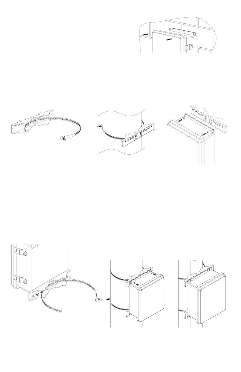
Wall Mount Installation
1- Place unit at desired location and secure with mounting
screws (not included) (Fig. 5, pg. 8).
Fig. 5
Pole Mounting Using Optional Pole Mount Kit PMK1 (not included):
This installation should be made by qualified service personnel. This product contains no serviceable parts.
PMK1 is intended for use with Altronix outdoor rated power supplies or accessories housed in WP1, WP2, WP3
and WP4 enclosures. Brackets are designed for use with the Wormgear Quick Release Straps (two included).
1. Thread one (1) wormgear quick release strap through the slots on the back of a mounting bracket (Fig. 6, pg. 8).
2. Once the desired height of the top Pole Mount bracket is achieved, tighten the straps down by sliding open
end of the strap through the locking mechanism on the strap, then tighten the screw with
flat head screwdriver or 5/16” hex socket driver (Fig. 7, pg. 8 and Fig. 9, pg. 8).
Fig. 8
Fig. 10a
5” (127mm) square pole
Fig. 9
Fig. 7
Fig. 10
2” to 8”(50.8mm to 203.2mm)
diameter round pole
Fig. 6
3. Attach the bottom bracket to the enclosure by inserting bolts through the flange of the enclosure and into the
bracket, tightening bolts with a 7/16” hex socket (Fig. 8, pg. 8).
4. Thread the second wormgear quick release strap through the slots on the back of the bottom mounting bracket
(Fig. 6, pg. 8).
5. Mount enclosure onto the top bracket by inserting bolts through flange of the enclosure and into the bracket,
tightening bolts with a 7/16” hex socket (Fig. 8, pg. 8).
6. Tighten the straps of the bottom bracket down by sliding the open end of the strap through the locking
mechanism on the strap, then tighten screw with flat head screwdriver or 5/16” hex socket driver
(Fig. 6, pg. 8).
7. Clip excess straps.
- 8 - NetWaySP4 Series
Page 9

1.40”
(
)
(
)
(
)
(36mm)
NetWaySP8X
Mechanical Drawing and Dimensions (H x W x D approx.):
13.5” x 13” x 3.25” (342.9mm x 330.2mm x 82.6mm)
1.20”
(31mm)
0.75”
(19mm)
1.40”
(36mm)
4.85”
(123mm)
12.5”
(318mm)
11.0”
(279mm)
4.85”
(123mm)
(36mm)
1.40”
0.75”
(19mm)
1.20”
(31mm)
0.9375”
(24mm)
3.25”
(83mm)
1.20”
(31mm)
1.40”
(36mm)
5.10”
(130mm)
5.10”
(130mm)
3.25”
(83mm)
(330mm)
1.0”
(25mm)
5.10”
(130mm)
13.0”
6.5625”
(167mm)
0.9375”
(24mm)
3.25”
(83mm)
3.25”
(83mm)
1.0”
(25mm)
1.0”
25mm
10.5”
267mm
25mm
1.0”
- 9 - NetWaySP4 Series
Page 10
NetWaySP8PL
Mechanical Drawing and Dimensions (H x W x D approx.):
10.75” x 8.875” x 2.375” (273.1mm x 225.4mm x 60.3mm)
8.875” (225.4mm)
8.25” (209.5mm)
0.25”
(6.4mm)
10.25”
(260.3mm)
10.75”
(273.1mm)
- 10 - NetWaySP4 Series
Page 11
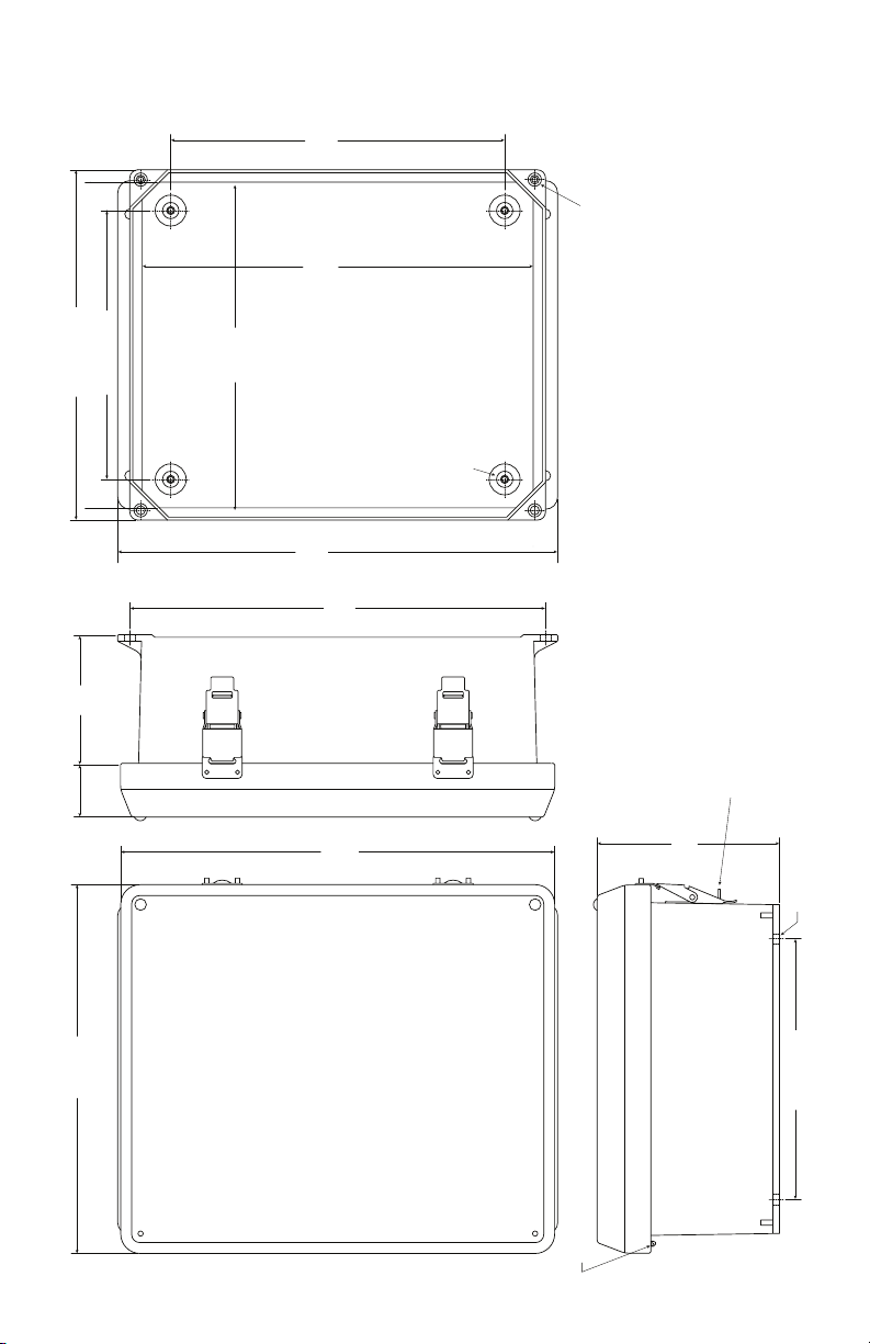
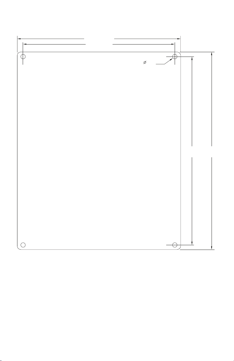
NetWaySP8WP and NetWaySP8WPN
Mechanical Drawing and Dimensions (H x W x D approx.):
13.31” x 11.31” x 5.59” (338.1mm x 287.3mm x 142mm)
10.25”
(260.4mm)
10-32 X 0.25” (6.4mm)
8.25” (209.6mm)
10.75” (273.1mm)
10.00”
(254mm)
12.00”
(304.8mm)
13.50”
(342.9mm)
12.75”
(323.9mm)
10-32 X 0.375” (9.6mm)
BRASS INSERT (X4)
BRASS INSERT (X2)
3.96”
(100.6mm)
PADLOCK LATCH ATTACHED WITH RIVETS
1.61”
(40.9mm)
11.31”
13.31”
(338.1mm)
(287.3mm)
STAINLESS STEEL PIANO HINGE
(Ø 0.375” (9.5mm) PADLOCK EYE).
5.59”
(142mm)
- 11 - NetWaySP4 Series
Ø 0.32 (8.1mm) MOUNTING HOLE
TYP. 4 PLACES
8.00” (203.2mm)
Page 12

FRONT VIEW COVER REMOVEDRIGHT SIDE VIEWFRONT VIEW
END VIEW
SECTION A-A
AA
316 STAINLESS STEEL
PADLOCK LATCH ATTACHED
WITH RIVETS. Ø.375 PADLOCK EYE
17.36”
441 mm
12.00”
304.8mm
6.41”
162.8mm
10-32 X .250
BRASS INSERT
4 PLCS.
14.54” (369.3mm)
16.74”
425.2mm
0.125” (3.2mm)
14.25”
362mm
14.00” (355.6mm)
12.23” (310.6mm)
17.53”
445.3mm
16.00”
406.4mm
1.67”
42.4mm
5.00”
127mm
16.73”
425mm
15.3”
388.6mm
6.67”
169.4mm
4.94”
125.5mm
5.77”
146.6mm
0.75”
19.1mm
MOUNTING PLATE
Ø.32” (8.1mm)
WALL MOUNTING HOLE X 4
NetWaySP8WPX
Mechanical Drawing and Dimensions (H x W x D approx.):
17.53” x 15.3” x 6.67” (445.3mm x 388.6mm x 169.4mm)
Altronix is not responsible for any typographical errors.
140 58th Street, Brooklyn, New York 11220 USA | phone: 718-567-8181 | fax: 718-567-9056
website: www.altronix.com | e-mail: info@altronix.com | Lifetime Warranty | Made in U.S.A.
IINetWaySP8 Series E09R
- 12 - NetWaySP4 Series
MEMBER
 Loading...