

Page 1
802.3bt Media Converter/Injectors
Models include:
NetWaySP1BT
- 802.3bt Media Converter/Injector
- Modular plastic case.
NetWaySP1BTWPN
- 802.3bt Media Converter/Injector.
- NEMA4/4X rated outdoor enclosure.
Installation Guide
NetWaySP1BTWP
- 802.3bt Media Converter/Injector with
Integral Power.
- NEMA4/4X rated outdoor enclosure.
NetWaySP1BTWPX
- 802.3bt Media Converter/Injector with
Integral Power.
- NEMA4/4X rated outdoor enclosure.
- Accommodates up to four (4)
12VDC/4AH batteries.
DOC#: NetWaySP1BT Rev. 120519
More than just power.
TM
Page 2

Table of Contents:
Overview .................................................................................................pg. 3
Features .......................................................................pg. 3
Recommended Altronix SFP Modules ..............................................pg. 3
Installation Instructions ..........................................................pg. 4
Installation ...................................................................pg. 4
Power Connection .............................................................pg. 4
Input/Data Connections .........................................................pg. 5
Typical Application .............................................................pg. 6
Technical Specifications ..........................................................pg. 6
Wall Mount Installation. . . . . . . . . . . . . . . . . . . . . . . . . . . . . . . . . . . . . . . . . . . . . . . . . . . . . . . . . . pg. 8
Mechanical Drawing and Dimensions ..............................................pg. 9-12
- 2 - NetWaySP1BT Series
Page 3

Altronix NetWaySP1BT Series 802.3bt media converter/injectors provide a single 802.3bt (4PPoE) port up to
90W and accommodate Fiber (1000Base-X/SX/LX) or structured cable to transmit data. Units can be deployed
with structured cable, conventional single/multimode fiber or composite cable (fiber + copper combined).
Cameras/edge devices may be located up to 100m from the unit.
Features:
Overview:
Agency Listings:
• CE European Conformity.
Input:
NetWaySP1BT, NetWaySP1BTWPN:
• 48-56VDC @ 1.9A (95W).
NetWaySP1BTWP, NetWaySP1BTWPX:
• 115VAC, 60Hz, 2.5A or 230VAC, 50/60Hz, 1.3A.
Fiber Port:
• One (1) 1Gb SFP port.
See below for recommended SFP modules.
PoE Port:
• Single port rated up to 90W max.
• IEEE 802.3af, 802.3at and 802.3bt compliant.
Data Port:
• Connectivity: RJ45, auto-crossover.
• Wire type: 4-pair CAT5e and higher.
• Speed: 10/100/1000 Mbps.
• Distance: up to 100m.
Battery Backup
(NetWaySP1BTWP and NetWaySP1BTWPX):
• Built-in charger for sealed lead acid or
gel type batteries.
• Automatic switch over to stand-by battery
when AC fails.
Environmental:
• Refer to Environmental Conditions on page 5.
LED Indicators (Refer to Fig. 4, Pg. 4):
• Yellow and Green LEDs (RJ45 jacks):
Yellow (left) LED: 10/100 Mbps.
Green (right) LED: 1000 Mbps.
• Green PoE LEDs:
Indicate PoE present.
• Green SFP (Fiber) LED:
Indicates SFP connection.
Mechanical:
NetWaySP1BT:
• Modular plastic case.
3.375” x 3.8” x 1” (85.7mm x 96.5mm x 25.4mm).
NetWaySP1BTWPN:
• NEMA4/4X, IP66 Rated enclosure for outdoor use.
• Dimensions (H x W x D approx.):
9.5” x 7.32” x 4.92” (241.3mm x 185.9mm x 125mm)
NetWaySP1BTWP:
• NEMA4/4X, IP66 Rated enclosure for outdoor use.
• Dimensions (H x W x D approx.):
13.31” x 11.31” x 5.59”
(338.1mm x 287.3mm x 142mm).
NetWaySP1BTWPX:
• NEMA4/4X, IP66 Rated enclosure for outdoor use.
• Accommodates four (4) 12VDC/4AH batteries
(48V of backup).
• Dimensions (H x W x D approx.):
17.53” x 15.3” x 6.67”
(445.3mm x 388.6mm x 169.4mm).
Altronix P1MM, P1SM10, P1AB2K and P1GCE are hot-pluggable SFP fiber transceiver modules and are readily
Recommended Altronix SFP Modules:
usable with all Altronix Spectrum fiber optic equipment for 1Gb transmission rates.
P1MM - For use with Multi-Mode Fiber for distances up to 550m.
P1SM10 - For use with Single-Mode Fiber for distances up to 10km.
P1AB2K - For use with Single Strand Single-Mode Fiber for distances up to 2km.
P1GCE - For use with CAT5e or better for distances up to 100m.
NetWaySP1BT Series - 3 -
Page 4
Wiring methods shall be in accordance with the National Electrical Code/NFPA 70/ANSI, and with all local
NetWaySP1BT
802.3bt Converter/Injector
Input: 48–56VDC
Output: IEEE 802.3bt (90W)
48-56VDC
-- Input +
48-56VDC
-- Input +
802.3bt
Output
Data
Port
Fiber
Signal
PoE
SignalSFP
Installation Instructions:
codes and authorities having jurisdiction. All units should be installed by a trained service personnel.
Installation:
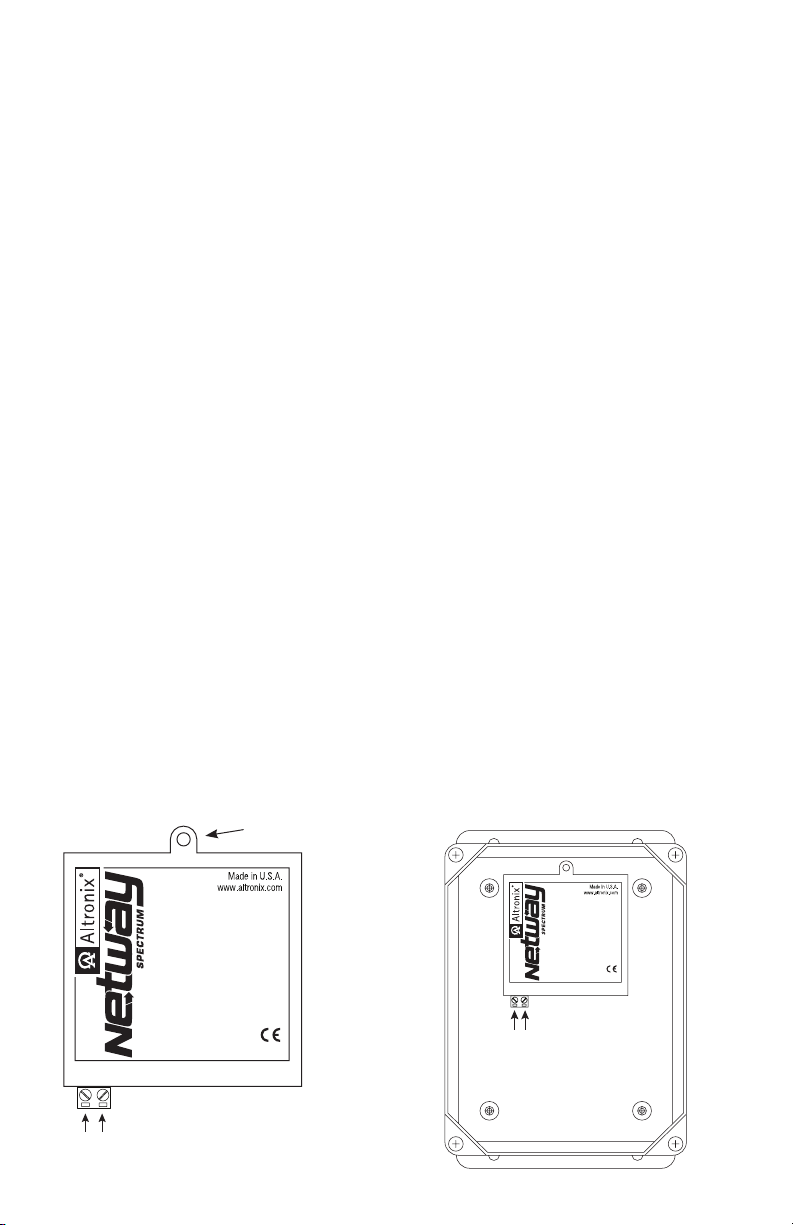
NetWaySP1BT:
1. Mount NetWaySP1BT in desired location utilizing the mounting hole (Fig. 1a, pg. 4). Use a proper fastener
and/or wall anchor when securing NetWaySP1BT with screw through its mounting hole to the wall.
NetWaySP1BTWPN, NetWaySP1BTWP, NetWaySP1BTWPX:
2. Remove backplane from enclosure prior to drilling. Do not discard hardware.
Note: Make sure that hardware will not interfere with components of the circuit board.
3. Mark and drill desired inlets on the enclosure to facilitate wiring. Maximum NEMA type 4X rated fittings
to be used are 0.5”. Follow manufacturer’s specifications for the appropriate size opening.
Note: Inlets for conduit fittings should only be made on the bottom of the enclosure.
To facilitate wire entry utilize weather-tight NEMA rated connectors (supplied), bushings, and cable.
4. Clean out the inside of enclosure before remounting circuit boards/backplane.
5. Mounting NEMA4/4X rated enclosure (Enclosure Dimensions, pg. 10, 11, 12):
Wall mount: Mount unit in desired location. Mark and drill holes to line up with the top and bottom
hole of the enclosure flange. Secure enclosure with appropriate fasteners (e. g. screws
and anchors; bolts and locking nuts, etc.) that are compatible with mounting surface and
are of sufficient length/construction to ensure a secure mount (Fig. 6, pg. 8).
Pole Mount: Refer to Fig. 7 - 11, pg. 8.
6. Mount backplane in enclosure with hardware.
Power Connection:
NetWaySP1BT, NetWaySP1BTWPN:
1. Use external 48-55V UL Listed ITE power supply, carefully observing correct polarity (Fig. 1, 2, pg. 4).
NetWaySP1BTWP, NetWaySP1BTWPX:
Before powering unit, set input voltage selection switch to proper Input Voltage position (Fig. 3a, pg. 4).
Units are factory set for 115VAC.
2. Connect AC power from overcurrent protective device circuit breaker
(20A @ 115VAC, 60Hz or 16A @ 230VAC, 50/60Hz) to the terminals marked [L, N] on power supply
board (Fig. 3, pg. 5). Connect ground lug to earth or green branch wire on backplane (12AWG min.).
Use 14AWG or larger for all power connections (Battery, DC output, AC input).
Keep power-limited wiring separate from non power-limited wiring by utilizing separate knockouts/
inlets. Minimum 0.25” spacing must be provided.
CAUTION: Do not touch exposed metal parts. Shut branch circuit power before installing or servicing
equipment. There are no user serviceable parts inside. Refer installation and servicing to qualified
service personnel.
3. Battery Backup (if desired): Connect four (4) 12VDC batteries wired in series to terminals marked
[– BAT +] (Fig. 3, pg. 5), carefully observing polarity.
When use of stand-by batteries is desired, they must be lead acid or gel type.
Note: When batteries are not used, a loss of AC will result in the loss of output voltage.
Fig. 1 Fig. 1a Fig. 2
NetWaySP1BT
802.3bt Converter/Injector
Input: 48–56VDC
Output: IEEE 802.3bt (90W)
48-56VDC
802.3bt
-- Input +
Output
48-56VDC
-- Input +
- 4 - NetWaySP1BT Series
PoE
Signal SFP
Data
Port
Fiber
Signal
Page 5

Fig. 3
Input Voltage
Selection Switch
115VAC 230VAC
115VAC 230VAC
Fig. 3a
5A 250VA
LGN
--- DC +- BAT +
Ground
To Stand-by
Batteries
48-56VDC
-- Input +
NetWaySP1BT
802.3bt Converter/Injector
Input: 48–56VDC
Output: IEEE 802.3bt (90W)
802.3bt
PoE
Output
Signal SFP
Data
Port
Fiber
Signal
Ground
Input/Data Connections:
1. Connect structured cable from port marked [Data Port] on NetWaySP1BT to a PoE midspan/endspan
(Fig. 4, pg. 5).
2. Connect fiber optic cable to a fiber SFP module. Connect the module to the port marked [SFP] on the
NetWaySP1BT. Connect the other end of fiber cable to an SFP module of a remote device.
SFP LED will illuminate indicating data connection (Fig. 4, pg. 5).
3. Using 4-pair CAT5e or higher cable connect PoE load device to be powered to the port marked
[802.3bt Output] on NetWaySP1BT. After authentication and classification have been established,
[PoE Signal] LED will illuminate indicating PoE presence.
Fig. 4
IEEE 802.3af, 802.3at and 802.3bt
compliant port rated up to 90W max
Yellow LED
10/100 Mbps
48VDC to 56VDC
Input
48-56VDC
– Input +
-- +
802.3bt
Output
PoE
Signal
Data
Port
SFP
Green LED 1000 Mbps
Ethernet Data Port
One (1) Gb SFP port
for Fiber
Fiber
Signal
SFP LED Indicates
data connection
PoE LED indicates PoE present
NetWaySP1BT Series - 5 -
Page 6

Fig. 5
Typical Application:
Factory connected to
power supply
PoE+ (90W) PTZ Data from Midspan/Endspan
CAT5e/6 CAT5e/6
Parameter Description
Ports
Input Power
Requirements
Indicators
Evironmental
Conditions
Regulatory
Compliance
One (1) 1Gb SFP port, one (1) Data port.
One (1) IEEE 802.3af, 802.3at and 802.3bt compliant output port rated up to 90W max.
NetWaySP1BT and NetWaySP1BTWPN:
48-56VDC @ 1.9A (95W).
NetWaySP1BTWP and NetWaySP1BTWPX:
115VAC, 60Hz, 2.5A or 230VAC, 50/60Hz, 1.3A.
Yellow and Green LEDs (RJ45 jacks): IP Link status, 10/100/1000 Base-T/active.
PoE Green LED: Indicates PoE present.
Fiber Signal Green LED: Indicates SFP connection.
Temperature:
NetWaySP1BT:
Operating (90W): – 40ºC to 75ºC (– 40ºF to 167ºF).
Storage: – 40ºC to 75ºC (– 40ºF to 167ºF).
NetWaySP1BTWPN, NetWaySP1BTWP, NetWaySP1BTWPX:
Operating:
60W: – 40ºC to 75ºC (– 40ºF to 167ºF).
80W: – 40ºC to 70ºC (– 40ºF to 158ºF).
90W: – 40ºC to 60ºC (– 40ºF to 140ºF).
Storage: – 40ºC to 85ºC (– 40ºF to 185ºF).
Relative Humidity: 85% +/–5%.
Operating Altitude: – 304.8 to 2,000m.
48-56VDC
-- Input +
NetWaySP1BT
802.3bt Converter/Injector
Input: 48–56VDC
Output: IEEE 802.3bt (90W)
802.3bt
Data
PoE
Output
Port
Signal SFP
NetWaySP1BT
Converts Ethernet or Fiber to
802.3bt PoE port
Fiber
Signal
Fiber
Technical Specifications:
CE European Conformity.
NetWaySP1BT: Product: 10.5 lb. (4.76 kg) | Shipping: 11.9 lb. (5.4 kg).
Weights (approx.)
NetWaySP1BTWPN: Product: 3.7 lb. (1.68 kg) | Shipping: 5 lb. (2.27 kg).
NetWaySP1BTWP: Product: 10.5 lb. (4.76 kg) | Shipping: 11.9 lb. (5.4 kg).
NetWaySP1BTWPX: Product: 15 lb. (6.8 kg) | Shipping: 17.5 lb. (7.9kg).
- 6 - NetWaySP1BT Series
Page 7

Notes:
NetWaySP1BT Series - 7 -
Page 8
Wall Mount Installation:
1- Place unit at desired location and secure with mounting
screws (not included) (Fig. 6, pg. 8).
Fig. 6
This installation should be made by qualified service personnel. This product contains no serviceable parts.
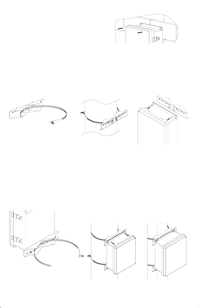
Pole Mounting Using Optional Pole Mount Kit PMK1:
PMK1 outdoor pole mount kits is designed to simplify the installation of Altronix outdoor rated power supplies
and accessories housed in models WP1, WP3 and WP4 NEMA rated enclosures. PMK1 can be mounted on 2”
to 8” (50.8mm to 203.2mm) diameter round or 5” (127mm) square poles. Brackets are designed for use with the
Wormgear Quick Release Straps (two included).
1. Thread one (1) wormgear quick release strap through the slots on the back of a mounting bracket (Fig. 7, pg. 8).
2. Once the desired height of the top Pole Mount bracket is achieved, tighten the straps down by sliding open
end of the strap through the locking mechanism on the strap, then tighten the screw with
flat head screwdriver or 5/16” hex socket driver (Fig. 8, pg. 8 and Fig. 10, pg. 8).
Fig. 7
3. Attach the bottom bracket to the enclosure by inserting bolts through the flange of the enclosure and into the
bracket, tightening bolts with a 7/16” hex socket (Fig. 9, pg. 8).
4. Thread the second wormgear quick release strap through the slots on the back of the bottom mounting bracket
(Fig. 7, pg. 8).
5. Mount enclosure onto the top bracket by inserting bolts through flange of the enclosure and into the bracket,
tightening bolts with a 7/16” hex socket (Fig. 9, pg. 8).
6. Tighten the straps of the bottom bracket down by sliding the open end of the strap through the locking
mechanism on the strap, then tighten screw with flat head screwdriver or 5/16” hex socket driver
(Fig. 7, pg. 8).
7. Clip excess straps.
Fig. 8
Fig. 9
Fig. 11
2” to 8”(50.8mm to 203.2mm)
Fig. 10
- 8 - NetWaySP1BT Series
diameter round pole
Fig. 11a
5” (127mm) square pole
Page 9

NetWaySP1BT
Mechanical Drawing and Dimensions (W x L x H approx.):
3.375” x 3.8” x 1” (85.7mm x 96.5mm x 25.4mm)
NetWaySP1BT Series - 9 -
Page 10
4.25” 108mm
6.0” 152.4mm
6.75” 171.5mm
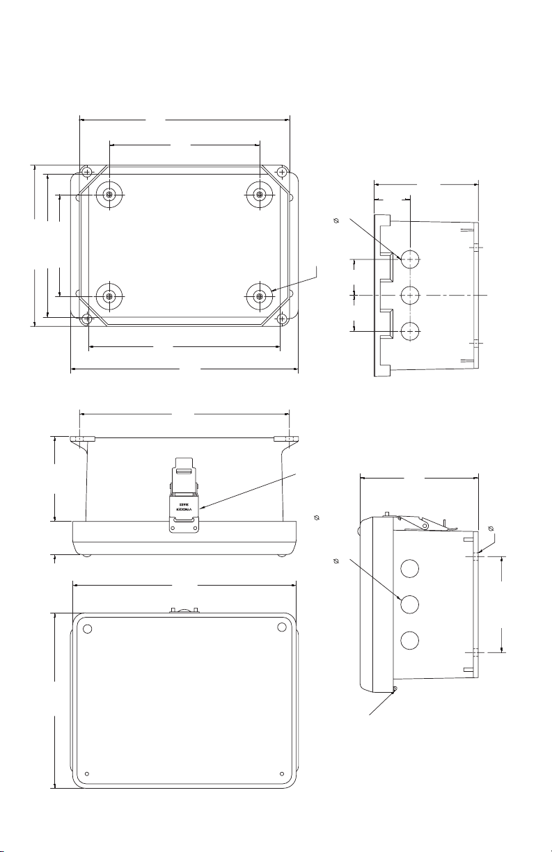
NetWaySP1BTWPN
Mechanical Drawing and Dimensions (H x W x D approx.):
9.5” x 7.32” x 4.92” (241.3mm x 185.9mm x 125mm)
8.75”
222.2mm
6.27”
159.3mm
4.35”
38mm
110.5mm
8.0”
203.2mm
9.5”
8.75”
222.2mm
241.3mm
1.5”
0.65” (16.5mm) three (3) 5/8” wiring inlets
on NetWay1DWPH and NetWay1DWPMH (only)
4 Places
10-32 X 0.25” (6.4mm)
1.5”
38mm
1.5”
38mm
Piano Hinge
4.92”
125mm
3.54”
89.9mm
1.38”
35.1mm
9.32”
236.7mm
7.32”
185.9mm
- 10 - NetWaySP1BT Series
316 Stainless Steel
Padlock Latch Attached
0.375” (9.5mm) Padlock Eye
0.65” (16.5mm) three (3) 5/8” wiring inlets
on NetWay1DWPH and NetWay1DWPMH (only)
304 Stainless Steel
4 Places
0.312” (7.9mm) TYP
4.0” 101.6mm
Page 11

NetWaySP1BTWP
Enclosure Drawing and Dimensions (H x W x D approx.):
13.31” x 11.31” x 5.59” (338.1mm x 287.3mm x 142mm)
10.25”
(260.4mm)
10-32 X 0.25” (6.4mm)
BRASS INSERT (X2)
8.25” (209.6mm)
10.75” (273.1mm)
3.96”
(100.6mm)
10.00”
(254mm)
12.00”
13.50”
(342.9mm)
(304.8mm)
12.75”
(323.9mm)
10-32 X 0.375” (9.6mm)
BRASS INSERT (X4)
PADLOCK LATCH ATTACHED WITH RIVETS
1.61”
(40.9mm)
11.31”
13.31”
(338.1mm)
(287.3mm)
STAINLESS STEEL PIANO HINGE
(Ø 0.375” (9.5mm) PADLOCK EYE).
5.59”
(142mm)
NetWaySP1BT Series - 11 -
Ø 0.32 (8.1mm) MOUNTING HOLE
TYP. 4 PLACES
8.00” (203.2mm)
Page 12
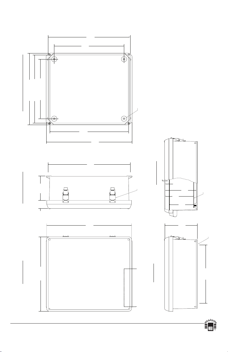
FRONT VIEW COVER REMOVEDRIGHT SIDE VIEWFRONT VIEW
END VIEW
SECTION A-A
AA
316 STAINLESS STEEL
PADLOCK LATCH ATTACHED
WITH RIVETS. Ø.375 PADLOCK EYE
17.36”
441 mm
12.00”
304.8mm
6.41”
162.8mm
10-32 X .250
BRASS INSERT
4 PLCS.
14.54” (369.3mm)
16.74”
425.2mm
0.125” (3.2mm)
14.25”
362mm
14.00” (355.6mm)
12.23” (310.6mm)
17.53”
445.3mm
16.00”
406.4mm
1.67”
42.4mm
5.00”
127mm
16.73”
425mm
15.3”
388.6mm
6.67”
169.4mm
4.94”
125.5mm
5.77”
146.6mm
0.75”
19.1mm
MOUNTING PLATE
Ø.32” (8.1mm)
WALL MOUNTING HOLE X 4
NetWaySP1BTWPX
Mechanical Drawing and Dimensions (H x W x D approx.):
17.53” x 15.3” x 6.67” (445.3mm x 388.6mm x 169.4mm)
Altronix is not responsible for any typographical errors.
140 58th Street, Brooklyn, New York 11220 USA | phone: 718-567-8181 | fax: 718-567-9056
website: www.altronix.com | e-mail: info@altronix.com | Lifetime Warranty | Made in U.S.A.
IINetWaySP1BT Series L05S
- 12 - NetWaySP1BT Series
MEMBER
 Loading...