

Page 1

Media Converters
Installation Guide
Models Include:
NetWaySP8A
- 8-Port Media Converter/Repeater
NetWaySP16A
- 16-Port Media Converter/Repeater
DOC#: NETSP8A_16A Rev. 060517
More than just power.
TM
Page 2
Altronix NetWaySP8A and NetWaySP16A media converter/repeaters convert a 10/100/1000 Mbps to Fiber
(1000Base-X/SX/LX).
Features:
Overview:
Agency Listings:
• UL/cUL UL 60950-1 (Information
Technology Equipment).
• CE European Conformity.
Input:
NetWaySP8A: 115VAC, 60Hz, 0.5A or
230VAC, 50/60Hz, 0.3A.
NetWaySP16A: 115VAC, 60Hz, 1.0A or
230VAC, 50/60Hz, 0.5A.
Fiber Ports:
NetWaySP8A:
NetWaySP16A: Sixteen (16) 1Gb SFP ports.
Eight (8) 1Gb SFP ports.
Ethernet:
NetWaySP8A: Eight (8) 10/100/1000 Mbps.
NetWaySP16A: Sixteen (16) 10/100/1000 Mbps.
LED Indicators:
• Ethernet (RJ45):
Green LED = 1Gbps
Yellow/orange LED = 10/100 Mbps.
• Link SFP LED: Indicates SFP connection.
Environmental:
• Refer to Environmental Conditions on page 3.
Dimensions (W x L x H approx.):
1.625” x 19.125” x 8.5”
(41.3mm x 486mm x 216mm).
Wiring methods shall be in accordance with the National Electrical Code (ANSI/NFPA70), local codes, and the
Installation Instructions:
authorities having jurisdiction. NetWaySP8A/NetWaySP16A is not intended to be connected to outside plant
leads. These products are for indoor use only and must be installed within the protected premises.
1. Attach mounting brackets to the unit for rack or wall mount installation (Fig. 3 or 4, pg. 4).
Affix rubber pads to the unit for shelf installation (Fig. 5, pg. 4).
2. Secure the unit in a rack or on a wall, or place unit on a shelf as desired.
Note: The following factors should be taken into consideration when installing these rack mount units:
a. The unit is to be installed in a space where the maximum ambient temperature does not exceed
104ºF (40ºC).
b. Take care to ensure that there is sufficient air flow around the unit and that obstructions do not impede it.
c. When mounting units in a rack, take care to avoid uneven loading which can cause a hazardous condition.
3. Plug the grounded AC line cord (included) into the IEC 320 connector of the unit (Fig. 1d, pg. 2). Plug unit
into a reliable earth grounded socket. When using multiple units, the sum of the individual name plate ratings
should not exceed the supply circuit rating.
Do not connect to a receptacle controlled by a switch.
4. Connect structured cable from port(s) marked [1-8] or [1-16] on NetWaySP8A/16A to the corresponding
input(s) of an UL Listed ethernet switch (Fig. 1c, pg. 2).
5. Connect fiber optic cable to a fiber SFP module. Connect the module to the port(s) marked [SFP1-SFP8],
[SFP1-SFP16] on the NetWaySP8A/16A. Connect the other end of fiber cable to an SFP module of a remote
device (Fig. 1a, pg. 2). SFP LED will illuminate indicating data connection (Fig. 1b, pg. 2).
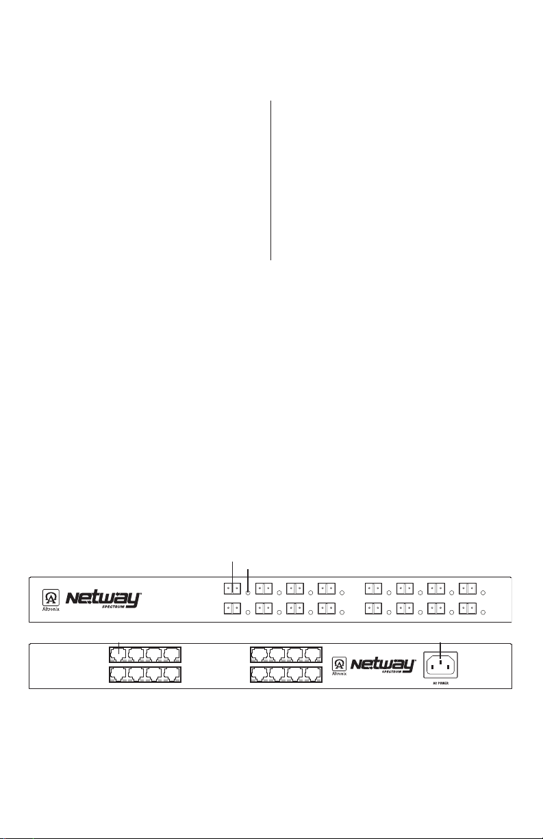
Fig. 1
Front Panel
Rear Panel
1c 1d
1 2 3 4
9 10 11 12
1a
1b
SFP 1 SFP 2 SFP 3 SFP 4 SFP 5 SFP 6 SFP 7 SFP 8
SFP 9 SFP 10 SFP 11 SFP 12 SFP 13 SFP 14 SFP 15 SFP 16
5 6 7 8 5 6 7 8
13 14 15 16
1a 1Gb SFP port.
1b LED indicates fiber link.
1c RJ45 connects to switch
1d IEC 320 Connector: 115/230VAC (grounded line cord included).
- 2 - NetWaySP8A / NetWaySP16A
Page 3

Altronix P1MM and P1SM10 are hot-pluggable SFP fiber transceiver modules and are readily usable with all
Altronix Spectrum fiber optic equipment for 1Gb transmission rates.
P1MM - For use with Multi-Mode Fiber for distances up to 550m.
P1SM10 - For use with Single-Mode Fiber for distances up to 10km.
Typical Application:
Fig. 2
Recommended Altronix SFP Modules:
NetWay Spectrum
Ethernet over Fiber
PoE Switch
or
Media Converter
Data & PoE
30W/60W
Data & PoE
30W/60W
NetWaySP16A - Front Panel
NetWaySP16A - Rear Panel
NetWay Spectrum
Ethernet over Fiber
PoE Switch
or
Media Converter
Fiber from
NetWaySP16A
Fiber from
NetWaySP16A
SFP 1 SFP 2 SFP 3 SFP 4 SFP 5 SFP 6 SFP 7 SFP 8
SFP 9 SFP 10 SFP 11 SFP 12 SFP 13 SFP 14 SFP 15 SFP 16
1 2 3 4
9 10 11 12
Switch
5 6 7 8
13 14 15 16
Technical Specifications:
Parameter Description
Number of Ports
(SFP / Ethernet)
Input Power
Requirements
Environmental
Conditions
Regulatory
Compliance
Weights (approx.)
The lightning flash with arrowhead symbol within an equilateral triangle is intended to alert the user to the presence
of an insulated DANGEROUS VOLTAGE within the product’s enclosure that may be of sufficient magnitude to
constitute an electric shock.
The exclamation point within an equilateral triangle is intended to alert the user to the presence of important operating
and maintenance (servicing) instructions in the literature accompanying the appliance.
NetWaySP8A: Eight (8) Gigabit SFP Ports.
Eight (8) ports 10/100/1000Mbps Ethernet ports.
NetWaySP16A: Sixteen (16) Gigabit SFP Ports.
Sixteen (16) ports 10/100/1000Mbps Ethernet ports.
NetWaySP8A: 115VAC, 60Hz, 0.5A or 230VAC, 50/60Hz, 0.3A.
NetWaySP16A: 115VAC, 60Hz, 1.0A or 230VAC, 50/60Hz, 0.5A.
Operating Ambient Temperature (50W): – 40ºC to 50ºC (– 40ºF to 122ºF)
Relative Humidity: 85%, +/– 5%
Storage Temperature: – 40ºC to 85ºC (– 40ºF to 185ºF).
Operating Altitude: – 304.8 to 2,000m.
UL/cUL Listed for Information Technology Equipment (UL 60950-1)
I.T.E. 43KC
CE European Conformity.
NetWaySP8A: Product: 3.81 lb. (1.72kg) | Shipping: 6.00 lb. (2.72kg)
NetWaySP16A: Product: 4.5 lb. (2.04kg) | Shipping: 6.69 lb. (3.03kg)
115/230VAC Input
CAUTION: To reduce the risk of electric shock do not open enclosure.
There are no user serviceable parts inside. Refer servicing to qualified service personnel.
NetWaySP8A / NetWaySP16A - 3 -
Page 4

Mounting Options:
Rack Mount Installation
1. Remove and discard factory installed screws from both sides of rack chassis (Fig. 3a).
2. Install mounting brackets (A) on the left and right side of rack chassis using the four (4) flat head screws (B)
(included) (Fig. 3b).
3. Place unit into desired EIA 19” rack position and secure with mounting screws (not included) (Fig. 3c).
Fig. 3
Fig. 3a
Fig. 3b
Fig. 3c
Top Top
Front
Left
A
Remove
Front
Left
B
Wall Mount Installation
1. Install mounting brackets (A) on the left and right side of rack chassis using
four (4) flat head screws (B) (included) (Fig. 4a).
2. Place unit at desired location and secure with #6 size screws or larger (not included) (Fig. 4b).
Caution: It is necessary to make sure mounting screws are securely fastened
to a beam when installing the unit vertically.
Fig. 4
Fig. 4a
B
Fig. 4b
A
Top
Front Left
Dotted lines indicate studs behind sheetrock.
Shelf Installation
1- Position and affix rubber pads (C) (included) at each corner on the bottom of the unit (Fig. 5).
2- Place unit in desired location.
Fig. 5
Left Side
C
Rubber
Pad
Altronix is not responsible for any typographical errors.
140 58th Street, Brooklyn, New York 11220 USA | phone: 718-567-8181 | fax: 718-567-9056
website: www.altronix.com | e-mail: info@altronix.com | Lifetime Warranty | Made in U.S.A.
IINetWaySP8A/NetWaySP16A H06R
- 4 - NetWaySP8A / NetWaySP16A
Mounting Hardware (Included):
Two (2) mounting brackets
A
Six (6) flat head screws
B
for mounting brackets.
Four (4) rubber pads.
C
MEMBER
 Loading...