

Page 1

Embedded
Hardened Ethernet over Fiber PoE+ Switch
with Optimized Lithium Iron Phosphate
Battery Charger
Installation Guide
™
Models include:
NetWaySP3LWPX
- Includes one (1) Fiber Optic SFP 1G Link,
3-port PoE+ switch and power supply.
- NEMA4/4X, IP66 rated Outdoor enclosure.
- Accommodates one (1) 12V LiFePO4 battery.
NetWaySP4LWPX
- Includes two (2) Fiber Optic SFP 1G Links,
4-port PoE+ switch and power supply.
- NEMA4/4X, IP66 rated Outdoor enclosure.
- Accommodates one (1) 12V LiFePO4 battery.
DOC#: NetWaySPLWPX Rev. 103118
NetWay4ELWPX
- Includes one (1) Fiber Optic SFP 1G Link,
4-port PoE+ switch and power supply.
- NEMA4/4X, IP66 rated Outdoor enclosure.
- Accommodates one (1) 12V LiFePO4 battery.
NetWaySP8LWPX
- Includes two (2) Fiber Optic SFP 1G Links,
8-port PoE+ switch and power supply.
- NEMA4/4X, IP66 rated Outdoor enclosure.
- Accommodates one (1) 12V LiFePO4 battery.
More than just power.
TM
Page 2

Table of Contents:
Overview .................................................................................................pg. 3
Features .......................................................................pg. 3
Configuration Chart. . . . . . . . . . . . . . . . . . . . . . . . . . . . . . . . . . . . . . . . . . . . . . . . . . . . . . . . . . . . . pg. 3
Enclosure Mounting and Installation ...............................................pg. 4
Installation Instructions ..........................................................pg. 4-5
Port Configurations .............................................................pg. 4
Recommended Altronix SFP Modules ..............................................pg. 5
Configuring Units for Network Connection .........................................pg. 5
Factory Default Settings ........................................................pg. 5
Network Settings ..............................................................pg. 5
Static .......................................................................pg. 5
DHCP .......................................................................pg. 6
Factory Reset Option ............................................................pg. 6
Typical Application Drawings
NetWaySP3LWPX ............................................................pg. 7
NetWaySP4LWPX ............................................................pg. 7
NetWay4ELWPX .............................................................pg. 8
NetWaySP8LWPX ............................................................pg. 8
Wall Mount Installation. . . . . . . . . . . . . . . . . . . . . . . . . . . . . . . . . . . . . . . . . . . . . . . . . . . . . . . . . . pg. 11
Pole Mounting Using Optional Pole Mount Kit ......................................pg. 11
Mechanical Drawings and Dimensions .............................................pg. 12
- 2 - NetWaySPLWPX Series
Page 3

Altronix Hardened Ethernet over Fiber PoE+ Switches with Optimized Lithium Iron Phosphate Battery Charger
provide one (1) or two (2) 1Gb SFP (Fiber) ports, three (3), four (4) or eight (8) PoE (up to 15W) or two (2) PoE+
(up to 30W) ports passing data for PoE/PoE+ compliant devices. Outputs are also configurable for a single Hi-PoE
(60W) port. These units are designed to support a single 12V LiFePO4 (Lithium Iron Phosphate) battery for high
storage and charge/discharge cycle life reliability.
Features:
Overview:
Input:
• 115VAC, 60Hz, 2.5A or 230VAC, 50/60Hz, 1.3A.
Power Output:
• See Configuration Chart below for output ports.
• IEEE 802.3at (30W) and IEEE 802.3af (15W)
compliant.
• 75W total power
(Note: connected devices in total not to exceed 75W).
• Integral surge protection.
Fiber Port:
• One (1) or two (2) Gigabit SFP ports.
• Use with SFP module 1000Base-X (1Gb),
compliant to Class 1 laser product (not included).
Ethernet Ports:
• 10/100/1000 Mbps ports.
• Connectivity: RJ45, auto-crossover.
• Wire type: 4-pair CAT5 or better structured cable.
• Distance: up to 100m.
• Speed: 10/100/1000 Mbps, half/full duplex,
auto negotiation.
Battery Backup:
• Built-in charger for 12V LiFePO4
(Lithium Iron Phosphate) battery.
Caution: Do not use lead acid or gel type batteries.
• Automatic switch over to stand-by battery
when AC fails.
LINQ Technology:
• Remote network management allows for camera/
device reset and monitoring.
• Provides local and/or remote access to critical
information via LAN/WAN.
• Email and Windows Dashboard Alert notifications
report real-time diagnostics.
• Event log tracks history.
LEDs:
• Individual PoE On LEDs for each port.
• Individual IP Link status, 10/100/1000Base-T/active
LEDs for each port.
• ALOS LED indicates fiber connection for SFP port.
• Heartbeat LED indicates proper operation of the unit.
Applications:
• Provides PoE / PoE+ / Hi-PoE for cameras/devices.
Environmental:
• Operating Ambient Temperature:
60W: –40ºC to 75ºC (–40ºF to 167ºF);
75W: –40ºC to 70ºC (–40ºF to 158ºF);
• Relative Humidity: 85%, +/– 5%
• Storage Temperature:
–40ºC to 85ºC (–40ºF to 185ºF).
• Operating Altitude: –304.8 to 2,000m.
Mechanical:
• NEMA4/4X, IP66 Rated enclosure for outdoor use.
• Accommodates one (1) 12V LiFePO4
(Lithium Iron Phosphate) battery.
• Dimensions (H x W x D approx.):
17.53” x 15.3” x 6.67”
(445.3mm x 388.6mm x 169.4mm).
• Product Weight: 15 lbs. (6.8 kg)
• Shipping Weight: 17.5 lbs. (7.9kg)
Accessories:
NetWaySP1A
• Ethernet over Fiber Media Converter/Repeater - for
applications requiring an additional SFP (Fiber) port.
P1MM
• SFP multi-mode transceiver (distances up to 550m).
P1SM10
• SFP single mode transceiver (distances up to 10km).
P1AB2K
• SFP single strand single mode transceiver kit
(distances up to 2km).
P1GCE
• SFP Copper Transceiver for use with CAT5e or
better (distances up to 100m).
PMK2
• Pole Mount Kit for outdoor enclosures.
BTL125
• 12VDC 4.5AH Lithium Iron Phosphate Battery.
Configulration Chart:
Altronix Model Number SFP Ports
NetWaySP3LWPX
NetWaySP4LWPX
NetWay4ELWPX
NetWaySP8LWPX
*Note: Units provide a total of 75W power. Thus, at any time, only one designated port can provide full 60W
output. Please see Port Configurations (pg. 4) for details.
1 3 1
2 4 Up to 2*
1 4 1
2 8 Up to 2*
PoE and PoE+ Ports
(up to 30W)
Hi-PoE Ports
(up to 60W)
NetWaySPLWPX Series - 3 -
Page 4
Wiring methods shall be in accordance with the National Electrical Code/NFPA 70/ANSI, and with all local
LG N
30W 60W
PORT 2
Enclosure Mounting and Installation:
codes and authorities having jurisdiction. All units should be installed by a trained service personnel.
1. Remove backplane from enclosure prior to drilling. Do not discard hardware.
Note: Make sure that hardware will not interfere with components of the circuit board.
2. Mark and drill desired inlets on the enclosure to facilitate wiring. Maximum NEMA type 4X rated fittings
to be used are 0.5”. Follow manufacturer’s specifications for the appropriate size opening.
Note: Inlets for conduit fittings should only be made on the bottom of the enclosure.
UL Listed NEMA type 4X rated conduit connector/hubs shall be used for the appropriate size inlets.
3. Clean out the inside of enclosure before remounting circuit board.
4. Mounting NEMA4/4X rated enclosure (Enclosure Dimensions, pg. 12):
Wall mount: Mount unit in desired location. Mark and drill holes to line up with the top and bottom holes
of the enclosure flange. Secure enclosure with appropriate fasteners (e. g. screws and anchors; bolts and
locking nuts, etc.) that are compatible with mounting surface and are of sufficient length/construction to
ensure a secure mount (Fig. 9, pg. 11).
Pole Mount: Refer to Figs. 10-14, pg. 11.
5. Mount backplane in enclosure with hardware.
6. To facilitate wire entry utilize weather-tight NEMA rated connectors (supplied), bushings, and cable.
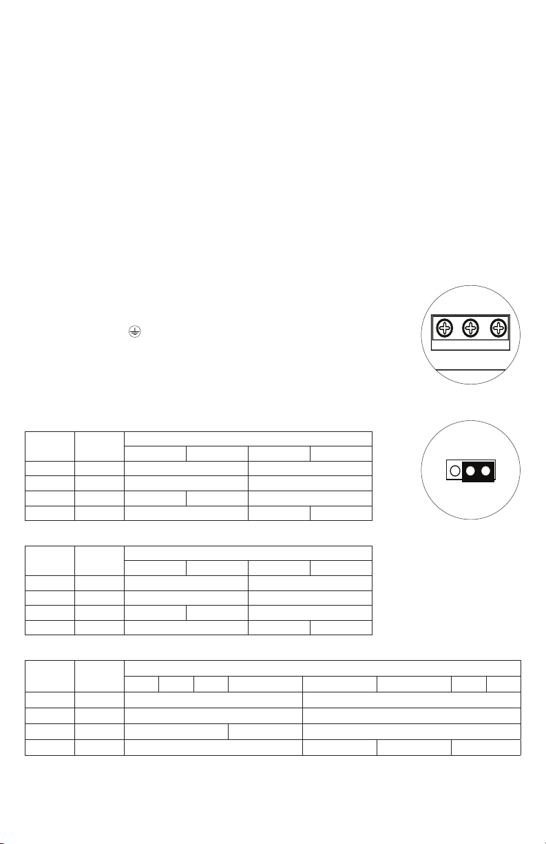
1. Secure cabinet to earth ground. Connect AC power from overcurrent protective
Installation:
device circuit breaker (20A @ 115VAC, 60Hz; 16A @ 230VAC, 50/60Hz) to
the terminals marked [L, N] on power supply board (Fig. 1, pg. 4).
Use 14AWG or larger for all power connections (Battery, DC output, AC input).
Connect ground lug to earth or green branch wire (12AWG min.).
Keep power-limited wiring separate from non power-limited wiring by
utilizing separate knockouts/ inlets. Minimum 0.25” spacing must be provided.
CAUTION: Do not touch exposed metal parts. Shut branch circuit power before
installing or servicing equipment. There are no user serviceable parts inside.
Refer installation and servicing to qualified service personnel.
2. Port Configurations (Fig. 2, pg. 4; Fig. 6a, 7a, 8a, pg. 7-8):
NetWaySP4LWPX
Jumper
Jumper
PORT 2 30W 30W and Data –
PORT 3 30W – 30W and Data
PORT 2 60W Data Only 60W and Data –
PORT 3 60W – 60W and Data Data Only
Position
1 2 3 4
Structured Cable Ports
NetWay4ELWPX
Jumper
PORT 2 30W 30W and Data –
PORT 4 30W – 30W and Data
PORT 2 60W Data Only 60W and Data –
PORT 4 60W – Data Only 60W and Data
Position
1 2 3 4
Jumper
Structured Cable Ports
NetWaySP8LWPX
Jumper
Jumper
PORT 4 30W 30W and Data –
PORT 6 30W – 30W and Data
PORT 4 60W Data Only 60W and Data –
PORT 6 60W – Data Only 60W and Data Data Only
Position
1 2 3 4 5 6 7 8
Structured Cable Ports
Fig. 1
Fig. 2
- 4 - NetWaySPLWPX Series
Page 5

4. Connect structured cables from port marked [Port 1], [Port 2]... on NetWaySP board to PoE compliant
– DC ++ BAT –
To Stand-by
Battery
To Switch
Board
cameras/edge devices (Fig. 5-8, pg. 7-8).
Note: All interconnected devices must be UL Listed.
5. Insert SFP module into port(s) marked [SFP], then connect cable to the SFP module on NetWaySP board
to the corresponding input of an SFP switch (Fig. 5-8, pg. 7-8).
6. Battery Backup (if desired): Connect one (1) 12V LiFePO4
(Lithium Iron Phosphate) battery to terminals marked [+ BAT –]
(Fig. 3, pg. 5), carefully observing polarity.
Use Altronix BTL125 12V/4.5AH Lithium Iron Phosphate battery.
Note: When battery is not used, a loss of AC will result in the
loss of output voltage.
CAUTION: Do not use lead acid or gel type batteries.
7. Please ensure that the cover is secured with security bolt.
Fig. 3
Altronix P1MM, P1SM10, P1AB2K and P1GCE are hot-pluggable SFP fiber transceiver modules and are readily
usable with all Altronix Spectrum fiber optic equipment for 1Gb transmission rates.
P1MM - For use with Multi-Mode Fiber for distances up to 550m.
P1SM10 - For use with Single-Mode Fiber for distances up to 10km.
P1AB2K - For use with Single Strand Single-Mode Fiber for distances up to 2km.
P1GCE - For use with CAT5e or better for distances up to 100m.
Configuring Units for Network Connection
Recommended Altronix SFP Modules:
––––––––––––––––––––––––––––––––––––––––––––––––––––––––––––––––––––––––––––––––––––––––––
Please be sure to visit altronix.com for latest
firmware and installation instructions
––––––––––––––––––––––––––––––––––––––––––––––––––––––––––––––––––––––––––––––––––––––––––
Factory Default Settings
• IP Address: 192.168.168.168
• User Name: admin
• Password: admin
1. Set the static IP address for the laptop to be used for programming to the same network IP address as the
NetwaySP. The default address of the NetwaySP is 192.168.168.168, E.I. 192.168.168.200.
2. Connect one end of the network cable to the network jack on the NetwaySP and the other to the network
connection of the laptop.
3. Open a browser on the computer and enter “192.168.168.168” into the address bar.
A dialog box Authentication Required will appear requesting both user name and password.
Enter the default values here. Click on the button labeled Log In.
4. The status page of the NetWaySP will appear. Click on the tab labeled Network Settings.
This will open the Network Setting screen. In this screen the MAC Address of the NetWaySP module
will be found along with the Network Settings and Email Settings.
Network Settings:
In the IP Address Method field select the method that the IP Address for the NetWaySP will be obtained
(STATIC or DHCP), then follow the appropriate steps.
Static:
A. IP Address: Enter the IP address assigned to the NetWaySP by the network administrator.
B. Subnet Mask: Enter the Subnet of the network.
C. Gateway: Enter the TCP/IP gateway of the network access point (router) being used.
Gateway configuration is required to properly receive emails from the device.
D. HTTP Port: Enter the HTTP port number assigned to the NetWaySP module by the network
administrator to allow remote access and monitoring. The default inbound port setting is 80. HTTP is not
encrypted and unsecure. Even though HTTP can be used for remote access, it is recommended primarily
for use with LAN connections.
E. HTTPS Port: Enter the HTTPS port number assigned to the NetWaySP module by the network
administrator to allow remote access and monitoring. The default inbound port setting is 443.
Being encrypted and more secure, HTTPS is highly recommended for remote access.
F. Click the button labeled Submit Network Settings.
A dialog box will display “New network settings will take effect after the server is rebooted”. Click OK.
NetWaySPLWPX Series - 5 -
Page 6

DHCP:
A. After selecting DHCP in the IP Address Method field click the button labeled Submit Network Settings.
A dialog box will display “New network settings will take effect after the server is rebooted”. Click OK.
Next, click on the button labeled Reboot Server. After rebooting the NetWaySP will be set in the DHCP
mode. The IP address will be assigned by the router when the NetWaySP is connected to the network.
It is recommended to have the assigned IP Address reserved to ensure continued access
(see the network administrator).
B. Subnet Mask: When operating in DHCP, the router will assign the subnet mask values.
C. Gateway: Enter the TCP/IP gateway of the network access point (router) being used.
D. HTTP Port: Enter the HTTP port number assigned to the NetWaySP module by the network administrator
to allow remote access and monitoring. The default inbound port setting is 80. HTTP is not encrypted and
unsecure. Even though HTTP can be used for remote access, it is recommended primarily for use with
LAN connections.
Secure Network Setup (HTTPS):
In order to setup HTTPS for a Secure Network Connection, a Valid Certificate and Key must be used.
Certificates and Key should be in a “.PEM” format. Self Certifications should only be used for testing
purposes as no actual authentication is being performed. In a Self-Certified mode, the connection will still
state that it is unsecure. How to upload Certificate and Key to setup HTTPS:
1. Open Tab Labeled “Security”
2. Select Tab Labeled “Email/SSL”
3. Scroll to bottom under “SSL Settings”
4. Click “Select Certificate”
5. Browse and select valid Certificate to upload from server
6. Click “Select Key”
7. Browse and select valid Key to upload from server
8. Click “Submit Files”
Once the Certificate and Key is uploaded successfully you can proceed with setting up
HTTPS in Network Settings.
A. HTTPS Port: Enter the HTTPS port number assigned to the NetWay4E module by the network
administrator to allow remote access and monitoring. The default inbound port setting is 443.
Being encrypted and more secure, HTTPS is highly recommended for remote access.
B. Click the button labeled Submit Network Settings.
A dialog box will display “New network settings will take effect after the server is rebooted”. Click OK.
Factory Reset Option:
1. Power the unit down. Allow approximately 30 seconds
for the unit to power down completely.
2. Depress Factory Reset button on NetWaySP board while
reapplying power to the unit (Fig. 4, pg. 6).
Continue holding the button until the LEDs on board go
through the start up cycle, then release the button.
Factory Reset
Brooklyn, NY US
www.altronix.com
Altronix Cor
3. The unit returns to the original factory settings.
- 6 - NetWaySPLWPX Series
Factory Reset
NetwaySP4B
Fig. 4
Page 7

Fig. 5
IP PoE/PoE+
or Hi-PoE Device
IP PoE/PoE+
or Hi-PoE Device
Fig. 6
PORT2
Spd: 10/100/1000
PoE: 30W/60W
PoE_Data
PoE_SPR
PORT1
Spd: 10/100/1000
PoE: 30W/60W
PoE_Data
PoE_SPR
Typical Application:
NetWaySP3LWPX
NetwaySP3B
Spd
Link
Altronix Cor
Brooklyn, NY US
www.altronix.com
Spd
Link
Factory Reset
3.3V PWR
Typical Application:
NetWaySP4LWPX
SFP
PORT3 (Uplink)
Spd
Spd: 10/100/1000
Link
PoE: 30W
Input:
48V-56VDC
+
–
From Power Supply
(factory installed)
Fig. 6a
ALOS
Fiber to Switch
IP PoE/PoE+
Device or NetWaySP1A
PoE
IP PoE/PoE+
Device
PoE/PoE+
or Hi-PoE Device
PoE/PoE+
or Hi-PoE Device
PWR
+
–
Input:
48V-56VDC
From Power Supply
(factory installed)
NetwaySP4B
PORT 1
PoE1
PORT 2
PoE2
PORT 3
PoE3
PORT 4
PoE4
IP PoE/PoE+
Device
10/100/1000
60W
PORT 2PORT 3
30W
60W
30W
Altronix Corp.
Brooklyn, NY US
www.altronix.com
60W
Operation
30W
Factory Reset
1000
100
PORT1
PORT2
1000
100
PORT3
SFP2
ALOS
Fiber to the next
Netway Spectrum
SFP Port
Hardened PoE Switch
PORT4
SFP2
ALOS
SFP Port
Fiber to Switch
Note: No limit to quantity of daisy-chained units.
Daisy chaining only limited to total bandwidth of 1Gbps.
NetWaySPLWPX Series - 7 -
Page 8

Fig. 7
Typical Application:
NetWay4ELWPX
NetWay4EB
+ INPUT ---
From Power Supply
(factory installed)
Fig. 8
PoE/PoE+
or Hi-PoE Device
PoE/PoE+
or Hi-PoE Device
Factory Reset
NetwaySP8B
PWR
Fig. 7a
IP PoE/PoE+ Device
PORT 1
PORT 3
PORT 5
SFP
PORT 4
30W 60W
60W
30W
Operation
PORT 2
30W 60W
Typical Application:
NetWaySP8LWPX
PoE1
PoE2
PoE3
PoE4
PORT 2
PORT 4 (1G)
PORT 4PORT 6
PORT 6 (1G)
60W
30W
60W
30W
PORTS 4, 6 = 10/100/1000
PORTS 1, 2, 3, 5, 7, 8 = 10/100
Fig. 8a
60W
Operation
30W
PORT 4
30W / 60W
PORT 3
30W
PORT 2
30W / 60W
PORT 1
30W
1000
100
1000
100
Fiber to Switch
PoE/PoE+
or Hi-PoE Device
IP PoE/PoE+
Device
PoE/PoE+
or Hi-PoE Device
IP PoE/PoE+
Device
PORT1
PORT2
PORT3
PORT4
1000
100
PORT5
1000
100
PORT7
SFP1
ALOS
Fiber to the next
Netway Spectrum
SFP Port
Hardened PoE Switch
PORT6
SFP2
PORT8
ALOS
SFP Port
Fiber to Switch
Factory Reset
From Power Supply
(factory installed)
PORT 8
PORT 7
PoE5
PoE6
PoE7
Input:
+
–
48V-56VDC
PoE8
IP PoE/PoE+ Device
Note: No limit to quantity of daisy-chained units.
Daisy chaining only limited to total bandwidth of 1Gbps.
- 8 - NetWaySPLWPX Series
Page 9

Notes:
- 9 - NetWaySPLWPX Series
Page 10

Notes:
- 10 - NetWaySPLWPX Series
Page 11

Wall Mount Installation
1- Place unit at desired location and secure with mounting
screws (not included) (Fig. 9, pg. 11).
Fig. 9
This installation should be made by qualified service personnel. This product contains no serviceable parts.
Pole Mounting Using Optional PMK2 Pole Mount Kit:
PMK2 outdoor pole mount kit is designed to simplify the installation of Altronix outdoor rated power supplies and
accessories housed in WP2 NEMA rated enclosures. PMK2 can be mounted on 2” to 8” (50.8mm to 203.2mm)
diameter round or 5” (127mm) square poles. Brackets are designed for use with the Wormgear Quick Release
Straps (two included).
1. Thread one (1) wormgear quick release strap through the slots on the back of a mounting bracket (Fig. 10, pg. 11).
2. Once the desired height of the top Pole Mount bracket is achieved, tighten the straps down by sliding open
end of the strap through the locking mechanism on the strap, then tighten the screw with
flat head screwdriver or 5/16” hex socket driver (Fig. 11, pg. 11 and Fig. 13, pg. 11).
Fig. 12
Fig. 14a
5” (127mm) square pole
Fig. 13
Fig. 11
Fig. 14
2” to 8”(50.8mm to 203.2mm)
diameter round pole
Fig. 10
3. Attach the bottom bracket to the enclosure by inserting bolts through the flange of the enclosure and into the
bracket, tightening bolts with a 7/16” hex socket (Fig. 12, pg. 11).
4. Thread the second wormgear quick release strap through the slots on the back of the bottom mounting bracket
(Fig. 10, pg. 11).
5. Mount enclosure onto the top bracket by inserting bolts through flange of the enclosure and into the bracket,
tightening bolts with a 7/16” hex socket (Fig. 12, pg. 11).
6. Tighten the straps of the bottom bracket down by sliding the open end of the strap through the locking
mechanism on the strap, then tighten screw with flat head screwdriver or 5/16” hex socket driver
(Fig. 11, pg. 11).
7. Clip excess straps.
- 11 - NetWaySPLWPX Series
Page 12

FRONT VIEW COVER REMOVEDRIGHT SIDE VIEWFRONT VIEW
END VIEW
SECTION A-A
AA
316 STAINLESS STEEL PADLOCK LATCH
ATTACHED WITH RIVETS. Ø 0.375 PADLOCK EYE
17.36” (441 mm)
12.00” (304.8mm)
6.41” (162.8mm)
10-32 X 0.250 BRASS INSERT 4 PLCS.
14.54” (369.3mm)
16.74” (425.2mm)
0.125” (3.2mm)
14.25” (362mm)
14.00” (355.6mm)
12.23” (310.6mm)
17.53” (445.3mm)
16.00” (406.4mm)
1.67” (42.4mm)
5.00” (127mm)
16.73” (425mm)
15.3” (388.6mm)
6.67” (169.4mm)
4.94” (125.5mm)
5.77” (146.6mm)
0.75” (19.1mm)
MOUNTING PLATE
Ø 0.32” (8.1mm)
WALL MOUNTING HOLE X 4
Mechanical Drawing and Dimensions (H x W x D approx.):
17.53” x 15.3” x 6.67” (445.3mm x 388.6mm x 169.4mm)
Altronix is not responsible for any typographical errors.
140 58th Street, Brooklyn, New York 11220 USA | phone: 718-567-8181 | fax: 718-567-9056
website: www.altronix.com | e-mail: info@altronix.com | Lifetime Warranty | Made in U.S.A.
IINetWaySPLWPX Series F17S
- 12 - NetWaySPLWPX Series
MEMBER
 Loading...