

Page 1
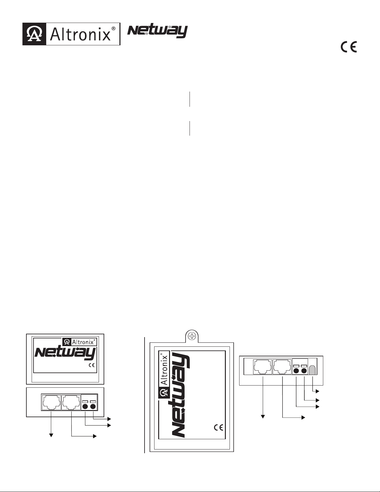
NetWay1512 / NetWay3012 - Adapters
www.altronix.com
IN
OUT
Netway1512
Adapter
12VDC
--- Output +
12VDC
Power to
Camera
+
--
Structured Cable from
NetWay1, NetWay8
or NetWay16
Structured Cable
from IP Camera
www.altronix.com
IN
OUT
Netway3012
Adapter
12VDC
+ Output ---
Power LED
12VDC
Power to
Camera
+
--
Structured Cable
from NetWay8
or NetWay16
Structured Cable
from IP Camera
Overview:
Altronix NetWay1512 and NetWay3012 adapters allow operation of non-PoE compliant fixed and/or PTZ IP cameras with
NetWay midspans.
Specifications:
NetWay1512:
• 12VDC/15W adapter for non-PoE compliant IP cameras.
Common Specifications:
• Power LED indicator.
•
Compact insulated housing.
Installation Instructions:
NetWay1512/NetWay3012 is not intended to be connected to outside plant leads.
NetWay1512 for 12VDC IP cameras up to 15W:
1. Mount NetWay1512 in proximity to IP camera (Fig. 1, pg. 1). Af
and place the second side of the velcro in the desired location.
2. Connect structured cable from port marked [IN] on NetWay1512 to any ports marked [OUT] of NetWay1/NetWay8/
NetWay16 (Fig. 1, pg. 1).
3.
Connect structured cable from port marked [OUT] on NetWay1512 to the IP camera (Fig. 1, pg. 1).
4. Connect 12VDC output from NetWay1512 terminals marked [--- 12VDC +] to the po
IP camera (Fig
5. Power LED indicator will illuminate on NetWay1512 under normal conditions (Fig. 1, pg. 1).
. 1, pg. 1). Polarity must be observed.
NetWay3012:
• 12VDC/30W adapter for non-PoE compliant IP cameras.
• Plug-and-play installation.
fix one side of velcro (supplied) to NetWay1512
wer input of the
NetWay3012 for 12VDC IP fixed or PTZ cameras up to 30W:
1. Mount NetWay3012 in proximity to IP camera utilizing mounting hole (Fig. 2, pg. 1). Use a proper f
wall anchor when securing NetWay3012 to the wall.
2. Connect structured cable from port marked [IN] on NetWay3012 to ports marked [OUT 1 or 2] of NetWay8
or [OUT 1, 2, 9 or 10] of NetWay16 (Fig. 2, pg. 1).
3. Set Power Selector Switch of that corresponding por
t on NetWay8/NetWay16 to 30W (red LED will illuminate)
(Fig. 3a, pg. 2).
4. Connect structured cable from por
t marked [OUT] on NetWay3012 to the IP fixed or PTZ camera (Fig. 2, pg
5. Connect 12VDC output from NetWay3012 terminals marked [---12VDC +] to the power input of the
IP camera (Fig
. 2, pg. 1). Polarity must be observed.
6. Power LED indicator will illuminate on NetWay3012 under normal conditions (Fig. 2, pg. 1).
Fig. 1 Fig. 2
astener and/or
. 1).
Rev. 042109
NetWay1512/NetWay3012 - 1-
Page 2
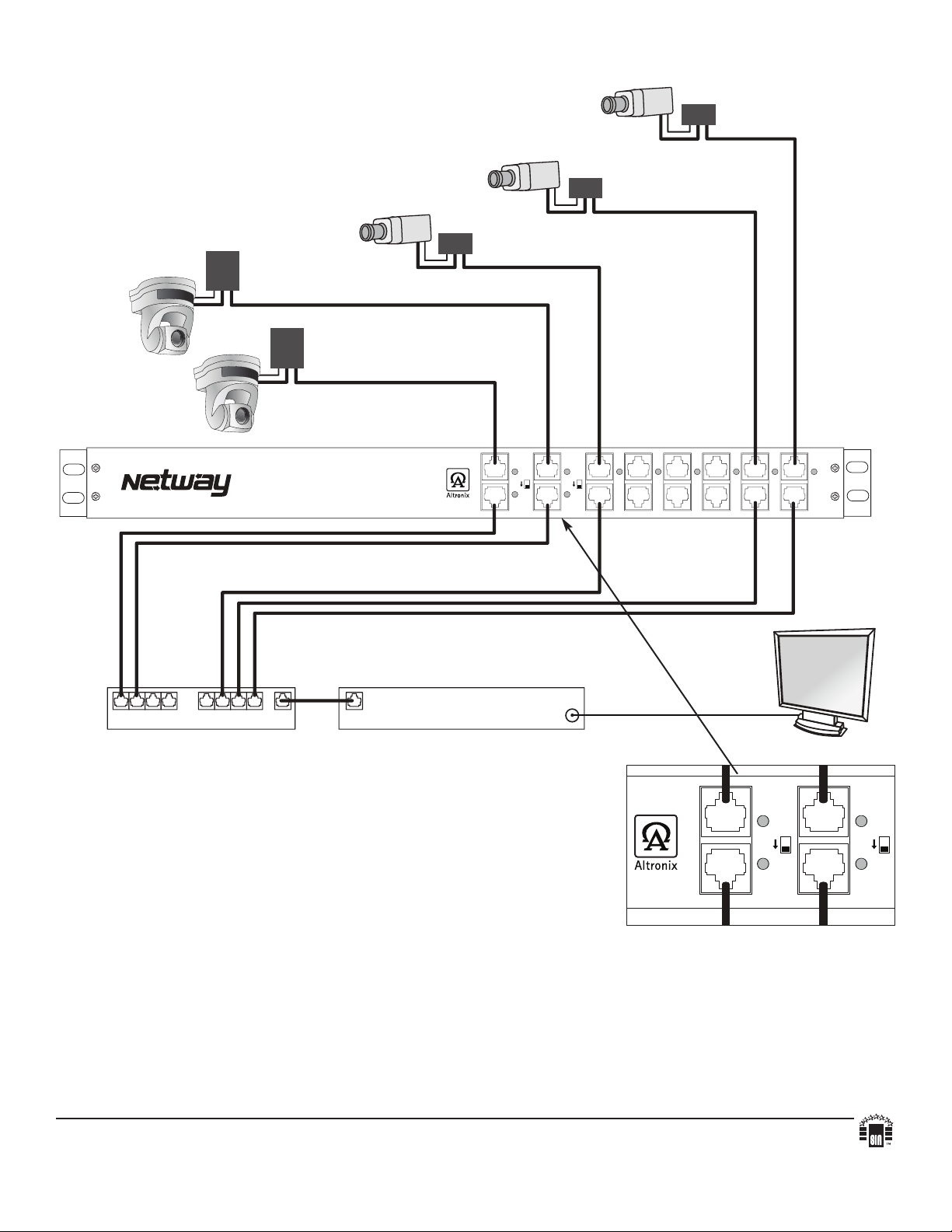
OUT
IN
30W
1 2
30W
3
4567 8
OUT
I
N
Video Monitor
DVR/Video Server
Network Switch
NetWay1512
NetWay3012
12VDC
IP PTZ
NetWay3012
12VDC
IP PTZ
12VDC
IP camera
NetWay1512
12VDC
IP camera
NetWay1512
1
2VDC
IP camera
Fig. 3
OUT
IN
30W
1 2
30W
Typical Application:
Fig. 3a
Altronix is not responsible for any typographical errors.
140 58th Street, Brooklyn, New York 11220 USA, 718-567-8181, fax: 718-567-9056
website: www.altronix.com, e-mail: info@altronix.com, Lifetime Warranty, Made in U.S.A.
IINetWay1512 / NetWay3012 F12I
- 2- NetWay1512/NetWay3012
MEMBER
 Loading...