

Page 1

ALTV2416UL3 Series
CCTV Power Supplies
Installation Guide
Models Include:
• ALTV2416ULX3 • ALTV2416ULCBX3
- 24VAC @ 7 amp (170VA) - 24VAC @ 7 amp (170VA)
or 28VAC @ 6 amp (170VA). or 28VAC @ 6 amp (170VA).
- Sixteen (16) Fuse Protected Outputs. - Sixteen (16) PTC Protected Outputs.
- Factory installed 3-wire linecord. - Factory installed 3-wire linecord.
• ALTV2416300UL3 • ALTV2416300ULCB3
- 24VAC @ 12.5 amp (300VA) - 24VAC @ 12.5 amp (300VA)
or 28VAC @ 10 amp (280VA). or 28VAC @ 10 amp (280VA).
- Sixteen (16) Fuse Protected Outputs. - Sixteen (16) PTC Protected Outputs.
- Factory installed 3-wire linecord. - Factory installed 3-wire linecord.
• ALTV2416300ULM3 • ALTV2416300ULCBM3
- 24VAC @ 12.5 amp (300VA) - 24VAC @ 12.5 amp (300VA)
or 28VAC @ 10 amp (280VA). or 28VAC @ 10 amp (280VA).
- Sixteen (16) Fuse Protected Outputs. - Sixteen (16) PTC Protected Outputs.
- Factory installed 3-wire linecord. - Factory installed 3-wire linecord.
• ALTV2416600UL3 • ALTV2416600ULCB3
- 24VAC @ 25 amp (600VA) - 24VAC @ 25 amp (600VA)
or 28VAC @ 20 amp (560VA). or 28VAC @ 20 amp (560VA).
- Sixteen (16) Fuse Protected Outputs. - Sixteen (16) PTC Protected Outputs.
- Factory installed 3-wire linecord. - Factory installed 3-wire linecord.
Rev. 040506
Page 2
Overview:
These Altronix CCTV Power Supplies provide 24VAC/28VAC distributed via sixteen (16) fuse or PTC protected outputs for powering CCTV Cameras, heaters and other video accessories.
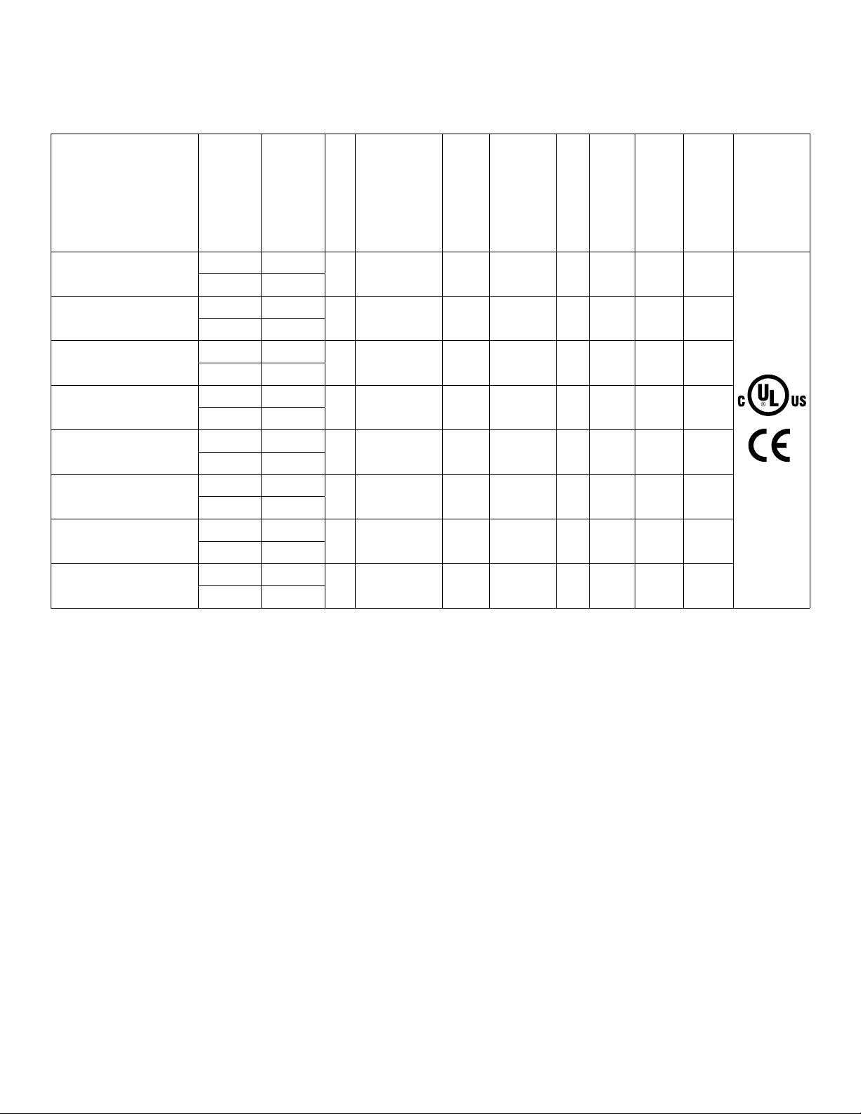
Sixteen (16) Output ALTV2416UL3 Series Reference Chart:
(Class 2
Altronix
power limited
for Dry locations).
(Class 3 for Wet loca-
Model Number
ALTV2416ULX3
ALTV2416ULCBX3
ALTV2416300UL
ALTV2416300ULCB3
ALTV2416300ULM3
ALTV2416300ULCBM3
ALTV2416600UL3
ALTV2416600ULCB3
Output Voltage
24VAC 7 amp 16
28VAC 6 amp
24VAC 7 amp 16
28VAC 6 amp
24VAC 12.5 amp 16
28VAC 10 amp
24VAC 12.5 amp 16
28VAC 10 amp
24VAC 12.5 amp 16
28VAC 10 amp
24VAC 12.5 amp 16
28VAC 10 amp
24VAC 25 amp 16
28VAC 20 amp
24VAC 25 amp 16
28VAC 20 amp
Total Output
Current (Power)
Number of Outputs
PTC Protected
Outputs
------ Yes 3.5 amp
Yes ------ 2.5 amp ------
------ Yes 3.5 amp
Yes ------ 2.5 amp ------
------ Yes 3.5 amp
Yes ------ 2.5 amp ------ ------ ------ 2.7
------ Yes 3.5 amp
Yes ------ 2.5 amp ------
tions).
Fuse Protected Class
1 Outputs
Individual Output
Current (max. per
output not to exceed
Fuse Ratings
total output current).
3.5
amp
3.5
amp
3.5
amp
3.5
amp
Main Fuse
5A/
250V
5A/
250V
15A/
32V
15A/
32V
15A/
32V
15A/
32V
Ratings
Primary In-line
Fuse Ratings
3.5A/
250V
3.5A/
250V
------ 2.7
------ 2.7
------ 2.7
------ 5.4
------ 5.4
115VAC 60Hz
1.8
amp
1.8
amp
amp
amp
amp
amp
amp
amp
Input Current
Agency Listings
Specifications:
• UL Listed for Commercial CCTV Equipment (UL 2044).
CUL Listed - CSA Standard C22.2 No.1-98, Audio,
Video and Similar Equipment.
• Surge suppression.
• AC power LED indicator.
• Power ON/OFF switch
(ALTV2416ULX3, ALTV2416ULCBX3).
• Illuminated power disconnect circuit breaker
with manual reset (all other models).
• Unit maintains camera synchronization.
• Ease of installation saves time & eliminates costly labor.
• Spare fuses included (on fuse protected models).
• Factory installed 3-wire line cord.
Enclosure Dimensions:
ALTV2416300ULM3 and ALTV2416300ULCBM3:
8.5”H x 7.5”W x 3.5”D
ALTV2416ULX3, ALTV2416ULCBX3,
ALTV2416300UL3, ALTV2416300ULCB3,
ALTV2416600UL and ALTV2416600ULCB3:
13.5”H x 13”W x 3.25”D
Installation Instructions:
1. Mount unit in desired location.
2. Set power switch on power distribution board marked [PD] to OFF position for models ALTV2416ULX3 or
ALTV2416ULCBX3 (Figs. 1, 2, pgs. 4, 5). Set power disconnect circuit breaker to OFF position for all
other models (Figs. 3a-8a, pgs. 6-10).
3. All units are factory set for 24VAC operation.
For 28VAC operation, adjust unit prior to mounting and applying power as follows:
Change the wire position so that the wire marked [28V] is connected to the terminal marked [P] and
the wire marked [24V] is connected to the terminal marked [S].
Note: ALTV2416ULCBX3 set for 28VAC operation is not Class 2 Rated, not power limited.
- 2 - ALTV2416UL3series
Page 3

4. Plug-in 3-wire line cord (Figs. 1, 2, pgs. 4, 5).
Keep power limited (PTC protected outputs only) wiring separate from non-power limited wiring.
Minimum .25” spacing must be provided. Use separate knockouts.
5. Set power switch on power distribution board marked [PD] to ON position for models ALTV2416ULX3 or
ALTV2416ULCBX3 (Figs. 1, 2, pgs. 4, 5). Set power disconnect circuit breaker to RESET (ON) position for
all other models (Figs. 3a-8a, pgs. 6-10).
6. Measure output voltage before connecting devices. This helps avoid potential damage.
Terminals marked [1P - 16P] are of the same polarity.
CAUTION: Determine the maximum operating voltage of the equipment being powered before adjusting
the output voltage.
7. Set power switch on power distribution board marked [PD] to OFF position for models ALTV2416ULX3 or
ALTV2416ULCBX3 (Figs. 1, 2, pgs. 4, 5). Set power disconnect circuit breaker to OFF position for all
other models (Figs. 3a-8a, pgs. 6-10).
8. Connect devices to terminals marked [1P - 1N through 8P - 8N] on PD8 board (Figs. 1-4, 7, 8, pgs. 4-7, 9, 10),
or terminals marked [1P - 1N through 16P - 16N] on PD16W/PD16WCB board (Fig. 5, pg. 8), carefully
observing polarity.
9. Set power switch on power distribution board marked [PD] to ON position for models ALTV2416ULX3 or
ALTV2416ULCBX3 (Figs. 1, 2, pgs. 4, 5). Set power disconnect circuit breaker to RESET (ON) position for
all other models (Figs. 3a-8a, pgs. 6-10).
10. Green LED will illuminate when power is present.
11. Upon completion of wiring, secure enclosure door with screws (supplied). Installation of cam lock is optional.
Caution: Equipment to be installed/serviced by authorized/trained personnel only.
Shut branch circuit power before installing/servicing equipment.
WARNING: To reduce the risk of fire or electric shock, do not expose the unit to rain or moisture.
This installation should be made by qualified service personnel and should conform to all local codes
and in accordance with the National Electrical Code. Use 75º C or higher rated UL insulated wiring for
connecting the unit to the mains. Replace fuses only with the same type and rating (refer to Sixteen (16)
Output ALTV2416UL3 Reference Chart, pg. 2)
Terminal Identification:
PD8 - Power Distribution Module
Terminal Legend Function/Description
1P - 8P AC output.
1N - 8N AC output.
PD16W - Power Distribution Module
Terminal Legend Function/Description
1P - 16P AC output.
1N - 16N AC output.
ALTV2416UL3series - 3 -
Page 4
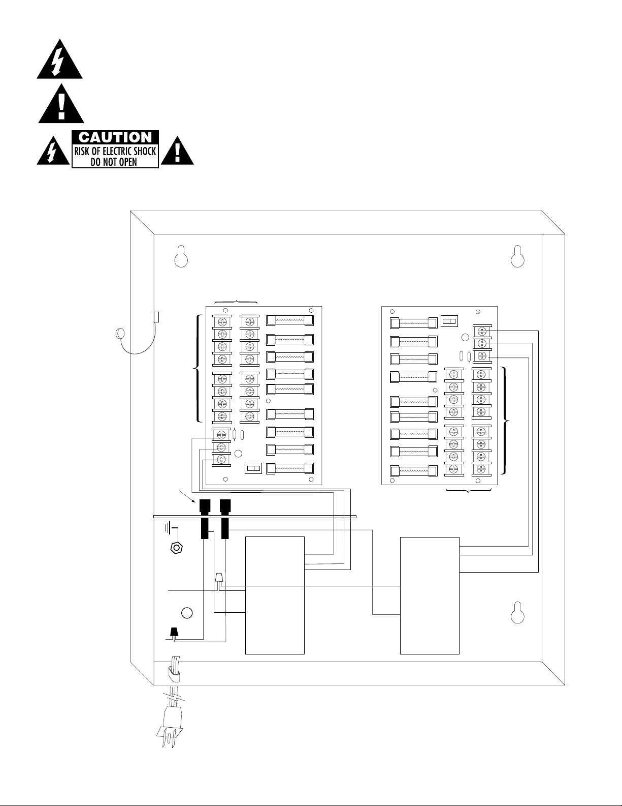
Connected
to Door
115VAC
input,
50/60 Hz.
White
Lead
Black
Lead
XFMR
XFMR
non-power limited
non-power limited
Black
Lead
Ground
N
CO MM ON PO WE R OUT PU TS
P
FU SE D PO WE R OU TP UT S
1 2 3 4 5 6 7 8
D1
INPUT
N P S
R1
LED
N
CO MM ON PO WE R OUT PU TS
P
FU SE D PO WE R OU TP UT S
1 2 3 4 5 6 7 8
D1
INPUT
N P S
R1
LED
ON OFF
ON OFF
MAIN
FUSE
MAIN
FUSE
Primary
In-line
Fuse
Class 1 Outputs
24VAC or 28VAC output 1
(Follow same procedure using
terminals 2P & N through 8P & N
outputs 2 through 8)
24VAC or 28VAC output 1
(Follow same procedure using
terminals 2P & N through 8P & N
outputs 2 through 8)
Class 1
Outputs
The lightning flash with arrow head symbol within an equilateral triangle is intended to alert the user to the
presence of an insulated “DANGEROUS VOLTAGE” within the products enclosure that may be of
sufficient magnitude to constitute an electric shock.
The exclamation point within an equilateral triangle is intended to alert the user to the presence of important
operating and maintenance (servicing) instructions in the literature accompanying the appliance.
Fig. 1
ALTV2416ULX3
CAUTION: To reduce the risk of electric shock do not open enclosure. There are no
user serviceable parts inside. Refer servicing to qualified service personnel.
- 4 - ALTV2416UL3series
Page 5

N
CO MM ON PO WE R OUT PU TS
P
D1
INPUT
N P S
R1
LED
MAIN
FUSE
F1 F 2 F 3 F4 F 5 F6 F7 F 8
SW1
ON OFF
N
CO MM ON PO WE R OUT PU TS
P
D1
INPUT
N P S
R1
LED
MAIN
FUSE
F1 F 2 F 3 F 4 F5 F 6 F 7 F8
SW1
ON OFF
Connected
to Door
115VAC
input,
50/60 Hz.
White
Lead
Black
Lead
XFMR
XFMR
non-power limited
non-power limited
Black
Lead
Ground
Primary
In-line
Fuse
24VAC configuration
Class 2 Not We t/
Class 3 We t
28VAC configuration
Class 1
24VAC or 28V A C
output 1 (Follow same
procedure using terminals 2P & N
through 8P & N outputs 2 through 8)
24VAC or 28V A C
output 1 (Follow same
procedure using terminals 2P & N
through 8P & N outputs 2 through 8)
24VAC
configuration
Class 2 Not Wet/
Class 3 We t
28VAC
configuration
Class 1
Fig. 2
ALTV2416ULCBX3
ALTV2416UL3series - 5 -
Page 6

Black Lead
White Lead
115VAC input
50/60 Hz
XFMR*
Ground
Connected
to Door
non-power limited
non-power limited
N
CO MM ON PO WE R O UT PU TS
P
FU SE D PO WE R OU TP UT S
1 2 3 4 5 6 7 8
D1
INPUT
N P S
R1
LED
N
CO MM ON PO WE R O UT PU TS
P
FU SE D PO WE R OU TP UT S
1 2 3 4 5 6 7 8
D1
INPUT
N P S
R1
LED
MAIN FUSE
MAI N FUS E
Illuminated Power Disconnect
Circuit Breaker with manual reset
Class 1 Outputs
24VAC or 28VAC output 1
(Follow same procedure using
terminals 2P & N through 8P & N
outputs 2 through 8)
24VAC or 28VAC output 1
(Follow same procedure using
terminals 2P & N through 8P & N
outputs 2 through 8)
Class 1
Outputs
Fig. 3
ALTV2416300UL3
Fig. 3a
- 6 - ALTV2416UL3series
Page 7

N
CO MM ON PO WE R O UT PU TS
P
D1
INPUT
N P S
R1
LED
MAIN
FUSE
F1 F2 F 3 F 4 F5 F 6 F 7 F 8
SW1
ON OFF
N
CO MM ON PO WE R O UT PU TS
P
D1
INPUT
N P S
R1
LED
MAIN
FUSE
F1 F2 F 3 F 4 F5 F 6 F7 F 8
SW1
ON OFF
Black Lead
White Lead
115VAC input
50/60 Hz
XFMR*
Ground
Connected
to Door
non-power limited
non-power limited
Illuminated Power Disconnect
Circuit Breaker with manual reset
24VAC configuration
Class 2 Not We t/
Class 3 We t
24VAC or 28V A C
output 1 (Follow same
procedure using terminals 2P & N
through 8P & N outputs 2 through 8)
24VAC or 28VAC
output 1 (Follow same
procedure using terminals 2P & N
through 8P & N outputs 2 through 8)
24VAC
configuration
Class 2 Not We t/
Class 3 We t
Fig. 4
ALTV2416300ULCB3
Fig. 4a
ALTV2416UL3series - 7 -
Page 8

Transformer
underneath
p
ower supply
board
3.5A 250V
For continuous protection against risk of fire
replace fuses with same type and rating.
common
outputs
protected
outputs
P
N
XFMR*
NPS
XF MR In put
12345678
9 10 11 12 13 14 15 16
P N
Illuminated Power Disconnect
Circuit Breaker with manual reset
Fig. 5
Transformer
underneath
p
ower supply
board
Illuminated Power Disconnect
Circuit Breaker with manual reset
P
N
NPS
XF MR In put
common
outputs
protected
outputs
12345678
9 10 11 12 13 14 15 16
NP
ALTV2416300ULM3
Fig. 5a
Fig. 6
ALTV2416300ULCBM3
Fig. 6a
- 8 - ALTV2416UL3series
Page 9

N
CO MM ON PO WE R O UT PU TS
P
FU SE D PO WE R OU TP UT S
1 2 3 4 5 6 7 8
D1
INPUT
N P S
R1
LED
N
CO MM ON PO WE R O UT PU TS
P
FU SE D PO WE R OU TP UT S
1 2 3 4 5 6 7 8
D1
INPUT
N P S
R1
LED
White
Lead
XFMR*
Black
Lead
115VAC input,
50/60 Hz.
Ground
Connected
to Door
non-power limited
non-power limited
non-power limited
MAIN FUSE
MAIN FUSE
Illuminated Power Disconnect
Circuit Breaker with manual reset
Class 1 Outputs
24VAC or 28VAC output 1
(Follow same procedure using
terminals 2P & N through 8P & N
outputs 2 through 8)
24VAC or 28VAC output 1
(Follow same procedure using
terminals 2P & N through 8P & N
outputs 2 through 8)
Class 1
Outputs
XFMR*
Fig. 7
ALTV2416600UL3
Fig. 7a
ALTV2416UL3series - 9 -
Page 10

1z109178036274277
N
CO MM ON PO WE R O UT PU TS
P
D1
INPUT
N P S
R1
LED
MAIN
FUSE
F1 F2 F 3 F 4 F5 F 6 F 7 F 8
SW1
ON OFF
N
CO MM ON PO WE R O UT PU TS
P
D1
INPUT
N P S
R1
LED
MAIN
FUSE
F1 F2 F 3 F 4 F5 F 6 F7 F 8
SW1
ON OFF
White
Lead
XFMR*
Black
Lead
115VAC input,
50/60 Hz.
Ground
Connected
to Door
non-power limited
non-power limited
non-power limited
Illuminated Power Disconnect
Circuit Breaker with manual reset
24VAC configuration
Class 2 Not Wet/
Class 3 Wet
24VAC or 28VAC
output 1 (Follow same
procedure using terminals 2P & N
through 8P & N outputs 2 through 8)
24VAC or 28VAC
output 1 (Follow same
procedure using terminals 2P & N
through 8P & N outputs 2 through 8)
24VAC
configuration
Class 2 Not Wet/
Class 3 Wet
XFMR*
Fig. 8
ALTV2416600ULCB3
Fig. 8a
- 10 - ALTV2416UL3series
Page 11

1.00"
1.75"
1.00"
1.25" 1.25"
8.13"
1.00"
1.00"
1.25"
8.13"
7.25"
7.25"
1.00"
3.85"
0.60"
1.00"
3.85"
1.00"
0.60"
7.25"
3.63"
1.25"
0.90"
0.60"
3.85"
0.60"
0.90"
8.13"
Enclosure Dimensions for:
• ALTV2416300ULM3
• ALTV2416300ULCBM3
8.5”H x 7.5”W x 3.5”D
ALTV2416UL3series - 11 -
Page 12

Enclosure Dimensions for:
• ALTV2416ULX3
• ALTV2416ULCBX3
• ALTV2416300UL3
• ALTV2416300ULCB3
• ALTV2416600UL3
• ALTV2416600ULCB3
13.5”H x 13”W x 3.5”D
Altronix is not responsible for any typographical errors.
Altronix Corp.
140 58th Street, Brooklyn, New York 11220 USA, 718-567-8181, fax: 718-567-9056
web site: www.altronix.com, e-mail: info@altronix.com, Lifetime Warranty, Made in U.S.A.
II1ALTV2416UL3Series G16L
- 12 - ALTV2416UL3series
MEMBER
 Loading...