

Page 1
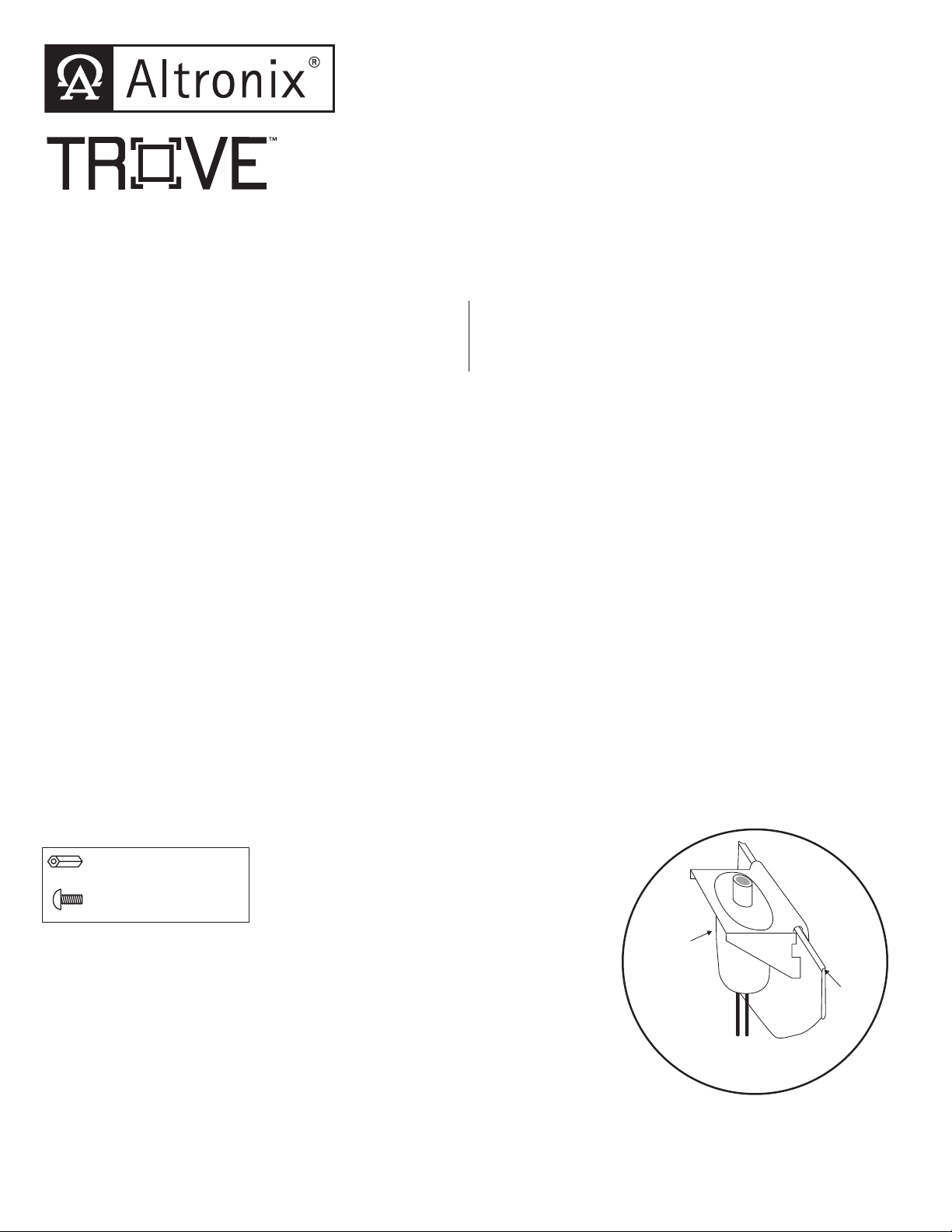
Edge of
Enclosure
to Access Control Panel
or U.L. Listed
Reporting Device
Enclosure
Honeywell
model # 112
Tamper Switch
or equivalent
(provided)
Access & Power Integration
Trove2PX2 TPX2
- Trove2 enclosure with - Altronix/Paxton backplane only
Altronix/Paxton backplane (TPX2)
Installation Guide
TPX2_Rev. 041018
Overview:
Trove2PX2 accommodates Paxton Net2 Plus boards with or without Altronix power supplies and accessories for
access control systems.
Installation Instructions for Trove2:
1. Remove backplane from enclosure prior to mounting (do not discard hardware).
2. Mark and predrill holes in the wall to line up with the top keyholes in the enclosure. Install the upper fasteners and
screws in the wall with the screw heads protruding. Place the enclosure’s upper keyholes over the screws, level and
secure. Mark the position of the lower holes. Remove the enclosure. Drill the lower holes and install the fasteners.
Place the enclosure’s upper keyholes over the upper screws. Install the lower screws and make sure to tighten all screws
(Enclosure Dimensions, pg. 4).
3. Mount included UL Listed tamper switch (Honeywell Model 112 or equivalent) in desired location, opposite hinge.
Slide the tamper switch bracket onto the edge of the enclosure approximately 2” from the right side (Fig. 1, pg. 1).
Connect tamper switch wiring to the Access Control Panel input or the appropriate UL Listed reporting device.
To activate alarm signal open the door of the enclosure.
4. Mount Altronix/Paxton boards to backplane, refer to page 2.
Hardware:
Fig. 1
Nylon or Metal Standoff
5/16” Pan Head Screw
All registered trademarks are property of their respective owners.
Page 2

TPX2: Configuration of Altronix Power Supply
and/or Sub-Assembly Boards and Paxton Net2 Plus Modules
1. Fasten standoffs (provided) to pems that match the hole pattern for Altronix Power Supply/Chargers or Altronix
Sub-Assembly boards (Fig. 2, pg. 2). Fasten metal standoffs in the correct locations to provide proper grounding,
see below (Fig. 2, pg. 2).
Note: Each Altronix sub-assembly position can accommodate one (1) ACM8/ACM8CB, PD4UL/PD4ULCB,
PD8UL/PD8ULCB, MOM5, PDS8(CB) or VR6.
2. Mount boards to standoffs utilizing 5/16” pan head screws (provided) (Fig. 2, 2a, pg. 2).
3. Mount Paxton Net2 Plus modules into the correct positions (Fig. 2, pg. 2).
Note: Paxton Net2 Plus modules have one (1) RJ45 jack and one (1) switch each.
Please make sure that they are mounted correctly, as shown in Fig. 2 below
4. Fasten TPX2 backplane to Trove2 enclosure utilizing pan head screws (provided).
Fig. 2 - Trove2PX2/TPX2 Configurations
Metal
Standoff
Placement
Metal
Standoff
Placement
Altronix
Power
Supply
Altronix
Power
Supply
or
Sub-Assembly
Altronix
Sub-Assembly
Switch
RJ45 Jack
Switch
RJ45 Jack
Switch
RJ45 Jack
Switch
RJ45 Jack
Switch
RJ45 Jack
Switch
RJ45 Jack
Switch
RJ45 Jack
Switch
RJ45 Jack
Switch
RJ45 Jack
Switch
RJ45 Jack
Switch
RJ45 Jack
Switch
RJ45 Jack
Switch
RJ45 Jack
Switch
RJ45 Jack
Switch
RJ45 Jack
Switch
RJ45 Jack
Switch
RJ45 Jack
Switch
RJ45 Jack
Switch
RJ45 Jack
Switch
RJ45 Jack
Fig. 2a
Pem
Standoff
Power Supply or
Pan Head
Sub-Assembly
Screw
- 2 - Trove2PX2
Backplane
Page 3

24.95” (633.7mm)
TPX2 Dimensions
25.375” x 19.375” x 0.325” (644.5mm x 482.6mm x 8.3mm)
19.375”
(482.6mm)
7.5”
(190.5mm)
7.5”
(190.5mm)
16.245” (412.6mm)
12.62” (320.6mm)
8.5” (215.8mm)
0.156”
( 3.96mm)
25.375”
(644.5mm)
12.62”
(320.6mm)
1.0”
(25.4mm)
0.45”
(11.4mm)
7.5”
(190.5mm)
Trove2PX2 - 3 -
1.0”
(25.4mm)
7.5”
(190.5mm)
9.2”
(233.7mm)
Page 4

1.25”
(
)
(
)
(
)
(
)
(
)
(31.75mm)
Trove2PX2 Enclosure Dimensions (H x W x D):
27.25” x 21.75” x 6.5” (692.2mm x 552.5mm x 165.1mm)
21.50”
(546.1mm)
2.00”
(50.8mm)
5.25”
(133.35mm)
3.50”
(88.9mm)
0.5625”
(14.29mm)
3.50”
(88.9mm)
(44.96mm)
2.415”
(61.34mm)
1.77”
5.25”
(133.35mm)
0.685”
(17.399mm)
Knockouts
1.125” (28.32mm)
0.885” (22.479mm)
6.25”
(158.75mm)
6.25”
(158.75mm)
1.25”
(31.75mm)
G
0.85”
(21.59mm)
1.5”
(38.1mm)
27.00”
(685.8mm)
19.80”
(502.92mm)
2.00”
(50.8mm)
6.75”
(171.45mm)
8.25”
(209.54mm)
8.00”
(203.2mm)
0.85”
(21.59mm)
2.00”
(50.8mm)
1.00”
(25.4mm)
1.25”
(31.75mm)
2.00”
50.8mm
Altronix is not responsible for any typographical errors.
140 58th Street, Brooklyn, New York 11220 USA | phone: 718-567-8181 | fax: 718-567-9056
web site: www.altronix.com | e-mail: info@altronix.com | Made in U.S.A.
IITrove2PX2 I10R
- 4 - Trove2PX2
5.25”
133.35mm
7.00”
177.79mm
5.25”
133.35mm
2.00”
50.8mm
1.25”
(31.75mm)
MEMBER
 Loading...