

Page 1

Versatile Access Power
and Integration Enclosures
Installation Guide
Models Include:
Trove2M2
- Trove2 enclosure with Altronix/Mercury backplane
TM2
- Altronix/Mercury backplane only
Trove2V2
- Trove2 enclosure with Altronix/Vertx backplane
TV2
- Altronix/Vertx backplane only
TMV2
- Mercury or Vertx optional door backplane
Rev. 072815 More than just power.™
Page 2
Overview:
Edge of
Enclosure
to Access Control Panel
or U.L. Listed
Reporting Device
Enclosure
Honeywell
model # 112
Tamper Switch
or equivalent
(provided)
Male/Female Standoff
Standoff (Metal or Nylon)
Trove2M2 or Trove2V2 accommodates various combinations of Mercury or Vertx boards with or without Altronix power
supplies and accessories for access systems.
Specifications:
• 19 Gauge grey enclosure with ample knockouts for convenient access.
Enclosure Dimensions (H x W x D): 27.25” x 21.75” x 6.5” (692.15mm x 552.45mm x 165.1mm)
Trove2M2
- Trove2 enclosure with TM2
Altronix/Mercury backplane.
• Includes: tamper switch, cam lock,
lock nuts and mounting hardware.
Trove2M2 accommodates a
combination of the following:
• Two (2) eFlow3NB, eFlow4NB,
eFlow6NB, eFlow102NB or
eFlow104NB.
• Four (4) ACM4(CB), ACM8(CB),
MOM5, PD4UL(CB), PD8UL(CB).
• Six (6) EP1502, MR52, MR16IN,
MR16OUT.
• Six (6) EP2500 or MUX8.
• Five (5) MR51e.
Trove2V2
- Trove2 enclosure with TV2
Altronix/Vertx backplane.
• Includes: tamper switch, cam lock,
lock nuts and mounting hardware.
Trove2V2 accommodates a
combination of the following:
• Two (2) eFlow3NB, eFlow4NB,
eFlow6NB, eFlow102NB or
eFlow104NB.
• Four (4) ACM4(CB), ACM8(CB),
MOM5, PD4UL(CB), PD8UL(CB).
• Six (6) V100, V200, V300,
V1000 or V2000.
Backplanes Only:
TM2
- Altronix/Mercury backplane only.
• Includes: lock nuts and
mounting hardware.
TV2
- Altronix/Vertx backplane only.
• Includes: lock nuts and
mounting hardware.
Optional Door Backplane:
TMV2
- Mercury or Vertx door
backplane only.
• Includes: lock nuts and
mounting hardware.
• Two (2) MR50.
Trove2M2, Trove2V2 Installation Instructions:
Wiring methods shall be in accordance with the National Electrical Code/NFPA 70/ANSI, and with all local codes and
authorities having jurisdiction. Product is intended for indoor use only.
1. Remove backplane from enclosure. Do not discard hardware.
2. Mount unit in the desired location. Mark and predrill holes in the wall to line up with the top three keyholes in the
enclosure. Install three upper fasteners and screws in the wall with the screw heads protruding. Place the enclosure’s
upper keyholes over the three upper screws, level and secure. Mark the position of the lower three holes. Remove the
enclosure. Drill the lower holes and install the three fasteners. Place the enclosure’s upper keyholes over the three
upper screws. Install the three lower screws and make sure to tighten all screws (Enclosure Dimensions, pg. 10).
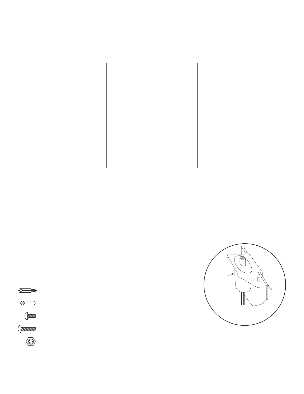
3. Mount UL Listed tamper switch (included) (Ademco model 112 or equivalent) at the top of the enclosure.
Slide the tamper switch bracket onto the edge of the enclosure approximately 2” from the right side (Fig. 1, pg. 2).
Connect tamper switch wiring to the Access Control Panel input or the
appropriate UL Listed reporting device.
To activate alarm signal open the door of the enclosure.
4. Mount Altronix/Mercury/Vertx boards to backplane, refer to pages 3-12.
Fig. 1
Hardware:
5/16” Pan Head Screw
7/8” Pan Head Screw
- 2 - Altronix/Mercury/Vertx Enclosure
Lock Nut
Page 3
Mercury
EP1502, MR52,
MR16IN, MR16OUT
Mercury
EP1502, MR52,
MR16IN, MR16OUT
Mercury
EP1502, MR52,
MR16IN, MR16OUT
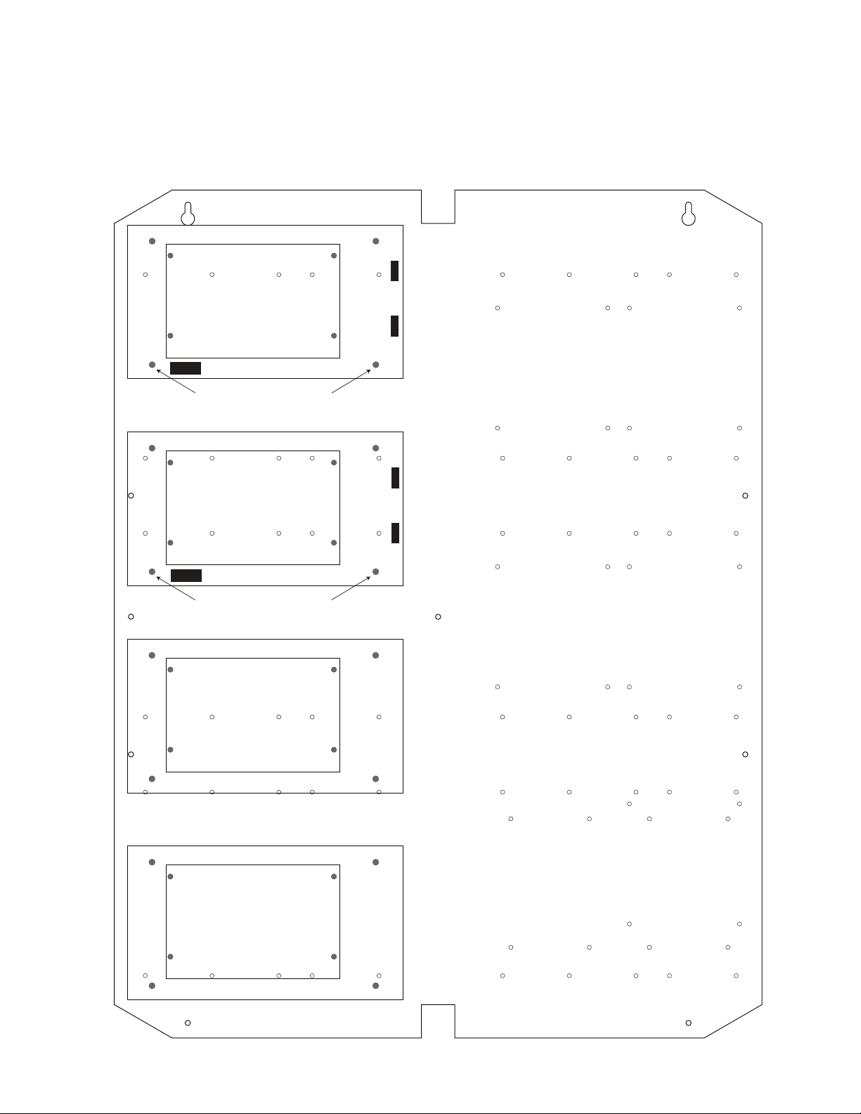
TM2: Configuration of Altronix Power Supply and/or Sub-Assembly Boards
1. Fasten standoffs (provided) to pems that match the hole pattern for Altronix Power Supply/Chargers or Altronix
Sub-Assembly boards (Fig. 2, pg. 3). Use male/female nylon standoffs for the upper two mounting holes in the
board. Use metal standoffs for the bottom mounting holes to provide sufficient grounding for the board.
2. Affix boards to standoffs (Fig. 2, pg. 3) by pressing down the upper mounting holes onto nylon standoffs.
Use provided mounting screws to affix the lower mounting holes. Make sure that boards are locked onto standoffs.
3. Fasten backplane to Trove2 enclosure utilizing lock nuts (provided).
Fig. 2
Altronix
Power Supply or
Sub-Assembly
Metal Standoff Placement
Altronix
Power Supply or
Sub-Assembly
Metal Standoff Placement
Altronix
Sub-Assembly
Altronix
Sub-Assembly
Altronix/Mercury/Vertx Enclosure - 3 -
Page 4
Mercury
EP2500,
MUX8
Mercury
EP2500,
MUX8
Mercury
EP2500,
MUX8
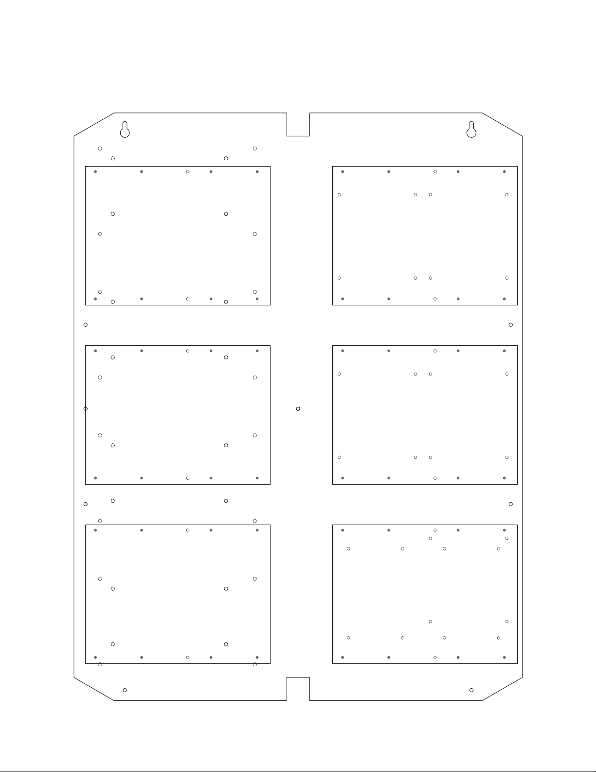
TM2: Configuration of Mercury Boards
1. Fasten standoffs (provided) to pems that match the hole pattern for Mercury EP1502, MR52, MR16IN or MR16OUT
(Fig. 3, pg. 4). Use male/female nylon standoffs only.
2. Affix boards to standoffs (Fig. 3, pg. 4) by pressing down the mounting holes onto nylon standoffs.
Make sure that boards are locked onto standoffs.
3. Fasten backplane to Trove2 enclosure utilizing lock nuts (provided).
Fig. 3
Mercury
EP1502, MR52,
MR16IN, MR16OUT
Mercury
EP1502, MR52,
MR16IN, MR16OUT
Mercury
EP1502, MR52,
MR16IN, MR16OUT
Mercury
EP1502, MR52,
MR16IN, MR16OUT
Mercury
EP1502, MR52,
MR16IN, MR16OUT
MR16IN, MR16OUT
Mercury
EP1502, MR52,
- 4 - Altronix/Mercury/Vertx Enclosure
Page 5
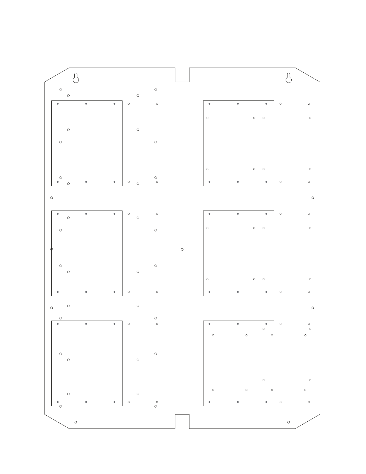
TM2: Configuration of Mercury Boards (cont’d)
1. Fasten standoffs (provided) to pems that match the hole pattern for Mercury EP2500 or MUX8 (Fig. 4, pg. 5).
Use male/female nylon standoffs only.
2. Affix boards to standoffs (Fig. 4, pg. 5) by pressing down the mounting holes onto nylon standoffs.
Make sure that boards are locked onto standoffs.
3. Fasten backplane to Trove2 enclosure utilizing lock nuts (provided).
Fig. 4
Mercury
EP2500,
MUX8
Mercury
EP2500,
MUX8
Mercury
EP2500,
MUX8
Mercury
EP2500,
MUX8
Mercury
EP2500,
MUX8
Altronix/Mercury/Vertx Enclosure - 5 -
Mercury
EP2500,
MUX8
Page 6

TM2: Configuration of Mercury Boards (cont’d)
1. Fasten standoffs (provided) to pems that match the hole pattern for Mercury EP1501 or MR51e (Fig. 5, pg. 6).
Use male/female nylon standoffs only.
2. Affix boards to standoffs (Fig. 5, pg. 6) by pressing down the mounting holes onto nylon standoffs.
Make sure that boards are locked onto standoffs.
3. Fasten backplane to Trove2 enclosure utilizing lock nuts (provided).
Fig. 5
Mercury
EP1501,
MR51e
Mercury
EP1501,
MR51e
Mercury
EP1501,
MR51e
Mercury
EP1501,
MR51e
Mercury
EP1501,
MR51e
- 6 - Altronix/Mercury/Vertx Enclosure
Page 7

TM2: Configuration of Mercury Boards (cont’d)
1. Fasten standoffs (provided) to pems that match the hole pattern for Mercury MR50 (Fig. 6, pg. 7).
Use male/female nylon standoffs only.
2. Affix boards to standoffs (Fig. 6, pg. 7) by pressing down the mounting holes onto nylon standoffs.
Make sure that boards are locked onto standoffs.
3. Fasten backplane to Trove2 enclosure utilizing lock nuts (provided).
Fig. 6
Mercury
MR50
Altronix/Mercury/Vertx Enclosure - 7 -
Mercury
MR50
Page 8

Altronix
Power Supply or
Sub-Assembly
Metal Standoff Placement
Metal Standoff Placement
Altronix
Power Supply or
Sub-Assembly
Altronix
Sub-Assembly
Altronix
Sub-Assembly
Altronix
Sub-Assembly
Altronix
Sub-Assembly
Altronix
Sub-Assembly
Altronix
Sub-Assembly
TV2: Configuration of Altronix Power Supply and/or Sub-Assembly Boards
1. Fasten standoffs (provided) to pems that match the hole pattern for Altronix Power Supply/Chargers or Altronix
Sub-Assembly boards (Fig. 7, pg. 8). Use male/female nylon standoffs for the upper two mounting holes in the
board. Use metal standoffs for the bottom mounting holes to provide sufficient grounding for the board.
2. Affix boards to standoffs (Fig. 7, pg. 8) by pressing down the upper mounting holes onto nylon standoffs.
Use provided mounting screws to affix the lower mounting holes. Make sure that boards are locked onto standoffs.
3. Fasten backplane to Trove2 enclosure utilizing lock nuts (provided).
Fig. 7
- 8 - Altronix/Mercury/Vertx Enclosure
Page 9

TV2: Configuration of Vertx Boards
Vertx
V100, V200, V300,
V1000, V2000
Vertx
V100, V200, V300,
V1000, V2000
Vertx
V100, V200, V300,
V1000, V2000
Vertx
V100, V200, V300,
V1000, V2000
Vertx
V100, V200, V300,
V1000, V2000
Vertx
V100, V200, V300,
V1000, V2000
1. Fasten standoffs (provided) to pems that match the hole pattern for Vertx V100, V200, V300, V1000 or V2000
boards (Fig. 8, pg. 9).
2. Mount boards to standoffs (Fig. 8, pg. 9) utilizing 7/8” pan head screws (provided).
3. Fasten backplane to Trove2 enclosure utilizing lock nuts (provided).
Fig. 8
Altronix/Mercury/Vertx Enclosure - 9 -
Page 10

TMV2: Configuration of Mercury Boards
Mercury
EP1502, MR52,
MR16IN, MR16OUT
Mercury
EP1502, MR52,
MR16IN, MR16OUT
Mercury
EP1502, MR52,
MR16IN, MR16OUT
Mercury
EP1502, MR52,
MR16IN, MR16OUT
Mercury
EP1502, MR52,
MR16IN, MR16OUT
Mercury
EP1502, MR52,
MR16IN, MR16OUT
Mercury
EP2500,
MUX8
Mercury
EP2500,
MUX8
Mercury
EP2500,
MUX8
1. Fasten standoffs (provided) to pems that match the hole pattern for Mercury EP1502, MR52, MR16IN or MR16OUT
(Fig. 9, pg. 10). Use male/female nylon standoffs only.
2. Affix boards to standoffs (Fig. 9, pg. 10) by pressing down the mounting holes onto nylon standoffs.
Make sure that boards are locked onto standoffs.
3. Fasten backplane to Trove2 enclosure door utilizing lock nuts (provided).
Fig. 9
- 10 - Altronix/Mercury/Vertx Enclosure
Page 11

TMV2: Configuration of Mercury Boards (cont’d)
Mercury
EP2500,
MUX8
Mercury
EP2500,
MUX8
Mercury
EP2500,
MUX8
Mercury
EP2500,
MUX8
Mercury
EP2500,
MUX8
Mercury
EP2500,
MUX8
1. Fasten standoffs (provided) to pems that match the hole pattern for Mercury EP2500 or MUX8 (Fig. 10, pg. 11).
Use male/female nylon standoffs only.
2. Affix boards to standoffs (Fig. 10, pg. 11) by pressing down the mounting holes onto nylon standoffs.
Make sure that boards are locked onto standoffs.
3. Fasten backplane to Trove2 enclosure door utilizing lock nuts (provided).
Fig. 10
Altronix/Mercury/Vertx Enclosure - 11 -
Page 12

TMV2: Configuration of Vertx Boards
Vertx
V100, V200, V300,
V1000, V2000
Vertx
V100, V200, V300,
V1000, V2000
Vertx
V100, V200, V300,
V1000, V2000
Vertx
V100, V200, V300,
V1000, V2000
Vertx
V100, V200, V300,
V1000, V2000
Vertx
V100, V200, V300,
V1000, V2000
1. Fasten standoffs (provided) to pems that match the hole pattern for Vertx V100, V200, V300, V1000 or V2000
boards (Fig. 11, pg. 12).
2. Mount boards to standoffs (Fig. 11, pg. 12) utilizing 7/8” pan head screws (provided).
3. Fasten backplane to Trove2 enclosure door utilizing lock nuts (provided).
Fig. 11
- 12 - Altronix/Mercury/Vertx Enclosure
Page 13

24.95” (633.73mm)
TM2 and TV2 Mounting Diagram
19.4”
(492.76mm)
7.5”
(190.5mm)
7.5”
(190.5mm)
0.156”
( 3.96mm)
16.245” (412.62mm)
12.62” (320.55mm)
8.495” (215.77mm)
25.4”
(645.16mm)
12.62”
(320.55mm)
1.0”
(25.4mm)
0.45”
(11.43mm)
7.5”
(190.5mm)
1.0”
(25.4mm)
7.5”
(190.5mm)
9.2”
(233.68mm)
- 13 - Altronix/Mercury/Vertx Enclosure
Page 14

23.7”
(602mm)
TMV2 Mounting Diagram
18.1”
(459.7mm)
13.7”
(350mm)
7.4”
(188mm)
0.156”
( 3.96mm)
0.45”
(11.43mm)
2.075”
(52.7mm)
10.82”
(274.8mm)
8.7”
(221mm)
8”
(203.2mm)
8.7”
(221mm)
11.8”
(299.7mm)
7.5”
(190.5mm)
7.85”
(199.39mm)
13.7”
(350mm)
- 14 - Altronix/Mercury/Vertx Enclosure
Page 15

Notes:
- 15 - Altronix/Mercury/Vertx Enclosure
Page 16

1.25”
(
)
(
)
(
)
(
)
(
)
(31.75mm)
Enclosure Dimensions (H x W x D approximate):
27.25” x 21.75” x 6.5” (692.15mm x 552.45mm x 165.1mm)
21.50”
(546.1mm)
2.00”
(50.8mm)
5.25”
(133.35mm)
3.50”
(88.9mm)
0.5625”
(14.29mm)
3.50”
(88.9mm)
(44.96mm)
2.415”
(61.34mm)
1.77”
5.25”
(133.35mm)
0.685”
(17.399mm)
Knockouts
1.125” (28.32mm)
0.885” (22.479mm)
6.25”
(158.75mm)
6.25”
(158.75mm)
1.25”
(31.75mm)
G
0.85”
(21.59mm)
1.5”
(38.1mm)
27.00”
(685.8mm)
19.80”
(502.92mm)
2.00”
(50.8mm)
6.75”
(171.45mm)
8.25”
(209.54mm)
0.85”
(21.59mm)
1.00”
(25.4mm)
1.25”
(31.75mm)
2.00”
50.8mm
Altronix is not responsible for any typographical errors. Product specifications are subject to change without notice.
140 58th Street, Brooklyn New York 11220 USA, 718-567-8181, fax: 718-567-9056
website: www.altronix.com, e-mail: info@altronix.com. Made in USA.
IITrove2M2/Trove2V2 - Rev. 100515 F21P
- 16 - Altronix/Mercury/Vertx Enclosure
5.25”
133.35mm
7.00”
177.79mm
5.25”
133.35mm
2.00”
50.8mm
1.25”
(31.75mm)
8.00”
(203.2mm)
2.00”
(50.8mm)
MEMBER
 Loading...