

Page 1
AL125ULB
Access Control Power Supply/Chargers
Overview:
The AL125ULB is a power limited power supply/charger that converts a low voltage AC input into two individually
PTC protected 12VDC or 24VDC outputs (see specifications). They are intended for use in applications requiring
UL Listing for Access Control (UL 294) and applications requiring an interface with Fire Alarm Control Panels.
Specifications:
Agency Listings:
• UL recognized component.
•
NFPA 101 (Life Safety)
Input Rating:
• 24VAC/40VA.
Output Rating:
• 12VDC or 24VDC selectable, Class 2 Rated
po
wer limited outputs.
• 1 amp total supply current @ 12VDC or 24VDC.
• Filtered and electronically regulated output.*
Battery Backup:
• Built-in charger for sealed lead acid or
gel type batteries.
•
Maximum charge current: 400mA.
• Automatic switch over to stand-by battery when
AC fails.
Special Features:
• AC power and unit status indicator on the
front panel.
• “NO” trigger input.
•
Supervised Fire Alarm Disconnect (Latching w/reset or
Non-Latching).
Board Dimensions (approximate):
3.1”W x 3.9”L x 1.4”H
*Note: When unit is powered by battery back up (AC Fail condition) the voltage range is 9.3V-13.2V and
19.55V-26.4V for 12 and 24 volt operation respectively.
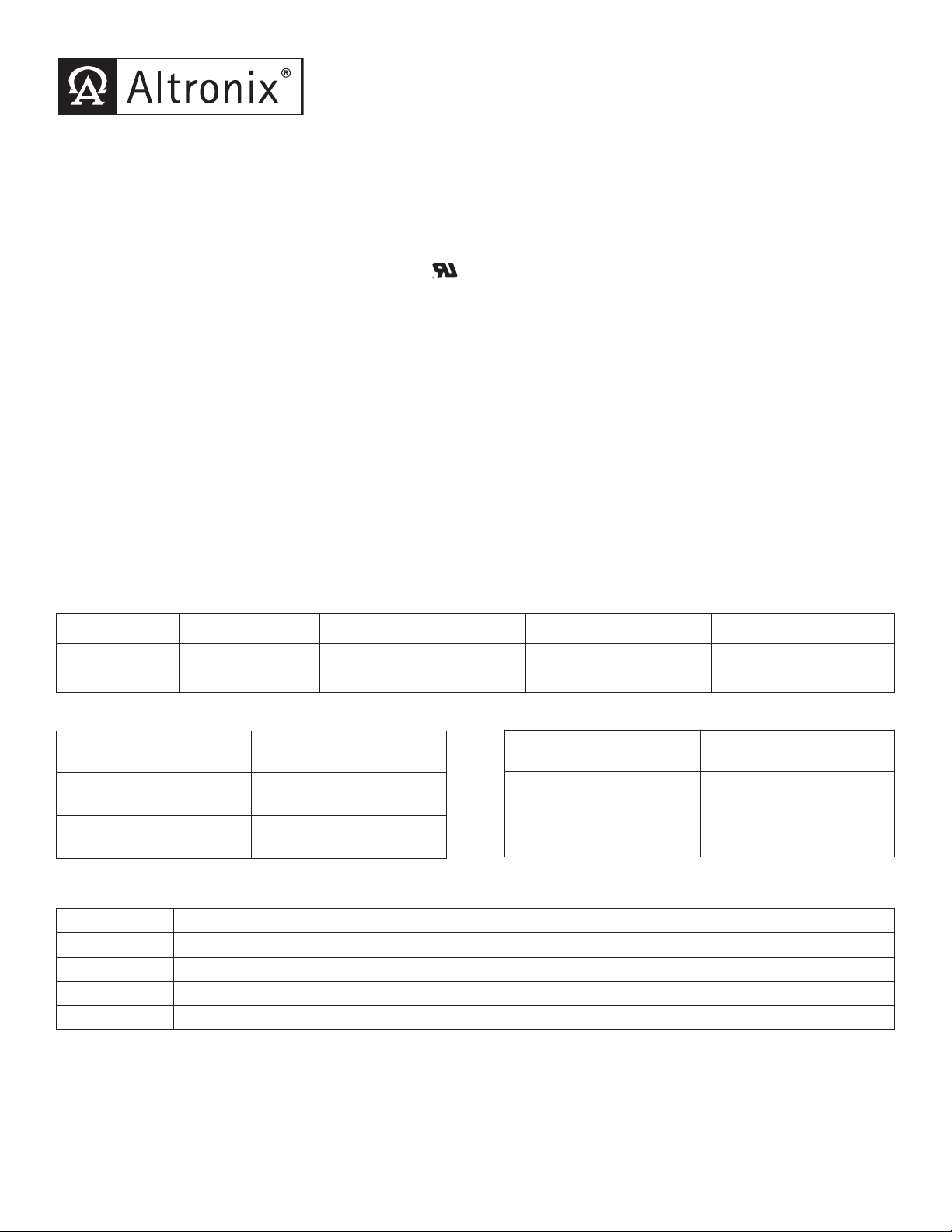
Power Supply Output Specifications:
Output VDC Switch Position Max. Stand-by Load DC Max.Alarm Load DC Battery (optional)
12VDC SW2 Open 1 amp 1 amp 12VDC
24VDC SW2 Closed 1 amp 1 amp 24VDC
Stand-by Specifications:
Output
12VDC/4AH Battery
24VDC/4AH Battery
4 hr. of Stand-by &
5 min. of Alarm
Stand-by = .5 amp
Alarm = 1 amp
Stand-by = .5 amp
Alarm = 1 amp
Output
12VDC/7AH Battery
24VDC/7AH Battery
4 hr. of Stand-by &
5 min. of Alarm
Stand-by = 1 amp
Alarm = 1 amp
Stand-by = 1 amp
Alarm = 1 amp
LED Diagnostics:
Green (AC) Power Supply Status
ON Normal operating condition.
OFF No DC output.
Slow Blink Loss of AC.
Rapid Blink Unit is triggered, awaiting reset. Fire alarm interface activated.
Page 2
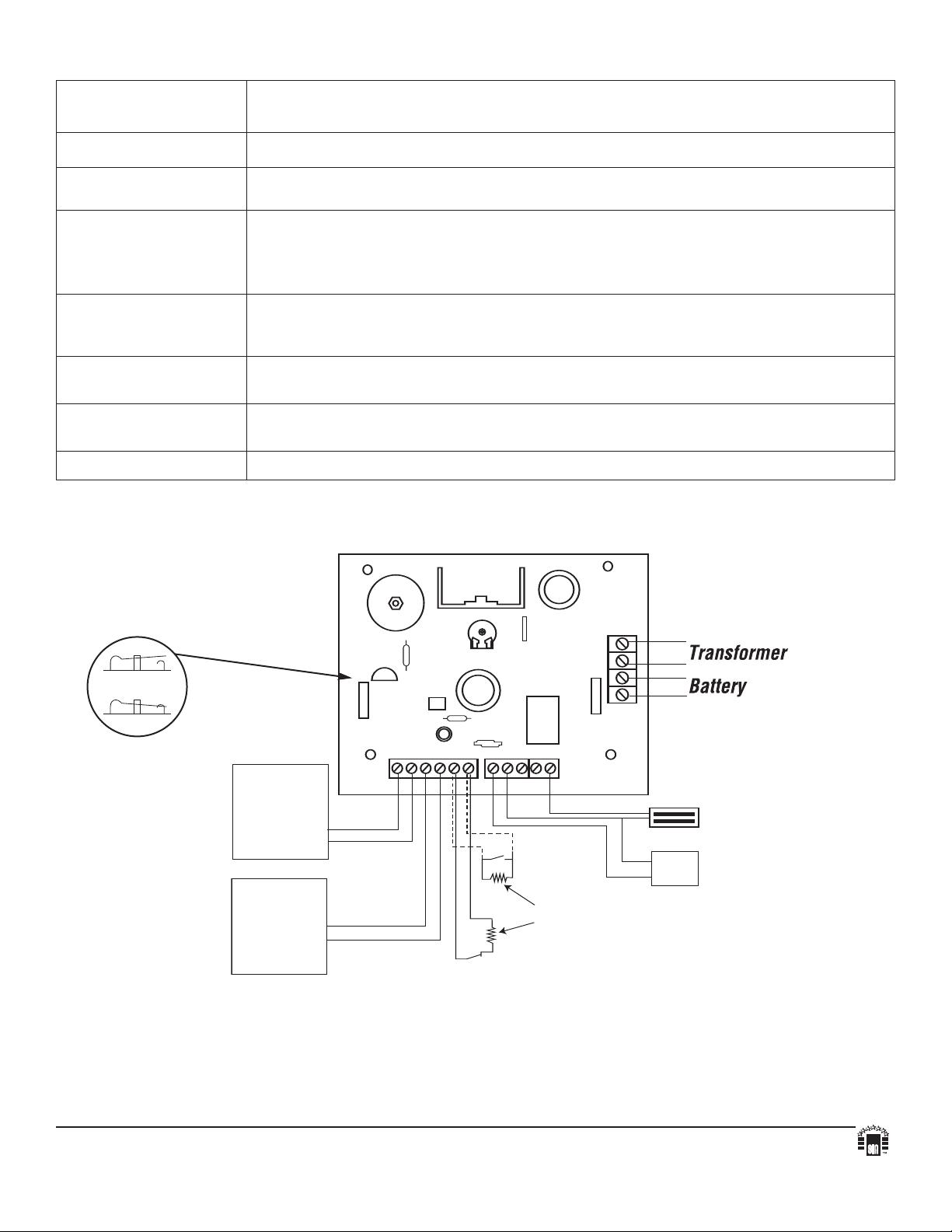
Terminal Identification:
V
R1
NO NOGND GND
FACP1 FACP2
S
TRIKE+
COM-- LOCK+
+ AUX --
TRIG
INPUT
RESET
SW1
+ BAT --
XFMR
SW2:
12VDC - Open
24VDC - Closed
Normal Open
Access Control
Triggering
Device
Normal Open
Reset Device
2.2K EOL
(supplied)
MAG LOCK
NC
FACP
NO
FACP
{ }
Card
Reader
O
PEN SWITCH
CLOSED SWITCH
Terminal
Legend
Function/Description
XFMR Low voltage transformer connections.
+AUX --
LOCK+
STRIKE+
COM --
FACP1
FACP2
TRG INPUT
NO, GND
RESET
NO, GND
Aux power output terminals. These terminals will supply 12VDC or 24VDC,
not affected by trigger, reset or fire alarm interface.
Switched power output. Fail-Safe [LOCK+] supplies positive power when unit is not
triggered and FACP interface is inactive. Fail-Secure [STRIKE+] supplies positive power
when unit is triggered and/or fire alarm interface is activated. [COM-- ] supplies
negative power.
Supervised by 2.2K end of line resistor FACP interface. Short or open will cause power to
be dropped to terminal marked [LOCK+] and supply power to terminal marked [STRIKE+].
Condition can be maintained even after restoration of the circuit (latching mode).
Short between these two terminals will cause power to be dropped to terminal marked
[LOCK+] and supplied to terminal marked [STRIKE+].
Momentary short between these terminals would end latching FACP interface condition
Feature active only if latching FACP is selected (SW1 closed).
+ BAT -- Stand-by battery connections.
Application Diagram:
Fig. 1
Fig. 1A - SW1
Altronix is not responsible for any typographical errors.
140 58th Street, Brooklyn, New York 11220 USA, 718-567-8181, fax: 718-567-9056
website: www.altronix.com, e-mail: info@altronix.com, Lifetime Warranty, Made in U.S.A.
IIAL125ULB - Rev. 012003 B03I
MEMBER
 Loading...