

Page 1

AL1012ULX Series
Power Supply/Charger
Installation Guide
Models Include:
• AL1012ULX
- Single Output
• AL1012ULXPD4 • AL1012ULXPD4CB
- Four (4) Fused Outputs - Four (4) PTC Outputs
• AL1012ULXPD8 • AL1012ULXPD8CB
Eight (8) Fused Outputs - Eight (8) PTC Outputs
-
• AL1012ULXPD16 • AL1012ULXPD16CB
- Sixteen (16) Fused Outputs - Sixteen (16) PTC Outputs
Rev. 090302
Page 2
Overview:
The AL1012ULX is a power supply that converts a 115VAC / 60Hz input, to a 12VDC output (see specifications).
The AL1012ULX is a base unit for a series of UL Listed multi-output power supply/chargers, including:
AL1012ULXPD4, AL1012ULXPD4CB, AL1012ULXPD8, AL1012ULXPD8CB, AL1012ULXPD16,
AL1012ULXPD16CB (Refer to AL1012ULX Series Power Supply Configuration Reference Chart).
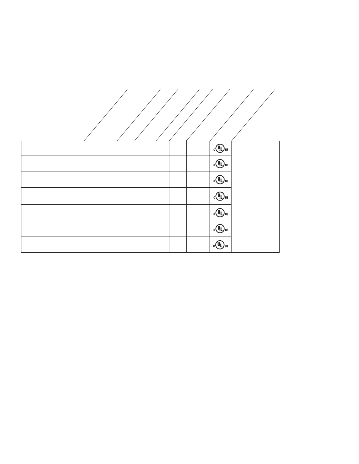
AL1012ULX Series Power Supply Configuration Reference Chart:
Class 2 Rated
Model Number
Altronix
Distribution
Accessory Power
Module(s)
Number of Outputs
AL1012ULX - 1 - - - 10
Power Limited Outputs
Fused Outputs
PTC Outputs
per Output
Output Rating (amp)
Agency Lisitings
UL Listings and
File Numbers
AL1012ULXPD4 PD4UL 4 - x - 3.5
AL1012ULXPD4CB PD4ULCB
4 x - x 2.5
AL1012ULXPD8 PD8UL 8 - x - 3.5
AL1012ULXPD8CB PD8ULCB 8 x - x 2.5
AL1012ULXPD16 PD8UL 16 - x - 3.5
AL1012ULXPD16CB PD8ULCB 16 x - x 2.5
Specifications:
Input:
• Input 115VAC / 60Hz, 1.9 amp.
• AC input and DC output LED indicators.
Output:
• 12VDC output.
• 10 amp total supply current at 12VDC.
•
F
iltered and electronically regulated outputs.
Short circuit and thermal overload protection.
•
Battery Backup:
• Maximum charge current .7 amp.
• Built-in charger for sealed lead acid or
gel type batteries.
Battery Backup (cont’d):
• Automatic switch over to stand-by battery when
AC fails.
• Zero voltage drop when switched over to
battery backup.
Supervision:
•
A
Battery presence and low battery supervision
•
(for
Added Features:
• Power supply, enclosure, cam lock and battery leads.
UL 294
(File # BP6714)
UL Listed for
Access Control
Systems.
“Signal Equipment”
Evaluated to
CSA Standard
C22.2
No.205-M1983
C fail supervision (form "C" contacts).
m “C” contacts).
- 2 - AL1012ULXseries
Page 3

Installation Instructions:
Wiring methods shall be in accordance with the National Electrical Code/NFPA 70/NFPA 72/ANSI, and with all local
codes and authorities having jurisdiction. Product is intended for indoor use only.
1. Mount unit in desired location. Mark and predrill holes in the wall to line up with the top two keyholes in the
enclosure. Install two upper fasteners and screws in the wall with the screw heads protruding. Place the enclosure’s
upper keyholes over the two upper screws, level and secure. Mark the position of the lower two holes. Remove the
enclosure. Drill the lower holes and install the three fasteners. Place the enclosure’s upper keyholes over the two
upper screws. Install the two lower screws and make sure to tighten all screws
Secure enclosure to earth ground.
2. Connect AC power (115VAC / 60 Hz to terminals marked [L, G, N]
(Fig. 1, pg. 5). Use 14 AWG or larger for all
power connections (Battery, DC output, AC input). Use 22 AWG to 18 AWG for power limited circuits (AC Fail/
Low Battery reporting). Keep power limited wiring separate from non-power limited wiring (115VAC / 60Hz Input,
Battery Wires). Minimum .25” spacing must be provided.
3. Measure output voltage before connecting device. This helps avoid potential damage.
4. Connect devices to be powered:
a. For Power Supply Board connect to terminals marked [+ DC -]
. For Power Distribution Module(s) connect devices to be powered to terminal pairs 1 to 4 marked
b
[1P & 1N thru 4P & 4N]
(Fig. 2, pg. 6) or 1 to 8 marked [1P & 1N thru 8P & 8N] (Fig. 3, pg. 6) carefully
(Fig. 1, pg. 5).
observing correct polarity.
When servicing the unit, AC mains should be removed.
5. For Access Control applications, batteries are optional. When batteries are not used a loss of AC will result in the
loss of output voltage.
When the use of stand-b
y batteries is desired, they must be lead acid or gel type.
6. Connect appropriate signaling notification devices to terminals marked [AC FAIL & BAT FAIL]
supervisory relay outputs.
glar alarm or access control applications, “AC Fail” relay must be used to
Note: When used in f
ire alarm, b
ur
provide a visual indication of AC power on.
(Enclosure Dimensions, pg. 8).
(Fig. 1, pg. 5)
Wiring:
USE 14
Note: Take care to keep power limited circuits separate from non-power limited wiring (115VAC, Battery).
AWG or larger for all power connections.
Maintenance:
Unit should be tested at least once a y
Output Voltage Test: Under normal load conditions, the DC output voltage should be checked for proper voltage level.
Battery
batter
Test:
Under nor
y terminal and at the board terminals marked [- BAT +] to insure there is no break in the battery connection wires.
mal load conditions check that the battery is fully charged, check specified voltage both at
Note: Maximum charging current under discharges is .7 amp.
Note: Expected battery life is 5 years, however it is recommended changing batteries in 4 years or less if needed.
ear for the proper operation as follows:
AL1012ULXseries - 3 -
Page 4

LED Diagnostics:
AL1012ULXB - Power Supply Board
Red (DC) Green (AC) Power Supply Status
ON ON Normal operating condition
ON OFF Loss of AC, Stand-by battery supplying power
OFF ON No DC output
OFF OFF Loss of AC. Discharged or no stand-by battery. No DC output.
PD4/PD4CB/PD8/PD8CB - Power Distribution Module
Green Power Distribution Module Status
ON Normal operating condition.
Terminal Identification:
AL1012ULXB - Power Supply Board
Terminal Legend Function/Description
L, G, N Connect 115VAC to these terminals: L to Hot, N to Neutral, G to ground.
- DC + 12VDC @ 10 amp continuous non-power limited output.
AC FAIL Indicates loss of AC power, e.g. connect to annuciator/alarm panel. Relay normally energized
NC, C, NO when AC power is present. Contact rating 1 amp @ 30VDC. AC Fail condition will report
approximately one (1) to one minute after loss of AC. To delay report for 6 hours cut jumper
J1 on the Power Supply Board (AC trouble output delay option). If this mode is selected the Power
Supply Board must be reset by removing all power to it for 30 seconds.
BAT FAIL Indicates low battery condition, e.g. connect to alarm panel. Relay normally energized
NO, C, NC when DC power is present. Contact rating 1 amp @ 30VDC. Low battery conditions will report
ximately 10.5VDC Battery presence detection will report approimately 1 minute after battery
appro
remains undetected (missing or removed).
- BAT + Stand-by battery connections. Maximum charge rate .7 amp.
PD4/PD4CB/PD8/PD8CB - Power Distribution Module
Terminal Legend Function/
PD4/PD4CB PD8/PD8CB Description
1P to 4P 1P to 8P Positive DC power outputs.
1N to 4N 1N to 8N Negative DC power outputs.
- 4 - AL1012ULXseries
Page 5

N
COMMON POWER OUTPUTS
P
FUSED POWER OUTPUTS
D1
INPUT
R1
LED
3.5A 250V 3.5A 250V
3.5A 250V
1
2
DC Output to devices
(non-power limited)
G
reen
L
ead
Battery connection (non-power limited)
Door
Wire Strap
(from
Enclosure
to Door)
115 power
mains
(non-power
limited)
Divider
CAUTION: De-energize unit prior to servicing. For continued protection
against risk of electric shock and fire hazard replace fuse with the same type
and rating 3.5A, 250V. Replace fuse cover before energizing.
Class 1
Provide 1/4" separation between
power limited and all other circuits
Battery and AC
Supervision Circuit
(power limited)
Use separate knockout
Non-power limited
+ DC ---
B
AT FAIL
NC C NO NC C NO
+ BAT ---
DC
A
C FAIL
L
G N
AC
3.5A 250V
Green Lead
Keep power limited wiring separate from non-power limited. Use minimum .25" spacing.
12VDC Rechargeable Battery
(optional)
Fig. 1
AL1012ULXseries - 5 -
Page 6

I
NPUT
L
ED
PD4
POWER DISTRIBUTING UNIT
1P, 2P, 3P, 4P = FUSED OUTPUTS
1N, 2N, 3N, 4N = COMMON OUTPUTS
F1
F1
F2 F3 F4
COMMON POWER OUTPUTS
1P
1
N
2P
2N
3P
3N
4P
4N
DC Output to devices
From Power Supply
Board
(Factory Installed)
Used
on PTC
Models
PD8
N
COMMON POWER OUTPUTS
P
FUSED POWER OUTPUTS
1 2 3 4 5 6 7 8
1
ALTRONIX CORP. MADE IN USA
BROOKLYN, NY 11220
D
1
INPUT
R1
LED
MAIN
FUSE
DC Output to devices
From Power Supply
Board
(Factory Installed)
Used
on PTC
Models
Fig. 2
Power Distribution Module(s):
Fig. 3
- 6 - AL1012ULXseries
Page 7

Notes:
AL1012ULXseries - 7 -
Page 8

Enclosure Dimensions:
1.285
1.285
1
5.5”H x 12”W x 4.5”D
Altronix is not responsib
Altronix Corp.
140 58th Street, Brooklyn, New York 11220 USA, 718-567-8181, fax: 718-567-9056
eb site: www
w
IIAL1012ULX series E24G
- 8 - AL1012ULXseries
le for an
.altronix.com, e-mail: info@altronix.com, Lifetime Warranty, Made in U.S.A.
y typo
raphical errors.
g
MEMBER
 Loading...