

Page 1

ACMS8 Series
Sub-Assembly
Access Power Controllers
Installation Guide
Models Include:
ACMS8
- Eight (8) Fuse Protected Outputs
ACMS8CB
- Eight (8) PTC Protected Outputs
Rev. 090518
More than just power.
TM
Page 2

Altronix ACMS8(CB) Access Power Controller’s dual input design allows power to be steered from two (2)
independent low voltage 12 or 24VDC power sources to eight (8) independently controlled fuse (ACMS8) or
PTC (ACMS8CB) protected outputs. Power outputs of ACMS8(CB) can be converted to dry form “C” contacts.
Outputs are activated by an open collector sink, normally open (NO), normally closed (NC) dry trigger input,
or wet output from an Access Control System, Card Reader, Keypad, Push Button, PIR, etc. ACMS8(CB) will
route power to a variety of access control hardware devices including Mag Locks, Electric Strikes, Magnetic
Door Holders, etc. Outputs will operate in both Fail-Safe and/or Fail-Secure modes. The FACP Interface enables
Emergency Egress, Alarm Monitoring, or may be used to trigger other auxiliary devices. The fire alarm disconnect feature is individually selectable for any or all of the eight (8) outputs. The spade connectors allow you to
daisy chain power to multiple ACMS8(CB) modules. This feature allows you to distribute the power over more
outputs for larger systems.
Specifications:
Overview:
Power Supply Input Options:
• Input 1 and Input 2 voltage range:
ACMS8: 5VDC to 24VDC, up to 10A each,
20A total input.
ACMS8CB: 5VDC to 24VDC up to 10A each,
16A total input.
• Eight (8) trigger inputs:
a) Normally open (NO) inputs.
b) Normally closed (NC) inputs.
c) Open collector sink inputs.
d) Wet Input (5VDC - 24VDC) with 10K resistor
e) Any combination of the above.
Outputs:
• ACMS8: Fuse protected outputs rated @ 2.5A
per output, non power-limited.
Total output 20A max.
Do not exceed the individual
power supply ratings.
ACMS8CB: PTC protected outputs rated @ 2A
per output, Class 2 power-limited.
Total output 16A max.
Do not exceed the individual
power supply ratings.
Total output current should not exceed max. current
rating of the power supplies employed on each input.
See Maximum Output of Altronix Power Supplies.
• Eight (8) selectable independently controlled
outputs or eight (8) indepently controlled
Form “C” relay outputs (see below for ratings):
a) Fail-Safe and/or Fail-Secure power outputs.
b) Form “C” relays rated @ 2.5A.
c) Auxiliary power outputs (unswitched).
d) Any combination of the above.
• Individual outputs may be set to OFF position for
servicing (output jumper set to middle position).
Does not apply to Dry Contact applications.
Outputs (cont’d):
• Any of the eight (8) fuse/PTC protected power
outputs are selectable to follow power Input 1 or
Input 2. Output voltage of each output is the same
as the input voltage of the input selected.
• Surge suppression.
Fire Alarm Disconnect:
• Fire Alarm disconnect (latching or non-latching) is
individually selectable for any or all of the
eight (8) outputs.
Fire Alarm disconnect input options:
a) Normally open [NO] or normally closed [NC]
dry contact input. Polarity reversal input from
FACP signaling circuit.
• FACP output relay [NC] contact or provides
10k resistance with [EOL JMP] intact.
Outputs Ratings:
ACMS8: Fuses are rated 2.5A each.
ACMS8CB: PTCs are rated 2A each.
Fuse Ratings:
• Main input fuses rated @ 10A/32V each.
LED Indicators:
• Red LEDs indicate outputs are triggered.
• Blue LED indicates FACP disconnect is triggered.
• Individual voltage LED indicates 12VDC (Green)
or 24VDC (Red/Green).
Environmental:
• Operating temperature: 0ºC to 49ºC ambient.
• Humidity: 20 to 93%, non-condensing.
Mechanical:
• Board Dimensions (W x L x H approximate):
7.65” x 4.125” x 1.25”
(194.3mm x 104.8mm x 31.8mm).
• Product weight (approx.): 0.7 lb. (0.32 kg).
• Shipping weight (approx.): 0.95 lb. (0.43 kg).
- 2 - ACMS8/CB Sub-Assembly
Page 3

Wiring methods shall be in accordance with the National Electrical Code NFPA 70/NFPA 72/ ANSI / Canadian
1
2
3
4
ON
INP Logic
NO
<-- >
NC
PWR1
PWR2
OFF
Installation Instructions:
Electrical Code / CAN/ULC-S524/ULC-S527/ULC-S537, and with all local codes and authorities having
jurisdiction. Product is intended for indoor dry use only.
1. Refer to Sub-Assembly Installation Instruction for mounting Rev. MS050913.
Carefully review:
Terminal Identification Table (pg. 4) Typical Application Diagram (pg. 7)
LED Diagnostics (pg. 4) Hook-up Diagrams (pg. 8-9)
2. Ensure all output jumpers [OUT1] - [OUT8] are placed in the OFF (center) position.
3. Connect low voltage DC power supplies to terminals marked [+ PWR1 –], [+ PWR2 –]
4. Set each output [OUT1] - [OUT8] to route power from power supply 1 or 2
(Fig. 1, pg. 3).
Note: Measure output voltage before connecting devices.
This helps avoiding potential damage.
5. Turn power off before connecting devices.
6. Output options: The ACMS8(CB) will provide up to eight (8) switched power
outputs or eight (8) dry form “C” outputs, or any combination of both switched
power and form “C” outputs, plus eight (8) unswitched auxiliary power outputs.
Switched Power outputs:
Connect the negative (–) input of the device being powered to the terminal marked [COM].
• For Fail-Safe operation connect the positive (+) input of the device being powered to the terminal
marked [NC].
• For Fail-Secure operation connect the positive (+) input of the device being powered to the terminal
marked [NO].
Form “C” outputs:
When form “C” outputs are desired, the corresponding jumper (1-8) must be placed in the OFF position
(Fig. 1, pg. 3). Alternatively, the corresponding output fuse (1-8) can be removed (ACMS8 only).
Connect negative (–) of the power supply directly to the locking device.
Connect the positive (+) of the power supply to the terminal marked [C].
• For Fail-Safe operation connect the positive (+) of the device being powered to the terminal
marked [NC].
• For Fail-Secure operation connect the positive (+) of the device being powered to the terminal
marked [NO].
Dry contacts rated @ 3A.
Auxiliary Power outputs (unswitched):
Connect positive (+) input of the device being powered to the terminal marked [C] and the negative (–)
of the device being powered to the terminal marked [COM]. Output can be used to provide power for
card readers, keypads etc.
7. Turn main power on after all devices are connected
8. Input Trigger options:
Note: If Fire Alarm disconnect is not used, connect a 10K ohm resistor to terminals marked [GND and EOL],
plus connect a jumper to terminals marked [GND, RST].
Normally Open (NO) Input:
Slide input control logic DIP switch into the ON position for [Switch 1-8]
(Fig. 2, on right). Connect your wires to terminals marked
[+ INP1 –] to [+ INP8 –].
Normally Closed (NC) Input:
Slide input control logic DIP switch into the OFF position for [Switch 1-8]
(Fig. 2, on right). Connect your wires to terminals marked
[+ INP1 –] to [+ INP8 –].
Open Collector Sink Input:
Connect the open collector sink input to the terminal marked
[+ INP1 –] to [+ INP8 –].
Wet (Voltage) Input Configuration:
Carefully observing polarity, connect the voltage input trigger wires and the supplied 10K resistor to
terminals marked [+ INP1 –] to [+ INP8 –].
If applying voltage to trigger input - set the corresponding INP Logic switch to the “OFF” position
If removing voltage to trigger input - set the corresponding INP Logic switch to the “ON” position.
Fig. 1
Fig. 2
ACMS8/CB Sub-Assembly - 3 -
Page 4

9. Fire Alarm Interface options:
FACP
EN
<-- >
DIS
1
2
3
4
ON
A normally closed [NC], normally open [NO] input or polarity reversal input from
Fig. 3
FACP signaling circuit will trigger selected outputs. To enable FACP Disconnect for
an output turn the corresponding DIP switch [SW1-SW8] ON.
To disable FACP disconnect for an output turn the corresponding DIP switch
[SW1-SW8] OFF. Switch is located directly to the left of the
Fire Alarm Interface Terminals.
Normally Open Input:
Wire your FACP relay and 10K resistor in parallel on terminals marked
[GND] and [EOL].
Normally Closed Input:
Wire your FACP relay and 10K resistor in series on terminals marked [GND] and [EOL].
FACP Signaling Circuit input trigger:
Connect the positive (+) and negative (–) from the FACP signaling circuit output to the terminals marked
[+ FACP –]. Connect the FACP EOL to the terminals marked [+ RET –] (polarity is referenced in an
alarm condition).
Non-Latching Fire Alarm Disconnect:
Connect a jumper to the terminals marked [GND, RST].
Latching Fire Alarm Disconnect:
Connect a NO normally open reset switch to terminals marked [GND, RST].
10. FACP Dry NC output:
Connect desired device to be triggered by the unit’s dry contact output to the terminals marked [NC] and [C].
When [EOL JMP] is kept intact, the output is of 0 Ohm resistance in a normal condition.
When [EOL JMP] is clipped, a 10k resistance will be passed to next device when in a normal condition.
LED Diagnostics:
ACMS8 and ACMS8CB Access Power Controller
LED ON OFF
LED 1- LED 8 (Red) Output relay(s) de-energized. Output relay(s) energized.
FACP FACP input triggered (alarm condition). FACP normal (non-alarm condition).
Green Output 1-8 12VDC ------
Red/Green Output 1-8 24VDC ------
Terminal Identification Table:
ACMS8 and ACMS8CB Access Power Controller
Terminal Legend Function/Description
+ PWR1 – 5-24VDC input from Power Supply.
+ PWR2 – 5-24VDC input from Power Supply.
+ INP1 – through
+ INP8 –
C, NC
GND, RST FACP interface latching or non-latching
GND, EOL EOL Supervised FACP Input terminals
– F, + F, – R, + R FACP Signaling Circuit Input and Return terminals
Output 1 through
Output 8
NO, C, NC, COM
- 4 - ACMS8/CB Sub-Assembly
Eight (8) independently controlled Normally Open (NO), Normally Closed (NC),
Open Collector Sink or Wet Input Triggers.
FACP Dry NC output.
With EOL JMP intact, will provide 10k resistance in a normal condition.
Eight (8) selectable 5VDC-24VDC independently controlled outputs [Fail-Safe (NC) or
Fail-Secure (NO)] and eight (8) independently controlled Form “C” Relay outputs.
Fuses are rated 2.5A each (ACMS8). PTCs are rated 2A each (ACMS8CB).
Page 5
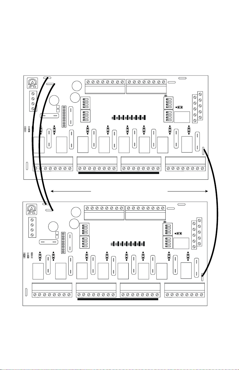
Daisy Chaining Two (2) ACMS8(CB) Dual Output Access Power Controllers:
Use 18 AWG or larger UL Listed wire equipped with 1/4” UL Recognized quick connect terminals rated for
proper voltage/current for all jumper connections.
1. Connect first ACMS8(CB) board’s spade lug marked [PWR1 +] to the second ACMS8(CB) board’s spade lug
marked [PWR1 +].
2. Connect first ACMS8(CB) board’s spade lug marked [COM –] to the second ACMS8(CB) board’s spade lug
marked [COM –].
3. Connect first ACMS8(CB) board’s spade lug marked [PWR2 +] to the second ACMS8(CB) board’s spade
lug marked [PWR2 +].
Fig. 4
+INP2--+INP1-- +INP3-- +INP4-- +INP5-- +INP6--+INP7--+INP8--
1
2
3
4
ON
5
6
7
8
ON
INP Logic
<-- >
NO
PWR1
<-- >
PWR2
3
OUT1
OUT2
OUT3
OUT4
PWR1
NC
<-- >
PWR2
PWR1
<-- >
PWR2
3
PWR1+
PWR2+
FACP
1
2
3
4
ONON
EOL JMP
OUT5
OUT6
OUT7
3
5
OUT8
6
7
8
PWR1
FACP
<-- >
EN
DIS
<-- >
PWR2
3
3
FACP
C GND GND -F -R
NC RST EOL +F +R
FACP
3
COM--
+PWR1-- +PWR2--
PWR2
OFF
Brooklyn, NY 11220
Altronix Corp.
COM--
ACMS8
ACMS8CB
PWR1
Power 2
PWR1
<-- >
PWR2
PWR2+
3
3
PWR1+
Power 1
3
3
Output 1 Output 2
NO C NC COM NO C NC COM
+PWR1-- +PWR2--
ACMS8
ACMS8CB
Power 2
PWR1
PWR1
PWR2
OFF
<-- >
Brooklyn, NY 11220
PWR2
Altronix Corp.
COM--
Output 1 Output 2
NO C NC COM NO C NC COM
PWR2+
3
3
PWR1+
RISK OF FIRE REPLACE FUSES WITH SAME TYPE AND RATING
Output 3 Output 4
NO C NC COM NO C NC COM
Output 5Output 6
NO C NC COM NO C NC COM
Jumper Wires with Spade Lugs
+INP2--+INP1-- +INP3-- +INP4-- +INP5-- +INP6--+INP7-- +INP8--
1
2
3
4
ON
Power 1
3
3
5
6
7
8
ON
INP Logic
<-- >
NO
PWR1
<-- >
PWR2
3
RISK OF FIRE REPLACE FUSES WITH SAME TYPE AND RATING
Output 3 Output 4
NO C NC COM NO C NC COM
OUT1
OUT2
OUT3
OUT4
OUT5
PWR1
NC
<-- >
PWR2
PWR1
<-- >
PWR2
3
3
Output 5Output 6
NO C NC COM NO C NC COM
Output 7Output 8
NO C NC COM NO C NC COM
PWR1+
PWR2+
FACP
1
2
3
4
ONON
EOL JMP
OUT6
OUT7
5
OUT8
6
7
8
PWR1
FACP
<-- >
EN
DIS
<-- >
PWR2
3
3
Output 7Output 8
NO C NC COM NO C NC COM
FACP
C GND GND -F -R
NC RST EOL +F +R
FACP
3
COM--
ACMS8/CB Sub-Assembly - 5 -
Page 6
Maximum Output of Altronix Power Supplies:
UL Listed or Recognized Power Supply Output Voltage Max. Output Current
AL400ULXB2
AL600ULXB
AL1012ULXB
AL1024ULXB2
eFlow4NB
eFlow6NB
eFlow102NB
eFlow104NB
VR6
12VDC or 24VDC 12VDC @ 4A or 24VDC @ 3A
12VDC or 24VDC 6A
12VDC 10A
24VDC 10A
12VDC or 24VDC 4A
12VDC or 24VDC 6A
12VDC 10A
24VDC 10A
5VDC or 12VDC 6A
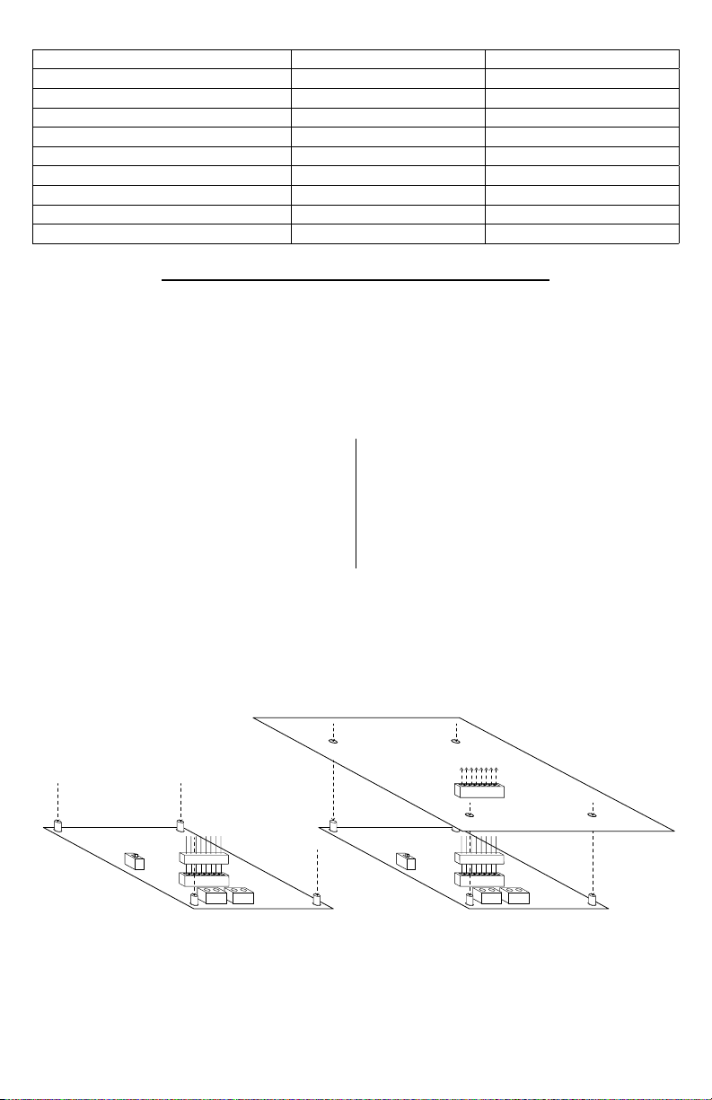
VR6 - Voltage Regulator
VR6 voltage regulator converts a 24VDC input into a regulated 5VDC or 12VDC output. It is specifically
designed to work with ACMS8(CB) by allowing to mount the Access Power Controller directly on top of VR6
to save enclosure space and simplify connections. Refer to VR6 Installation Guide Rev. 050517.
Power Input / Output:
• Input: 24VDC @ 1.75A – Output: 5VDC @ 6A.
• Input: 24VDC @ 3.5A – Output: 12VDC @ 6A.
Output:
• 5VDC or 12VDC regulated output.
• Output rating 6A max.
• Surge suppression.
Connecting ACMS8(CB) to VR6:
1. Mount VR6 in the desired location/enclosure.
2. Plug-in male 8-pin connector to female 8-pin receptacle on VR6 board.
3. Fasten standoffs. Use metal standoff over mounting hole with star pattern.
4. Align 8-pin male connector with female receptacle of ACMS8(CB), then mount.
5. Connect 24VDC power supply to terminal marked [+ PWR1 –] of ACMS8(CB). Thus Input 1 of ACMS8(CB)
is 24VDC from power supply and Input 2 is determined by VR6’s settings (5VDC or 12VDC).
6. Complete steps 4-10 (pgs. 3-4).
Fig. 5
Overview:
Specifications:
LED Indicators:
• Input and output LEDs.
Electrical:
• Operating temperature: 0ºC to 49ºC ambient.
• Humidity: 20 to 93%, non-condensing.
Mechanical:
• Product weight (approx.): 0.4 lb. (0.18 kg).
• Shipping weight (approx.): 0.5 lb. (0.23 kg).
ACMS8/ACMS8CB
VR6VR6
--
--
+ OUT
+ IN
- 6 - ACMS8/CB Sub-Assembly
--
--
+ OUT
+ IN
Page 7
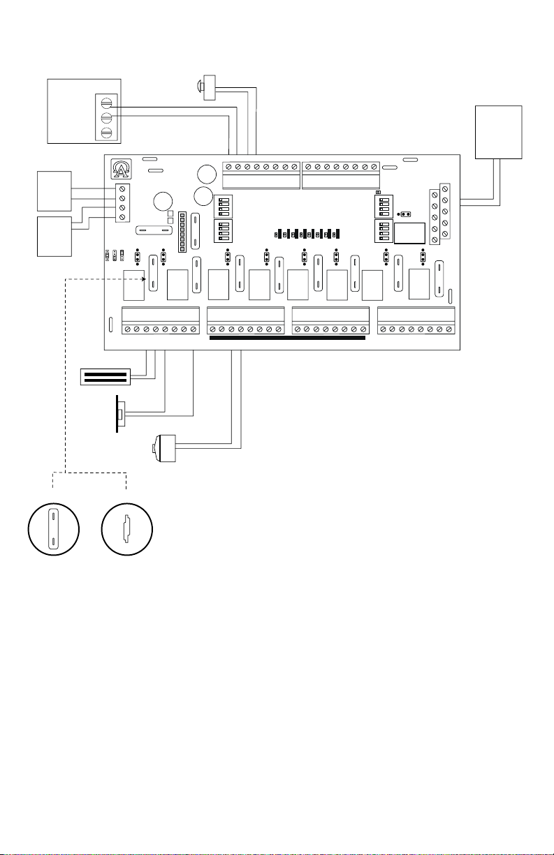
Fig. 6
Power
Supply
(req'd.)
Power
Supply
(optional)
Access Control Panel
C
Output
NO
Relay
NC
DC
DC
Mag. Lock
Electric
Strike
+PWR1-- +PWR2--
ACMS8
ACMS8CB
Power 2
PWR1
PWR1
PWR2
OFF
<-- >
PWR2
Brooklyn, NY 11220
Altronix Corp.
COM--
Output 1 Output 2
NO C NC COM NO C NC COM
Typical Application Diagram:
Normally Open (N.O.)
Door Releasing Device
+INP2--+INP1-- +INP3-- +INP4-- +INP5-- +INP6-- +INP7-- +INP8--
1
2
3
4
ON
5
6
7
8
ON
INP Logic
NO
PWR1
<-- >
PWR2
RISK OF FIRE REPLACE FUSES WITH SAME TYPE AND RATING
Output 3 Output 4
NO C NC COM NO C NC COM
OUT1
OUT2
PWR1
<-- >
NC
<-- >
PWR2
3
3
PWR2+
3
PWR1+
Power 1
3
3
3
OUT3
OUT4
OUT5
OUT6
OUT7
OUT8
PWR1
<-- >
PWR2
3
3
Output 5 Output 6
NO C NC COM NO C NC COM
PWR1+
PWR2+
FACP
1
2
3
4
ONON
5
6
7
8
PWR1
FACP
<-- >
EN
DIS
<-- >
PWR2
NO C NC COM NO C NC COM
EOL JMP
3
Output 7 Output 8
FACP
(Fire Alarm
Control
Panel)
FACP
C GND GND -F -R
NC RST EOL +F +R
FACP
3
COM--
Electromagnetic
Door Holders
ACMS8CBACMS8
3
ACMS8/CB Sub-Assembly - 7 -
Page 8
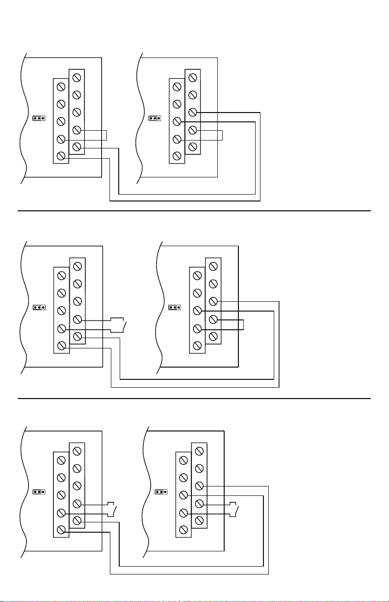
Hook-Up Diagrams:
Fig. 7 - Daisy-chaining one or more ACMS8 units.
EOL Jumper [EOL JMP] should be installed in the EOL position. Non-Latching.
FACP
EOL JMPEOL JMP
C GND GND -F -R
NC RST EOL +F +R
FACP
FACP
JumperJumper
C GND GND -F -R
NC RST EOL +F +R
FACP
Fig. 8 - Daisy-chaining one or more ACMS8 units.
EOL Jumper [EOL JMP] should be installed in the EOL position. Latching Single Reset.
FACP
FACP
N.O.
Switch
C GND GND -F -R
NC RST EOL +F +R
EOL JMPEOL JMP
FACP
Jumper
C GND GND -F -R
NC RST EOL +F +R
FACP
Fig. 9 - Daisy chaining one or more ACMS8 units.
EOL Jumper [EOL JMP] should be installed in the EOL position. Latching Individual Reset.
FACP
N.O.
Switch
C GND GND -F -R
NC RST EOL +F +R
FACP
- 8 - ACMS8/CB Sub-Assembly
EOL JMPEOL JMP
FACP
FACP
N.O.
Switch
C GND GND -F -R
NC RST EOL +F +R
Page 9
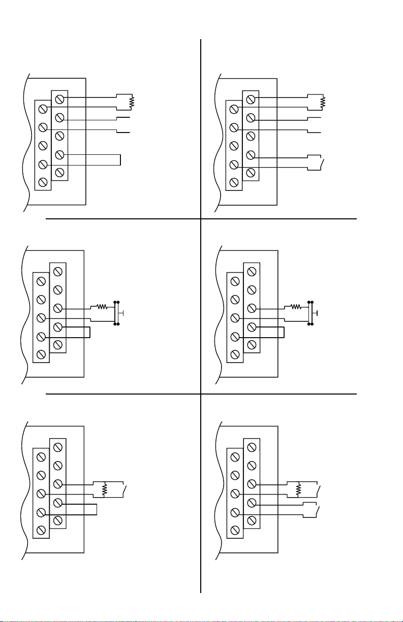
Hook-Up Diagrams:
Fig. 10 - Polarity reversal input from FACP
signaling circuit output (polarity is
referenced in alarm conditiion).
Non-Latching.
Fig. 11 - Polarity reversal input from FACP
signaling circuit output (polarity is
referenced in alarm condition).
Latching.
FACP
EOL
+ --
Jumper
C GND GND -F -R
NC RST EOL +F +R
FACP
Fig. 12 - Normally Closed trigger input
(Non-Latching).
FACP
10K
EOL
Jumper
C GND GND -F -R
NC RST EOL +F +R
FACP
FACP
EOL
+ --
N.O.
C GND GND -F -R
NC RST EOL +F +R
FACP
Switch
Fig. 13 - Normally Closed trigger input
(Latching).
FACP
10K
EOL
Jumper
C GND GND -F -R
NC RST EOL +F +R
FACP
Fig. 14 - Normally Open trigger input
(Non-Latching).
FACP
N.O.
EOL
Switch
Jumper
C GND GND -F -R
NC RST EOL +F +R
FACP
ACMS8/CB Sub-Assembly - 9 -
Fig. 15 - Normally Open trigger input
(Latching).
FACP
N.O.
EOL
Switch
N.O.
C GND GND -F -R
NC RST EOL +F +R
FACP
Switch
Page 10

Notes:
- 10 - ACMS8/CB Sub-Assembly
Page 11

Notes:
ACMS8/CB Sub-Assembly - 11 -
Page 12

Notes:
Altronix is not responsible for any typographical errors.
140 58th Street, Brooklyn, New York 11220 USA | phone: 718-567-8181 | fax: 718-567-9056
website: www.altronix.com | e-mail: info@altronix.com | Lifetime Warranty | Made in U.S.A.
IIACMS8/ACMS8CB I05R
- 12 - ACMS8/CB Sub-Assembly
MEMBER
 Loading...