

Page 1

ACM4 Series
Access Power Controllers
Installation Guide
Models Include:
ACM4
- Four (4) Fuse Protected Outputs
ACM4E
- Four (4) Fuse Protected Outputs w/Enclosure
ACM4CB
- Four (4) PTC Protected Outputs
ACM4CBE
- Four (4) PTC Protected Outputs w/Enclosure
Rev. 082808
More than just power.
TM
Page 2
Overview:
These units convert one (1) 12 to 24 volt AC or DC input into four (4) independently controlled fused or PTC protected
outputs. These power outputs can be converted to dry form “C” contacts (ACM4/ACM4E only). Outputs are activated by
an open collector sink or normally open (NO) dry trigger input from an Access Control System, Card Reader, Keypad, Push
Button, PIR, etc. The units will route power to a variety of access control hardware devices including Mag Locks, Electric
Strikes, Magnetic Door Holders, etc. All interconnecting devices must be UL Listed. Outputs will operate in both Fail-Safe
and/or Fail-Secure modes. Units are designed to be powered by one common power source which will provide power for
both the board operation and locking devices, or two (2) totally independent power sources, one (1) providing power for
board operation and the other for lock/accessory power. The FACP Interface enables Emergency Egress, Alarm Monitoring,
or may be used to trigger other auxiliary devices. The fire alarm disconnect feature is individually selectable for any or all
of the four (4) outputs.
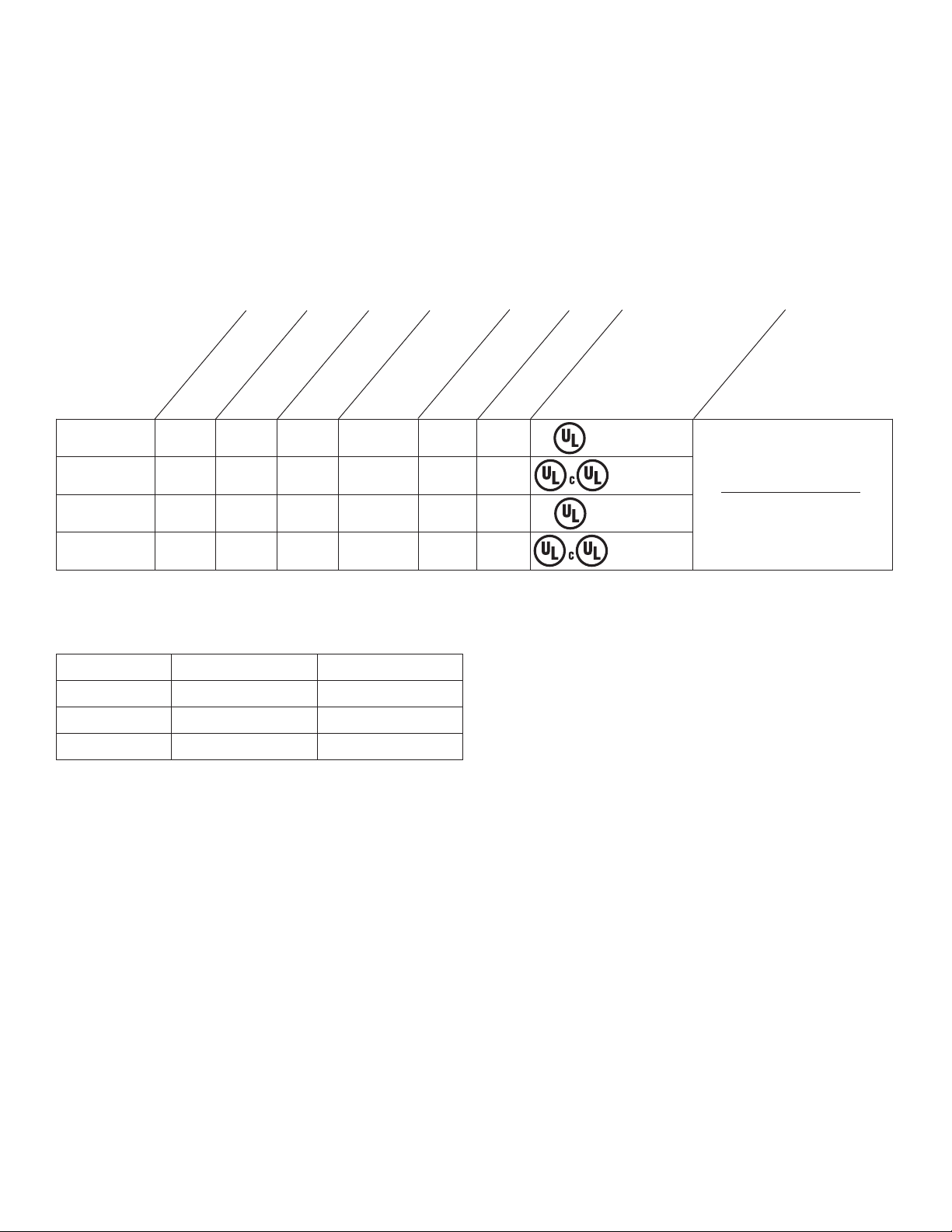
Configuration Reference Chart:
Altronix
Model
Number
ACM4 4 x ---- 3 amp - *
ACM4E 4 x ---- 3 amp - x
Outputs
Number of
Fuse Protected
Outputs
PTC Protected
Outputs
Output Ratings
(per output)
Class 2 Rated Power
Limited Outputs
Enclosure
Agency Listings
UL Listed
Sub-Assembly.
UL Listed
Accessory.
UL Listings and
File Numbers
UL File # BP6714
UL Listed for Access Control
System Units (UL 294).
ACM4CB 4 ---- x 2 amp x *
ACM4CBE 4 ---- x 2 amp x x
UL Listed
Sub-Assembly.
UL Listed
Accessory.
“Signal Equipment” Evaluated to
CSA Standard C22.2
No.205-M1983
*Install in Altronix Power Supply/Chargers AL300ULX, AL400ULX and AL600ULX only. Total output current when
ACM4/ACM4CB is utilized as a sub-assembly with power supply/chargers listed below (see Total Output Chart, below).
Note: The total for all outputs combined is not to exceed 8 amp for ACM4CBE and 10 amp for
ACM4E.
Total Output Chart:
Power Supply 12 volt DC Output 24 volt DC Output
AL300ULX 2.1 amp 2.3 amp
AL400ULX 2.8 amp 3.6 amp
AL600ULX 5.6 amp 5.8 amp
Note: ACM4/ACM4CB can only be utilized with the power supplies listed above.
Specifications:
• 12 to 24volt AC or DC operation (setting not required).
• Input Ratings (ACM4/ACM4CB only):
- 12VDC @ .4 amp or 24VDC @ .2 amp.
Input Ratings (ACM4E/ACM4CBE only):
- 12VDC @ .4 amp or 24VDC @ .2 amp.
- 12VAC @ .4 amp or 24VAC @ .3 amp.
• Power supply input options:
a) One (1) common power input (board and lock power).
b) Two (2) isolated power inputs (one (1) for board power and one (1) for lock/hardware power).
• Four (4) Access Control System trigger inputs:
a) Four (4) normally open (NO) inputs.
b) Four (4) open collector sink inputs.
c) Any combination of the above.
• Four (4) independently controlled outputs:
a) Four (4) Fail-Safe and/or Fail-Secure power outputs.
b) Four (4) dry form “C” 5 amp rated relay outputs (ACM4/ACM4E only).
c) Any combination of the above (ACM4/ACM4E only).
• Four (4) auxiliary power outputs (unswitched).
- 2 - ACM4 series
Page 3

• Output ratings:
- Fuses are rated 3 amp each.
- PTCs are rated 2.5 amp each.
• Main fuse is rated at 10 amp.
Note: The total for all outputs combined is not to exceed 8 amp for ACM4CBE and 10 amp for ACM4E.
(For Models ACM4/ACM4CB refer to the Total Output Chart on Page 2).
Note: Operating temperature range should be 0 to +49
o
C.
• Red LEDs indicate outputs are triggered (relays energized).
• Fire Alarm disconnect (latching or non-latching) is individually selectable for any or all of the four (4) outputs.
Fire Alarm disconnect input options:
a) Normally open (NO) or normally closed (NC) dry contact input.
b) Polarity reversal input from FACP signaling circuit.
• FACP output relay (form “C” contact rated @ 1 amp 28VDC not evaluated by UL).
• Green LED indicates when FACP disconnect is triggered.
• Removable terminal blocks facilitate ease of installation.
Board Dimensions (approximate): 5.125”L x 3.625”W x 1.25”H (ACM4 and ACM4CB).
Enclosure Dimensions (approximate): 8.5”H x 7.5”W x 3.5”D (ACM4E and ACM4CBE).
Installation Instructions:
Wiring methods shall be in accordance with the National Electrical Code/NFPA 70/ANSI, and with all local codes and
authorities having jurisdiction. Product is intended for indoor use only.
1. For ACM4/ACM4CB sub-assembly boards, use stand-offs to mount only in AL300ULX, AL400ULX or
AL600ULX enclosures (Figs. 8-9, pg. 8). For ACM4E/ACM4CBE units, mount in desired location.
The enclosure door for the ACM4E/A
Mark and predrill holes in the wall to line up with the top two keyholes in the enclosure. Install three upper
fasteners and screws in the wall with the screw heads protruding. Place the enclosure’s upper keyholes over the two
upper screws, level and secure. Mark the position of the lower three holes. Remove the enclosure. Drill the lower
holes and install the two fasteners. Place the enclosure’s upper keyholes over the two upper screws. Install the
two lower screws and make sure to tighten all screws (Enclosure Dimensions, pg. 7).
Carefully review:
Typical Application Dia
gram (pg. 4) Terminal Identification Table (pg. 5)
LED Diagnostics (pg. 5) Hook-up Diagrams (pg. 6)
2. Power supply input:
The units can be powered with one (1) Listed Access Control Power Supply which will provide power for both
board operation and the locking devices or two (2) separate Listed Access Control Power Supplies, one (1) to provide
po
wer for the board operation and the other to provide power for the locking devices and/or access control hardware.
Note: The input power can be either 12 to 24 volts AC or DC operation.
Input Ratings (ACM4/A
CM4CB only):
- 12VDC @ .4 amp or 24VDC @ .2 amp.
Input Ratings (ACM4E/ACM4CBE only):
- 12VDC @ .4 amp or 24VDC @ .2 amp.
- 12VAC @ .4 amp or 24VAC @ .3 amp.
(a) Single power supply input:
If the unit and the locking devices are to be powered using a single Listed Access Control Power Supply, connect
the output (12 to 24 v
(b) Dual po
wer supply inputs (Fig. 1, pg. 4):
olts AC or DC) to the terminals marked [- Control +].
When the use of two Listed Access Control P
of the power/control terminals) must be cut. Connect power for the unit to the terminals marked [- Control +]
and connect power for the locking devices to the terminals marked [- Power +].
Note: When using DC Listed Access Control Power Supplies polarity must be observed. When using AC Listed
Access Control P
ower Supplies polarity need not be observed.
Note: For UL compliance the power supplies must be UL Listed for Access Control Systems and accessories.
3. Output options (Fig. 1, pg. 4):
The ACM4/ACM4E will provide either four (4) switched power outputs, four (4) dry form “C” outputs, or
an
y combination of of both switched power and form “C” outputs, plus four (4) unswitched auxiliary power outputs.
The ACM4CB/ACM4CBE will provide four (4) switched power outputs or four (4) unswitched auxiliary power outputs.
(a) Switched Power outputs:
Connect the negative (-) input of the device being powered to the terminal marked [COM]. For Fail-Safe operation
ACM4 series - 3 -
CM4CBE can be fastened by using either a cam lock or screws (both supplied).
ower Supplies is desired, jumpers J1 and J2 (located to the left
Page 4

connect the positive (+) input of the device being powered to the terminal marked [NC]. For Fail-Secure operation
NC C NO COM
OUTPUT1
NC C NO COM
OUTPUT2
NO C NC
FACP
--- + --- +
Power Control
+ INP --- T + RET ---
INTERFACE
L
ED1
S
W1 SW2 SW3
S
W4
L
ED2 LED3 LED4
TRIGGER
INPUT
T
RG
NC C NO COM
OUTPUT3
NC C NO COM
OUTPUT4
J2 J1
J
3
ACM4
A
CCESS POWER
CONTROLLER
LED1
SW1 SW2
LED2
IN GND
2
IN GND
1
IN GND
3
IN GND
4
NC
NO
C
KEYPAD
NORMALLY OPEN
N.O. DOOR
RELEASING
DEVICE
ACCESS CONTROL
PANEL
OUTPUT
RELAY
MAG.
LOCK
MAG.
LOCK
ELECTRIC
STRIKE
ELECTROMAGNETIC
DOOR HOLDERS
LISTED
AC or DC
ACCESS CONTROL
POWER SUPPLY
(optional)
FACP
(Fire Alarm
Control Panel)
LISTED
AC or DC
ACCESS CONTROL
POWER SUPPLY
(req’d)
UL Listed Power-Limited Power Supply
For this application
corresponding fuse
must be removed.
(ACM4 and ACM4E only)
FACP Interface Enabled
FACP Interface Disabled
SW1-SW4
ACM4CB
FACP Dry
Form "C"
Output
NO C NC
FACP
3A
1
0A
3A3A3A
Keep power limited wiring separate from non-power limited.
Use minimum .25" spacing.
connect the positive (+) input of the device being powered to the terminal marked [NO].
(b) Form “C” outputs (ACM4/ACM4E):
When form “C” outputs are desired the corresponding output fuse (1-4) must be removed. Connect negative (-) of
the po
wer supply directly to the locking device. Connect the positive (+) of the power supply to the terminal marked
[C]. For Fail-Safe operation connect the positive (+) of the device being powered to the terminal marked NC]. For
Fail-Secure operation connect the positive (+) of the device being powered to the terminal marked [NO].
(c) Auxiliary Power outputs (unswitched):
Connect positive (+) input of the device being powered to the terminal marked [C] and the negative (-) of the device
being po
wered to the terminal marked [COM]. Output can be used to provide power for card readers, keypads etc.
Note: When wiring for power-limited outputs utilize a knockout separate from the one used for
non po
wer-limited wiring.
4. Input trigger options (Fig. 1, pg. 4):
(a) Normall
y Open [NO] input trigger:
Inputs 1-4 are activated by normally open or open collector sink inputs.
Connect de
vices (card readers, keypads, request to exit buttons etc.) to terminals marked [IN] and [GND].
(b) Open Collector Sink inputs:
Connect the access control panel open collector output to the terminal marked [IN] and the
common (ne
gative) to the terminal marked [GND].
Typical Application Diagram:
Fig. 1a
Fig. 1
- 4 - ACM4 series
Page 5

5. Fire Alarm Interface options (Figs. 3 through 7, pg. 6):
A nor
mally closed [NC], normally open [NO] input or polarity reversal input from FACP signaling circuit will
trigger selected outputs. To enable FACP Disconnect for an output open the corresponding switch [SW1-SW4].
To disable FACP disconnect for an output close the corresponding switch [SW1-SW4].
(a) Normally Open [NO] input:
For non-latching hook-up (Fig. 4, pg. 6). For latching hook-up (Fig. 5, pg. 6).
(b) Normally Closed [NC] input:
For non-latching hook-up (Fig. 6, pg. 6). For latching hook-up (Fig. 7, pg. 6).
(c) FACP Signaling Circuit input trigger:
Connect the positive (+) and negative (-) from the FACP signaling circuit output to the terminals marked [+ INP -].
Connect the F
ACP EOL to the terminals marked [+ RET -] (polarity is referenced in an alarm condition).
Jumper J3 must be cut (Fig. 3, pg. 6).
6. FACP Dry form “C” output (Fig. 1a, pg. 4):
Connect desired device to be triggered by the unit’s dry contact output to the terminals marked [NO] and [C]
F
ACP for normally open output or the terminals marked [NC] and [C] FACP for normally closed output.
7. Installation of tamper switch (Not Included):
Mount UL Listed tamper switch (Sentrol model 3012 or equivalent) at the top of the enclosure. Slide the tamper
switch brack
et onto the edge of the enclosure approximately 2” from the right side.
Connect tamper switch wiring to the Listed Access Control Panel input or the appropriate UL Listed reporting device,
to activate alarm signal when the door of the enclosure is open.
Maintenance:
Unit should be tested at least once a year for the proper operation. Voltage on each output has to be tested for both
trigger and non-trigger states and operation of FACP interface has to be simulated.
LED Diagnostics:
LED ON OFF
LED 1 - LED 4 (Red) Output relay(s) energized. Output relay(s) de-energized.
TRG (Green) FACP input triggered (alarm condition). FACP normal (non-alarm condition).
Terminal Identification Tables:
Terminal Legend Function/Description
-- Power + 12VDC to 24VDC input from UL Listed Access Control Power Supply.
These terminals can be connected to a separate, UL Listed Access Control Power Supply to
-- Control +
TRIGGER
INPUT 1 - INPUT 4
IN, GND
OUTPUT 1 - OUTPUT 4
NC, C, NO, COM
provideisolated operating power for the ACM4/ACM4E/ACM4CB/ACM4CBE (jumpers
J1and J2 Must be removed).
From normally open and/or open collector sink trigger inputs
(request to exit buttons, exit pir’s, etc.).
12 to 24 volts AC/DC trigger controlled outputs:
Fail-Safe [NC positive (+) & COM Negative (-)],
Fail-Secure [NO positive (+) & COM Negative (-)],
Auxiliary output [C positive (+) & COM Negative (-)]
(When using AC power supplies polarity need not be observed),
NC, C, NO become form “C” 5 amp 24VAC/VDC rated dry outputs when fuses are
removed (ACM4/ACM4E). Contacts shown in a non-triggered state.
FACP INTERFACE
T, + INPUT --
FACP INTERFACE
NC, C, NO
ACM4 series - 5 -
Fire Alarm Interface trigger input from FACP. Trigger inputs can be normally open,
normally closed from an FACP output circuit (Fig. 3 through 7, pg. 6).
Form “C” relay contact rated @ 1 amp 28VDC for alarm reporting.
(This output has not been evaluated by UL).
Page 6

NO C NC
FACP
+ INP --- T + RET ---
INTERFACE
TRG
J3
JUMPER
N.C. DRY
TRIGGER
INPUT
NO C NC
FACP
+ INP --- T + RET ---
INTERFACE
TRG
J3
N.C. TRIGGER
INPUT
N.C. RESET
SWITCH
JUMPER
Fig. 2 Optional hook-up using two (2) isolated
CUT JUMPERS
J1 AND J2
ISOLATED POWER INPUT
1
2 OR 24VAC OR VDC
(LOCK POWER)
ISOLATED POWER INPUT
1
2 OR 24VAC OR VDC
(ACM4 POWER)
--- + --- +
Power Control
J2 J1
CUT
JUMPER J3
FROM FACP
CONTROL
CIRCUIT
+
--
FACP
CONTROL
CIRCUIT EOL
(if employed)
NO C NC
FACP
+ INP --- T + RET ---
INTERFACE
TRG
J3
NO C NC
FACP
+ INP --- T + RET ---
INTERFACE
TRG
J3
N.O. TRIGGER
INPUT
NO C NC
FACP
+ INP --- T + RET ---
INTERFACE
TRG
J3
N.C. RESET
SWITCH
N.O.
TRIGGER
INPUT
JUMPER
po
wer supply inputs:
Hook-up Diagrams:
. 3 Polarity reversal input from FACP signaling circuit
Fig
output (polarity is referenced in alarm condition):
(This output has not been evaluated by UL)
Fig. 4 Normally Open - Non-Latching FACP
trigger input:
Fig. 6 Normally Closed - Non-Latching FACP
trigger input:
Fig. 5 Normally Open FACP Latching trigger input
with reset:
(This output has not been evaluated by UL)
Fig. 7 Normally Closed - Latching FACP trigger input
with reset:
(This output has not been ev
aluated by UL)
Note: Keep power limited wiring separate from non-power limited. Use minimum .25" spacing.
- 6 - ACM4 series
Page 7

• ACM4E and ACM4CBE
8.5"H x 7.5"W x 3.5"D
Enclosure Dimensions:
ACM4 series - 7 -
Page 8

UL Listed Sub-Assembly Installation Instructions:
NC C NO COM
OUTPUT1
NC C NO COM
OUTPUT2
NO C NC
FACP
--- + --- +
Power Control
+ INP --- T + RET ---
INTERFACE
LED1
SW1 SW2
SW3
SW4
LED2 LED3 LED4
10A
3A3A3A3A
TRIGGER
INPUT
TRG
NC C NO COM
OUTPUT3
NC C NO COM
OUTPUT4
J2 J1
J3
IN GND
2
IN GND
1
IN GND
3
IN GND
4
--- DC
+
L G N
NC C NO NC C NO
+ BAT ---
AC FAIL
BAT FAIL
S
ub-Assembly
M
ounting
Holes
Divider
Red Lead
Black Lead
P
ower Supply Board for:
AL300ULX(R)
AL400ULX(R)
A
L600ULX(R)
--- + --- +
Power Control
Keep power limited wiring separate
from non-power limited.
Use minimum .25" spacing.
Screw
Sub-Assembly
Stand-off
Stud
Enclosure
NC C NO COM
OUTPUT1
NC C NO COM
OUTPUT2
NO C NC
FACP
--- + --- +
Power Control
+ INP --- T + RET ---
INTERFACE
LED1
SW1 SW2 SW3
SW4
LED2 LED3 LED4
TRIGGER
INPUT
TRG
NC C NO COM
OUTPUT3
NC C NO COM
OUTPUT4
J2 J1
J3
IN GND
2
IN GND
1
IN GND
3
IN GND
4
10A
The following Altronix sub-assembly modules may be field installed in the AL300ULX(R), AL600ULX(R),
AL400ULX(R) power supply/chargers: ACM4 or ACM4CB
1. Disconnect power before proceeding with sub-assembly installation.
2. Fasten stand-offs (supplied) to the corresponding studs in the enclosure.
3. Align mounting holes of sub-assembly with stand-offs (Fig. 8, pg. 8).
Refer below for the location and position for placement of sub-assembly.
4. Fasten sub-assembly to enclosure using the four (4) screws (supplied) (Fig. 9, pg. 8).
5.
Connect red and black power leads of CM type jacketed wire (supplied), as shown below:
Terminals
P
ower Leads Power Supply Sub-Assembly
(provided) Output Input
Red Lead DC + Control +
Black Lead DC -- Control --
Fig. 9
Enclosure Dimensions:
13.5”H x 13”W x 3.25”D
Fig. 8
Mounting Position for
UL Listed Sub-Assembly Installation.
ACM4
ACM4CB
Altronix is not responsible for any typographical errors.
Altronix Corp.
140 58th Street, Brooklyn, New York 11220 USA, 718-567-8181, fax: 718-567-9056
web site: www.altronix.com, e-mail: info@altronix.com, Lifetime Warranty, Made in U.S.A.
IIACM4/ series J09H
- 8 - ACM4 series
MEMBER
 Loading...