

Page 1

MODEL: MS1
Page 2

CONTENT
1. INTRODUCTION.................................................................... ..........1
2. TECHNICAL SPECIFICATION ........................................................1
3. BLOCK DIAGRAM..........................................................................2
4. SCHEMATIC DIAGRAM..................................................................3
5. PCB LAYOUT..................................................................................4
6. TEST PROCEDURE........................................................................5
7. EXPLODED VIEW & MECHANICAL PARTS LIST.........................15
8. BOM ..............................................................................................17
Page 3
z 16 effects preset
1. INTRODUCTION
2. TECHNIACAL SPECIFICATION
- 1 -
z 2-channel input and output connectors are compatible with balanced JACK
z Front panel LED indicator for clip and power on
z Accurate level control
Connectors 1/4”jack
Type RF filtered, servo balanced input
AUDIO INPUT
Impedance 30 Kohm balanced, 22 Kohm unbalanced
Max. input level +26 dBu balanced and Unbalanced
CMRR Typ. 40dB,>55dB@1 kHz
Connectors 1/4” jack
Type Balanced
AUDIO OUTPUT
Min. output impedance 100 Ohm
Max. output level +26 dBu balanced
Frequency response 10Hz to 30kHz, +/-1dB(FLAT)
SYSTEM
S/N >110dB, unweighted, 22Hz to 22kHz
SPECIFICATIONS
THD 0.005% typ.@ 0 dBu, 1khz, (unity gain), FLAT
INDICATORS Input level CLIP LED display: +7dBu
AC adaptor USA/Canada 120V~, 60Hz
U.K./Australia 240v~, 50Hz
POWER SUPPLY
Europe 230V~, 50Hz
Power consumption 5W
Dimension 130(W)×117(D)×45(H)mm(5.1”×4.6” ×1.7”)
PHYSICAL
Net weight 0.8kg
Page 4
D
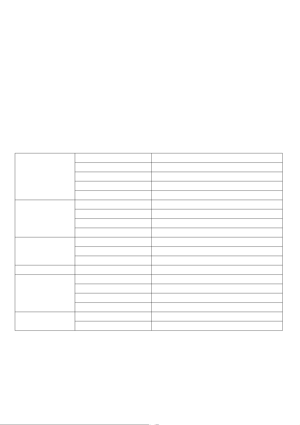
3. BLOCK DIAGRAM
- 2 -
4
C
B
A
CLIP
J2
12345
OUTPUT LCH
6
J4
12345
OUTPUT RCH
6
G
-12V
5
6
321
SIGNAL SENSE
SW1
3
4
4BIT ENCODER
1
2
+12V
12345
J1
ENCODER 4BIT CONTROL
A0 A1 A2 A3
INPUT GAIN
6
INPUTLCH
12345
J3
6
INPUT RCH
AC ADAPTOR
AC 15V 200mA INPUT
A0 A1 A2 A3
+12VDC
-12VDC
1 2 34
POWER SUPPLY
D
C
B
A
Page 5
B
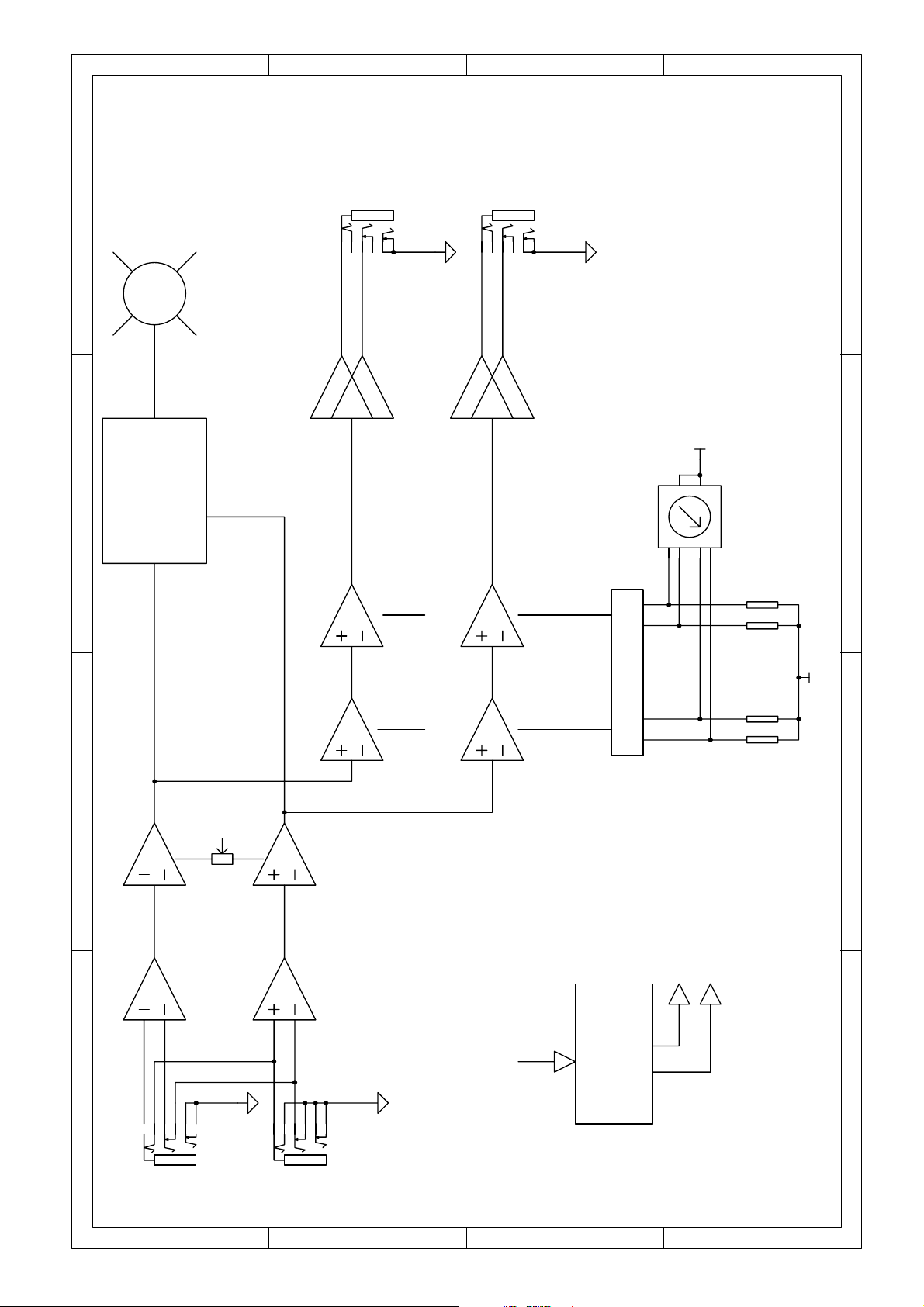
4. SCHEMATIC DIAGRAM
- 3 -
connect to J5 -1
CLIP
LED2
RED
R72
0R 1/4W
LED1
SW1
123
100K
R42
5
100K
R43
C
6
100K
R44
C38
22P
288S0366
4
100K
R45
D
-VCC
+VCC
8
D3
1N5817
C44
220UF/25V
D4
1N5817
-VCC
C45
220UF/25V
connect to J5 -2
R70
3
C15
0.1u c er
+12V
GND
2
7654321
Vin
1
U9
LM7812CT
D1
1N4002
C13
0.1u
123
S1
DJ-005A
1
U8
C42
1000UF/35V
3
C16
0.1u c er
GND
2
LM7912CT
C43
1000UF/35V
D2
C14
0.1u
-12V
Vin
1N4002
+VCC
6
J2
LJB0661-6
R58
100 1/4W
1M
R69
1M
R68
1M
R67
1M
A0A1A2
A3
R63
12345
C34
R62
51K
C63
22P
C33 47U/25V
R21
10.0K
51K
47U/25V
R59
100 1/4W
C69
0.1u c er
R22
10.0K
-VCC
C68
1.0U
C67
1.0U
C66
1.0U
C65
1.0U
6
1
2
J5
CON2
J4
A0~A3:ON=+VCC,OFF=-VCC,DELAY=0.1-1S
1.5K
R17
R71
+VCC
1
3
2
C70
0.1u c er
C48
8 4
+VCC
C2E
3
B
Q2
2SC1815
1
6.8K
2.2U/25V
Q1
2SC1815
C2E
3
B
1
R31
4.7K
LJB0661-6
12345
C41
47U/25V
R65
51K
C64
22P
C40 47U/25V
R60
100 1/4W
7
R24
10.0K
A
+VCC
connect to J6 -1connect to J6 -2
POWER
R73
4.7K 1/4W
RED
R66
51K
R61
100 1/4W
R25
10.0K
-VCC
1
2
J6
CON2
7
U7B
MC33078
5
6
12V 1W
U6B
R19
3.74K
C62
C61
C39
C26
10P
C4
1
C24
0.1u c er
C28
84
3.74K
U6A
+VCC
C60
C59
C31
C2510P
R35
C3
R18
C23
0.1u cer
1
-VCC
3
R12
1.10K
C7
13
VR1A
2
10KB
-VCC
R8
C6 22P
ZD3
22P
12V 1W
7.50K
2
C30
47U/25V
C29
47U/25V
R11
1.10K
C12
0.1u c er
1
3
2
R7
R1
15.0K
7.50K
C22
U2A
MC33078
R15
C11
MC33078
+VCC
0.1u cer
8 4
6.8K
0.1u c er
+VCC
8 4
U1A
C5
22P
R2
15.0K
ZD4
12V 1W
R39
3
1.0U
1.20K
47U/25V
27nF
C57
1.50K
C21
2
1.0U
C19
1000P
-VCC
C18
MC33078
0.1u c er
+VCC
R47
0.1u c er
2
0.1u c er
0.1u cer
-VCC
R48
7.50K
1
U5A
84
3
2
R51
30.0K
7.50K
1
C27
8 4
3
U4A
MC33078
R37
220.0K
C53
10nF
R33
1.0K
R30
4.7K
1
Fc=30hz
MC33078
C55
R41
100K
0.1u c er
+VCC
C32
-12db/OCT
C20
0.1u c er
-VCC
330P
47U/25V
MC33078
Fc=18K
U7A
C37
CLIP LED LIGHT SET=+6dbU
R57
R55
9.1K
R14
1.10K
R53
20K
-12db/OCT
HIGH Fc=18K,LOW Fc=30HZ IS NOT USED,R74=0R
R74
0R*
C8 22P
TR4
J176
TR3
J176
C10
22P
46
C36
VR1B
5
10KB
C35
47U/25V
R10
7.50K
ZD8
12V 1W
9.1K
7
5
6
6
15.0K
U2B
MC33078
47U/25V
R13
1.10K
7
5
U1B
MC33078
R4
R5
47U/25V
R16
6.8K
R9
7.50K
C9
22P
15.0K
ZD7
MC33078
Fc=30hz
5
6
1.0U
R50
1.0U
C58
1000P
R49
7.5K
47U/25V
R40
1.50K
6
R36
1.20K
27nF
-12db/OCT
7.5K
7
R54
20K
U5B
MC33078
Fc=18K
-12db/OCT
5
6
C56
330P
R52
30.0K
HIGH Fc=18K,LOW Fc=30HZ IS NOT USED,R75=0R
R75
0R*
R46
100K
7
5
U4B
MC33078
R38
220.0K
TR8
J176
C54
10nF
R34
1.0K
R32
4.7K
7
TR7
J176
ZD1
12V 1W
L1
IN-CH2+
6
J1
LJB0661-6
balanced input
L2
FL5R
D
ZD2
FL5R
12345
C17
MC33078
R3
220nF
0.1u c er
8 4
+VCC
U3A
R26
15.0K
C
C47
TR2
J176
2.2U/25V
150.0K
TR1
J176
C46
2.2U/25V
A0 A1 A2 A3
ZD5
12V 1W
L3
6
IN-CH2+
J3
LJB0661-6
balanced input
L4
FL5R
IN-CH2-
ZD6
12V 1W
5
6
R29
30.0K
FL5R
12345
B
C2 100nF
R23
10.0K
U3B
MC33078
R27
150.0K
C50
R6
15.0K
C52
220nF
C49
2.2U/25V
2.2U/25V
A
J176
TR6
J176
1 2 3 4 5 6 78
TR5
A0 A1 A2 A3
12V 1W
IN-CH2-
C1 100nF
-VCC
3
2
R28
30.0K
R20
10.0K
C51
Page 6
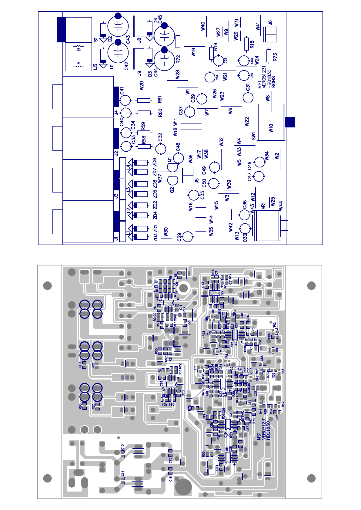
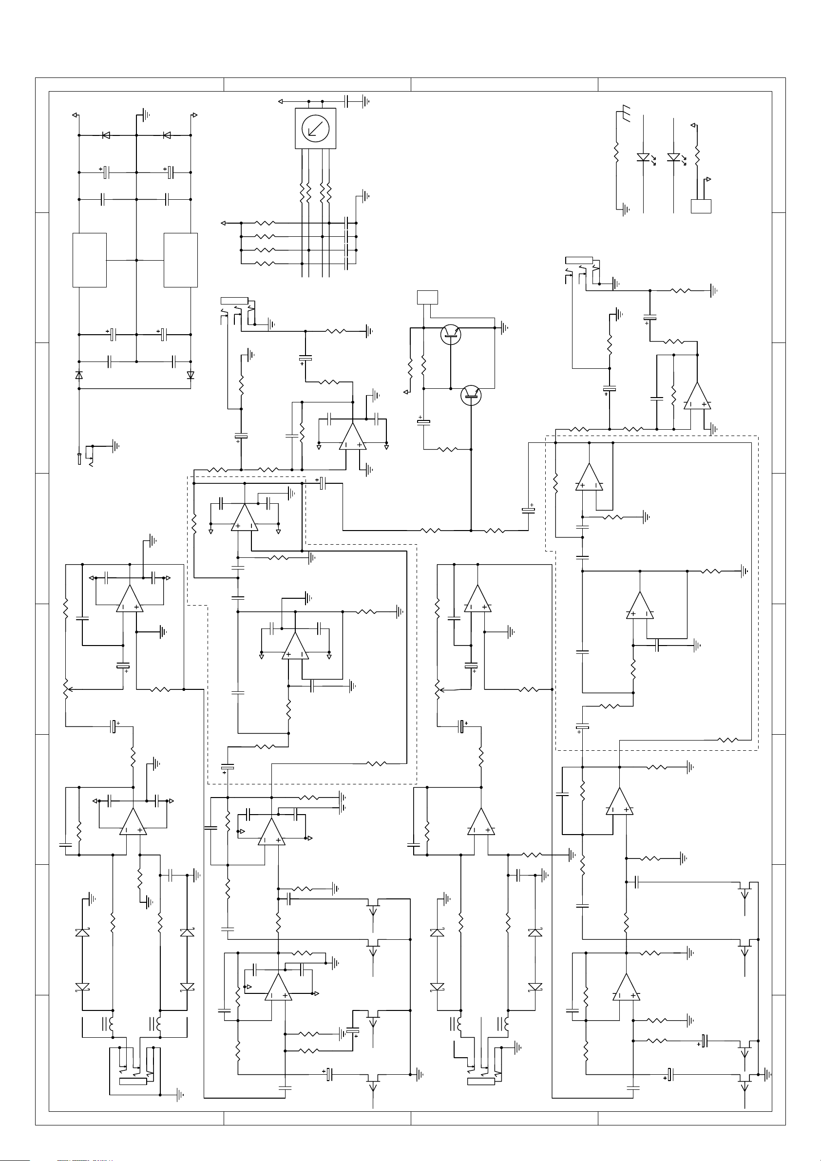
PCB:MS1 Bottom Layer Bttom Overlay Bottom Solder
PCB:MS1 Top Overlay
5. PCB LAYOUT
- 4 -
Page 7
First: Use VP-7724 to test
6. TEST PROCEDURE
The Finished Products Test
- 5 -
1. Set the encoder to FLAT (encoder setting: 0000), INPUT/OUTPUT use 1/4 TRS BAL jack to co nnect
LCH IN, LCH/RCH OUT, plug in POWER&CLIP LED wires(semi product), the red POWER LED
lights up.
2. Input 1KHZ–6dBu(VP-7724 BAL) signal, then adjust INPUT GAIN VR, when INPUT GAIN VR is
minimum, the output is -20+/-2dbu, distortion<0.03%.
3. Adjust INPUT GAIN V R to maximum, the output i s +20+/-2dbu, distortio n<0.01 %( Please select the
corresponding filter when testing distortion).
4. Adjust INPUT GAIN VR, and set the output to +6.5~+8.5dbu, make sure the CLIP LED lights up
slightly.
5. Adjust INPUT GAIN VR, set the output to 0+/-0.2dbu, and also make sure the scale of GAIN VR at
0dB position.
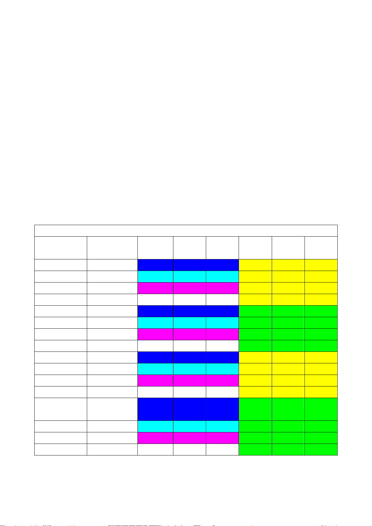
6. According to the following table to test the frequency response, specifications are the following
(altogether 4*4=16 modes), under FLAT mode, make sure the distortion<0.005%.
7. Adjust the input signal to 1 kHz +10dbu, turn GAIN VR from minimum to maximum, make sure the
distortion will become bigger gradually till clipping (FLAT position).
LCH/RCH OUTPUT SPECIFICATION(Test Frequency dBu)
Corresponding
Function
FLAT 0000 -1.0~+1.0 -0.5~+0.5 -0.5~+0.5 -0.5~+0.5 -1.2~+0.8 -5.0~-3.0
DRUM KICK 0001 +9.5~+11.5 +7.5~+9.5 +6.0~8.0 -0.5~+1.0 -1.2~+0.8 -5.0~-3.0
ANTIRUMBLE 0010 -11.5~-9.5 -3.5~-1.5 -2.5~-0.5 -0.5~+0.5 -1.2~+0.8 -5.0~-3.0
CONCERT HALL 0011 -0.5~+1.5 +5.0~+7.0 +4.5~+6.5 -0.5~+1.0 -1.2~+0.8 -5.0~-3.0
ARENA+SUB 0100 -1.0~+1.0 -1.0~+1.0 -0.5~+0.5 +0.2~+1.5 +4.5~+6.5 +1.5~+3.5
LOUDNESS 0101 +9.5~+11.5 +7.5~+9.5 +6.0~8.0 +0.5~+1.5 +4.5~+6.5 +1.5~+3.5
ROCK&ROLL+SUB 0110 -11.5~-9.5 -3.5~-1.5 -2.5~-0.5 +0.5~+1.5 +4.5~+6.5 +1.5~+3.5
ACOUSTIC 0111 -0.5~+1.5 +5.0~+7.0 +4.5~+6.5 +0.5~+1.5 +4.5~+6.5 +1.5~+3.5
JAZZ CLUB+SUB 1000 -1.0~+1.0 -1.0~+1.0 -0.5~+0.5 -0.5~+0.5 -2.0~-0.5 -9.0~-7.0
VIRTUAL SUB 1001 +9.5~+11.5 +7.5~+9.5 +6.0~8.0 -0.0~+0.8 -2.0~-0.5 -9.0~-7.0
STAGE MONITOR 1010 -11.5~-9.5 -3.5~-1.5 -2.5~-0.5 -0.5~+0.5 -2.0~-0.5 -9.0~-7.0
JAZZ CLUB 1011 -0.5~+1.5 +5.0~+7.0 +4.5~+6.5 -0.0~+0.8 -2.0~-0.5 -9.0~-7.0
CONCERT
HALL+SUB
Encoder Setting
20HZ 70HZ 100HZ 1KHZ 8KHZ 20KHZ
(Binary System)
1100 -1.0~+1.0 -1.0~+1.0 -0.5~+0.5 +0.2~+1.5 +3.5~+5.5 -2.0~-0.5
DISCO 1101 +9.5~+11.5 +7.5~+9.5 +6.0~8.0 +0.2~+1.5 +3.5~+5.5 -2.0~-0.5
VOCAL 1110 -11.5~-9.5 -3.5~-1.5 -2.5~-0.5 +0.2~+1.5 +3.5~+5.5 -2.0~-0.5
ROCK&ROLL 1111 -0.5~+1.5 +5.0~+7.0 +4.5~+6.5 +0.2~+1.5 +3.5~+5.5 -2.0~-0.5
Page 8

8. Cut off input signal, when output noise and GAIN VR are minimum, the output noise is less
- 6 -
than-95dBu(Please select the corresponding filter), when the GAIN VR is maximum, the output
noise is less than -78dBu, at the same time, make sure the variations of the waveform are normal
when turning the GAIN VR.
9. Connect OUTPUT to RCH OUT, make su re the R CH output specification is the sam e as above, and
connect the INPUT to RCH IN; also the RCH output specification is the same as above.
10. Listening Test: Input music signal, set the encoder and adjust the GAIN VR, make sure the volume
can change, and also the treble and bass have corresponding variations; cut off the input signal,
make sure the noise sound is normal, set the encoder, make sure the CLICK NOISE is normal.
Second: Use AP to test
1. Set the encoder to FLAT (encoder setting: 0000), INPUT/OUTPUT, use 1/4 TRS Balanced jack to
connect LCH IN, LCH/RCH OUT, plug in POWER&CLIP LED wires(semi product), the red POWER
LED lights up.
2. Input signal is 1KHZ 0dBu (VP-7724 BAL), make sure INPUT GAIN VR is minimum, the output is
-20+/-2dbu, and distortion<0.03%.
3. Adjust INPUT GAIN VR to maximum, the output is +20+/-2dbu, the distortion<0.01 %( It must select
the corresponding filter when test the distortion).
4. Adjust INPUT GAIN VR, set the output to +6.5~+8.5dbu, make sure the CLIP LED lights up slightly at
the moment.
5. Adjust INPUT GAIN V R, set the output to 0+/-0.2dbu, at the same time, make sure the scale of GAIN
VR at 0dB position.
6. According to the following table to test the frequency response, specifications are the following
curves (altogether 4*4=16 modes). In the meantime, make sure the distortion<0.005% under the
FLAT mode.
7. Adjust the input signal to 1 kHz +10dbu, turn GAIN VR from minimum to maximum, and make sure
the distortion will become bigger gradually till clipping (FLAT position).
8. Cut off the input signal, make sure the output noise and GAIN VR are minimum, the output noise is
less than-95dBu (select the corresponding filters), when GAIN VR is maximum, the output noise is
less than -78dBu, at the same time, make sure the variations of the waveform are normal when
turning the GAIN VR.
9. Listening Test: Input music signal, set encoder and adjust the GAIN VR, make sure the volume can
change, and also the treble and bass have the corresponding variation, cut off input signal, make sure
the noise sound is normal, set the encoder, and also make sure the CLICK NOISE is normal.
Page 9

- 7 -
Page 10

- 8 -
Page 11

- 9 -
Page 12

- 10 -
Page 13

- 11 -
Page 14

- 12 -
Page 15

- 13 -
Page 16

- 14 -
Page 17

7. EXPLODED VIEW & MECHANICAL PARTS LIST
- 15 -
Page 18

No. Part No. Description Specification Pcs
MECHANICAL PARTS LIST
- 18 -
1
MA05666
2
SA00053 LED φ3
HK05843 K-PCB P-MS1-DIP
3
4
MB04491
5
NI00502 self-adhere foot cushion φ10.5*5mm(RF-011)
6
NI00002 T-plastic nut-HC00108 accessories φ7/16"*G20/15*4.8
7
ME00081 T-nut-HI00107 φ7
8
MF00014 shakeproof washer φ3*φ6.5*0.5t
9
MG00036 screw M3*4
10
NC00131 T-wooden washer 1*φ11.3*φ15.3 red
11
MC00769 ZC-top cover ALTO MS1
12
NI02386 plastic knob φ14*13mm\
13
NI00363 plastic knob φ21*16mm
14
MG00386 screw M3*4
15
MG00058 screw M2*4
ZC-panel
MS1 ALTO_V1.3
ZC-rear board MS1 ALTO_V1.1
1
2
1
1
4
2
1
3
7
2
1
1
1
2
1
Page 19

No. Part No. Description Specification Remark
8. BOM
- 17 -
1 HK05843 PC board P-MS1-DIP
2 HK06476 PC board P-MS1-SMD
3 RD00125 SMD fixed resistor 1/10W 1.0MΩ ±5% 0603 R67,R68,R69,R70
4 RD00085 SMD fixed resistor 1/10W 1.5KΩ ±5% 0603 R71
5 RD00116 SMD fixed resistor 1/10W 100KΩ ±5% 0603 R41,R42,R43,R44,R45,R46
6 RD00306 SMD fixed resistor 1/10W 20KΩ ±5% 0603 R53,R54
7 RD00093 SMD fixed resistor 1/10W 4.7KΩ ±5% 0603 R30,R31,R32
8 RD00354 SMD fixed resistor 1/10W 51KΩ ±5% 0603 R62,R63,R65,R66
9 RD00097 SMD fixed resistor 1/10W 6.8KΩ ±5% 0603 R15,R16,R17
10 RD00100 SMD fixed resistor 1/10W 9.1KΩ ±5% 0603 R55,R57
11 CI00228
12 CI00071
13 CI00123
14 CI00185
15 CI00075
16 CI00179
17 CI00175
18 CI00047
19 CI00062
20 SF00049 transistor PMBFJ176(SOT23)/(PHI) TR1,TR2,TR3,TR4,TR5,TR6,TR7,TR8
21 RD00282
22 RD00396
23 RD00321
24 RD00201
25 RD00214
26 RD00218
27 RD00457
28 RD00461
29 RD00329
30 RD00213
31 HB01830 PCB MS1_VER051231
32 CI00266
33 SG00558 integrated circuit-RS UTC4580M(4580M )(SOP8)/(YW) U1,U2,U3,U4,U5,U6,U7
SMD ceramic capacitor
0603
SMD ceramic capacitor
0603
SMD ceramic capacitor
0603
SMD ceramic capacitor
0603
SMD ceramic capacitor
0603
SMD ceramic capacitor
0603
SMD ceramic capacitor
0603
SMD ceramic capacitor
0603
SMD ceramic capacitor
0603
SMD precise resistor
1/10W
SMD precise resistor
1/10W
SMD precise resistor
1/10W
SMD precise resistor
1/10W
SMD precise resistor
1/10W
SMD precise resistor
1/10W
SMD precise resistor
1/10W
SMD precise resistor
1/10W
SMD precise resistor
1/10W
SMD precise resistor
1/10W
SMD ceramic capacitorRS 0603
0.001uF/50V C0G±5%(C1608C0G1H102JT)/TDK C57,C58
0.01uF/50V X7R ±10% C53,C54
0.027uF/50V X7R ±10% C3,C4
0.1uF/50V X7R±10%(C1608X7R1H104KT)/TDK C1,C2
0.1uF/50V Y5V +80,-20%
0.22uF/25V X7R±10%(C1608X7R1E224KT)/TDK C51,C52
1.0uF/16V X7R±10%(C1608X7R1C105KT)/TDK C65,C66,C67,C68
10PF/50V C0G±0.25PF(C1608C0G1H100CT)TDK C25,C26
330PF/50V NPO ±5﹪ C55,C56
1.00KΩ ±1% 0603 R33,R34
1.15KΩ ±1% 0603 R11,R12,R13,R14
1.20KΩ ±1% 0603 R35,R36
1.50KΩ ±1% 0603 R39,R40
10.0KΩ ±1% 0603 R20,R21,R22,R23,R24,R25
15.0KΩ ±1% 0603 R1,R2,R3,R4,R5,R6
150KΩ ±1% 0603 R26,R27
220KΩ ±1% 0603 R37,R38
30.0KΩ ±1% 0603 R51,R52,R28,R29
7.50KΩ ±1% 0603 R7,R8,R9,R10,R47,R49
22PF/50V NPO ±5﹪ C5,C6,C7,C8,C9,C10,C63,C64
C11,C12,C13,C14,C15,C16,C17,C18,C19,C20,C21,C22,C23
,C24,C27,C28,C38,C69,C70
Page 20

No. Part No. Description Specification Remark
- 18 -
34 HC00183 DC jack-RS KJ-36-S φ3.5 S1
35 HC00108 stereo MIC jack φ6.3 stereo LJB0661-6 J1,J2,J3,J4
36 RA00158 fixed resistor 1/4W 0.0Ω M type R72
37 RA00184 fixed resistor 1/4W 100Ω M type R58,R59,R60,R61
38 RA00231 fixed resistor 1/4W 4.7KΩ M type R73
39 HI00192 rotary switch 288S0366 SW1
40 HC00076 connector(male) 2P 2.5mm 180° J5,J6
41 RC00578 potentiometer-RS B10KΩ R1220GOJH1B103FE0016 VR1
42 SB00034 transistor 2SC1815GR(SC43)/(TOSHIBA) Q1,Q2
43 SD00124 integrated circuit-RS-ACT L7912CV(TO220)/(ST) U8
44 SD00066 integrated circuit L7812CV(TO220)/(ST) U9
45 SA00105 zener diode 1W 12V 1N4742 ZD1,ZD2,ZD3,ZD4,ZD5,ZD6,ZD7,ZD8
46 SA00094 rectifier diode 1N4002/100V D1,D2
47 CB00194 electrolytic capacitor 47uF/25V φ5*11mm
48 CB00057 electrolytic capacitor 220uF/25V φ8*11mm C44,C45
49 CB00239 electrolytic capacitor 2.2uF/50V φ5*11mm C46,C47,C48,C49,C50
50 CB00256 electrolytic capacitor 1000uF/25V φ10*20mm 5mm C42,C43
51 AC00179 tin without lead-RS M705E Sn 3Ag-0.5Cu
52 HA01919 jump 5mm
53 HA02249 wire φ0.6_tin-plating
C29,C30,C31,C32,C33,C34,C35,C36,C37,C39,C40,C41,C59
,C61
W10,W14,W16,W17,W22,W25,W26,W27,W29,W30,W31,
W33, W35,W38,W39,W42,L5A,L5B
W1,W2,W3,W4,W5,W6,W7,W8,W9,W11,W12,W13,
54 HA01925 jump 10mm
55 HA02249 wire φ0.6_tin-plating
56 CG00018 filter-EMI FILTER LF-22UH(WAH TAYI) L1,L2,L3,L4
57 SA00088 Schottky barrier diode 1N5817 D3,D4
58 HA01933 jump 2.5mm C60,C62
59 MA05666 panel MS1 ALTO_V1.3
60 MA05641 panel MS1
61 AE00343 solvent No.330
62 AE00177 paint-RS 4866
63 MA05563 panel-RS-ACT MS1 130.5*44*14.5_V1.4
64 MI01297 panel 2.1*44*14.5*130.5_V1.1
65 MB04491 chassis MS1 ALTO_V1.1
66 MB04484 chassis MS1
67 AE00055 solvent solvent
68 AE00056 paint-RS 2745
69 MB04390 chassis MS1 1.0t*128*113x38.8_V1.1
70 MJ00058 single light board 1*2135*1220 20.45kg
71 ME00037 iron pillar hexagon6.35*M3*4.5
72 MC00769 top cover MS1_V1.0
73 AE00055 solvent solvent
W15,W18,W19,W20,W21,W23,W24,W28,W32,W34,
W36,W37, W40,W41, W43,W44
Page 21

No. Part No. Description Specification Remark
- 19 -
74 AE00056 paint-RS 2745
75 MC00768 top cover MS1 1t*130*114.3*40_V1.0
76 MJ00058 single light board 1*2135*1220 20.45kg
77 NI00363 knob-RS-C φ21*16mm COOL GRAY 8C/072C_V1.1
78 NI02386 konb-RS φ14*13mm
79 SA00053 L.E.D φ3 round(red)long foot 26mm
80 MG00386 screw-RS M3*4
81 MG00036 screw M3*4
82 MG00058 screw M2*4
83 NI00002 plastic nut φ7/16"*G20/15*4.8(hexagon)
84 NC00131 washer 1*φ11.3*φ15.3 red
85 NI00240 sleeve φ2.5*10mm
86 NI00239 sleeve φ2.5*1000mm
87 NI00502 self-adhere foot cushion φ10.5*5.0
88 HJ00002 dessicant 10g
89 NB04289 inner case MS1 ALTO_V1.1
90 NB04291 barrier MS1 164*84mm _V1.0
91 NB04290 barrier MS1 215*183mm _V1.1
92 HA05010 wire-RS φ6.3 STCO*φ4*2C*1250mm
93 TG00195 adaptor-RS 230V/50Hz_AC15V/200mA_EI-41_UL CSA
94 NA00120 PE bag 0.04t*220*200mm
95 NE05004 label ALTO
96 NH00334 cone paper 0.040*1m
97 AD00012 twin adhesive-RS 90*120mm_V1.0
98 NE15702 lable MS1_V1.0
99 NI00014 membrane 0.035*1M
100 NH00012 bond paper 0.04*1M
101 NE15701 lable MS1 ALTO_V1.0
102 NI00027 membrane 0.105*1M
103 NH00021 bond paper 0.11*1M
104 NI04213 barrier-RS-ACT MS1 0.5t*115*110_V1.2
105 NI04630 film-RS-CT 450*605*0.5mm 0.184kg_V1.0
106 NF02530 instnction-RS-ACT MS1 ALTO_V1.1
107 NH00149 paper 889*640mm
108 NF00061 assurance card ALTO
109 NB04747 carton-RS MS1 ALTO_V1.1
110 HA01551 wire-RS 2P 80mm UL1007 26AWG
 Loading...