

Page 1
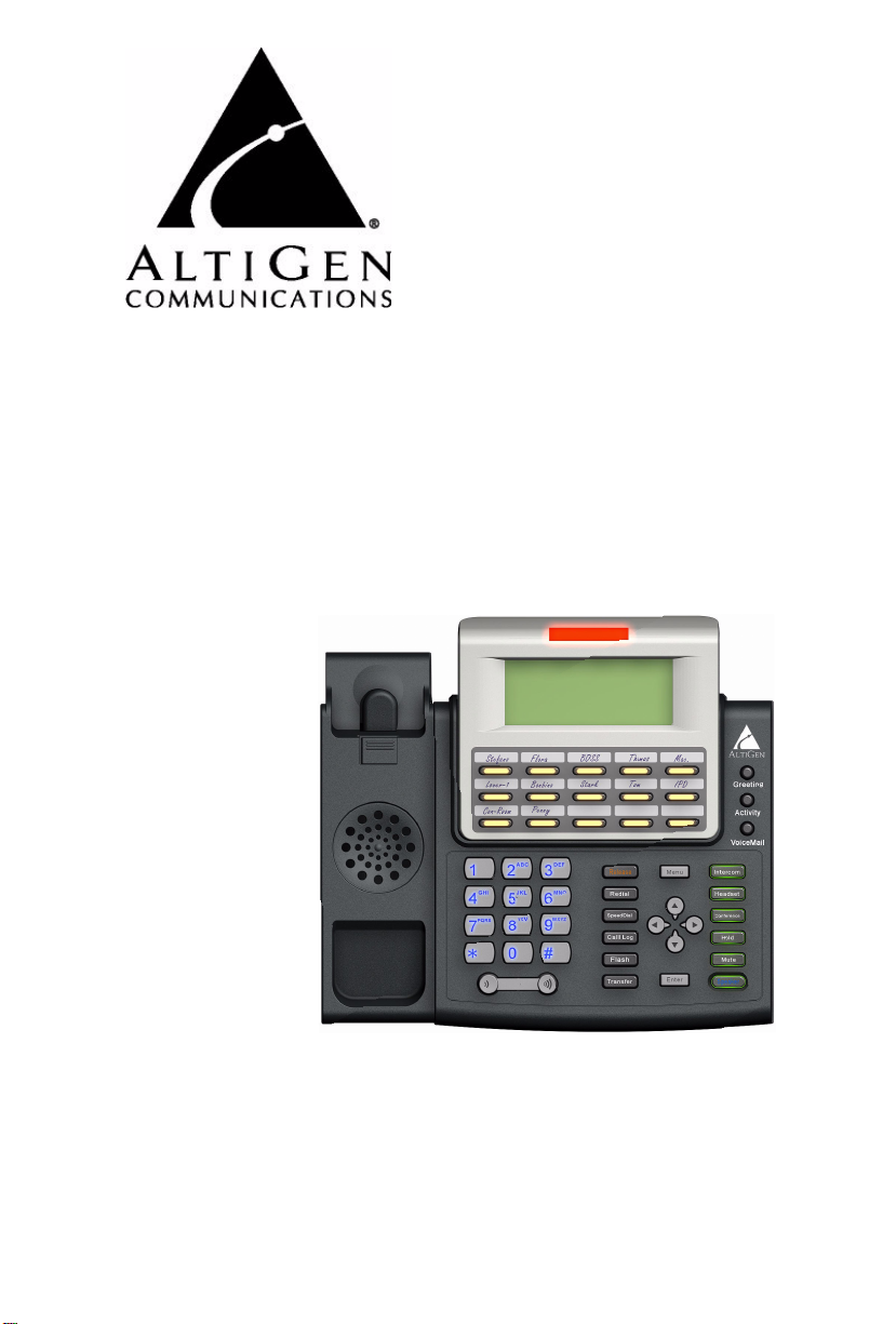
IP 720 Phone
User Manual
™
7/2009 4290-0017
Page 2

WARNING!
Toll fraud is committed when individuals unlawfully gain access to
customer telecommunication systems. This is a criminal offense.
Currently, we do not know of any telecommunications system that is
immune to this type of criminal activity. AltiGen Communications, Inc.,
will not accept liability for any damages, including long distance charges,
which result from unauthorized and/or unlawful use. Although AltiGen
Communications, Inc., has designed security features into its products, it
is your sole responsibility to use the security features and to establis h
security practices within your company, including training, security
awareness, and call auditing.
NOTICE
While every effort has been made to ensure accuracy, AltiGen
Communications, Inc., will not be liable fo r technical or edit orial errors or
omissions contained wit hin the documen tation. The i nformation contained
in this documentation is subject to change without notice.
This documentation may be used on ly in accord ance with the terms of the
AltiGen Communications, Inc., License Agreement.
AltiGen Communications, Inc.
410 East Plumeria Dr.
San Jose, CA 95134
Telephone: 888-AltiGen (258-4436)
Fax: 408-597-9020
E-mail: [email protected]
Web site: www.altigen.com
TRADEMARKS
MAX Communication Server, MaxAdministrator, MaxCommunicator,
MaxAgent, MaxSupervisor, MaxInSight, MaxOutlook, MaxCall,
Enterprise Manager, AltiServ, AltiLink, AltiConsole, VRPlayer,
Zoomerang, IPTalk, Alti-Mobile Extension, InTouch Dialer, AltiReport,
and SuperQ are trademarks or registered trademarks of AltiGen
Communications, Inc.
All other brand names mentioned are trademarks or registered tr ademar ks
of their respective manufacturers.
Copyright © AltiGen Communications, Inc., 2009. All rights reserved.
Part Number 4290-0017
Page 3

Contents
Contents . . . . . . . . . . . . . . . . . . . . . . . . . . . . . . . . . . . . . . . . . . . i
Warranty . . . . . . . . . . . . . . . . . . . . . . . . . . . . . . . . . . . . . . . . . .v
About This Manual . . . . . . . . . . . . . . . . . . . . . . . . . . . . . . . . . .1
CHAPTER 1
The IP 720 Phone . . . . . . . . . . . . . . . . . . . . . . . . . . . . . . . . . . .3
Hardware Items in the Package . . . . . . . . . . . . . . . . . . . . . . . . . . . . 7
Supported Telephony Features . . . . . . . . . . . . . . . . . . . . . . . . . . . . . 7
American Disabilities Act (ADA) Compliance . . . . . . . . . . . . . . . 11
CHAPTER 2
Setting Up the IP 720 Phone . . . . . . . . . . . . . . . . . . . . . . . . .13
Miscellaneous Operation Notes . . . . . . . . . . . . . . . . . . . . . . . . . . . 15
CHAPTER 3
Configuring the IP 720 Phone . . . . . . . . . . . . . . . . . . . . . . . .17
Phone Settings . . . . . . . . . . . . . . . . . . . . . . . . . . . . . . . . . . . . . . . . 17
System Settings . . . . . . . . . . . . . . . . . . . . . . . . . . . . . . . . . . . . . . . 18
Network Settings . . . . . . . . . . . . . . . . . . . . . . . . . . . . . . . . . . . . . . 19
Registration from the Phone’s Menu . . . . . . . . . . . . . . . . . . . . . . . 19
Configuring IP Settings . . . . . . . . . . . . . . . . . . . . . . . . . . . . . . . . . 20
Assigning a Local IP Address. . . . . . . . . . . . . . . . . . . . . . . . . . . 20
Assigning a TFTP Server . . . . . . . . . . . . . . . . . . . . . . . . . . . . . . 20
Updating Phone Firmware . . . . . . . . . . . . . . . . . . . . . . . . . . . . . . . 20
Setting Ring Tones . . . . . . . . . . . . . . . . . . . . . . . . . . . . . . . . . . . . . 21
Distinctive Ringing Support . . . . . . . . . . . . . . . . . . . . . . . . . 22
Workgroup Status Display . . . . . . . . . . . . . . . . . . . . . . . . . . . . . . . 22
Greeting Button . . . . . . . . . . . . . . . . . . . . . . . . . . . . . . . . . . . . . . . 22
Activity Button . . . . . . . . . . . . . . . . . . . . . . . . . . . . . . . . . . . . . . . . 23
IP 720 User Manual i
Page 4

CHAPTER 4
User Guide . . . . . . . . . . . . . . . . . . . . . . . . . . . . . . . . . . . . . . . .25
The LCD Screen . . . . . . . . . . . . . . . . . . . . . . . . . . . . . . . . . . . . . . 25
Basic Phone Operation . . . . . . . . . . . . . . . . . . . . . . . . . . . . . . . . . 26
Appendix A . . . . . . . . . . . . . . . . . . . . . . . . . . . . . . . . . . . . . . .33
Specifications . . . . . . . . . . . . . . . . . . . . . . . . . . . . . . . . . . . . . . . . . 33
Troubleshooting . . . . . . . . . . . . . . . . . . . . . . . . . . . . . . . . . . . . . . . 34
LCD Messages . . . . . . . . . . . . . . . . . . . . . . . . . . . . . . . . . . . . . . . . 37
Local Menu Configuration Messages . . . . . . . . . . . . . . . . . . . . 37
IP Phone Running Messages . . . . . . . . . . . . . . . . . . . . . . . . . . . 38
IP Phone Boot Messages . . . . . . . . . . . . . . . . . . . . . . . . . . . . . . 39
Glossary . . . . . . . . . . . . . . . . . . . . . . . . . . . . . . . . . . . . . . . . . .41
Index . . . . . . . . . . . . . . . . . . . . . . . . . . . . . . . . . . . . . . . . . . . . .47
ii IP 720 User Manual
Page 5

NOTE
This equipment has been tested and found to comply with the limits for a
Class B digital device, pursuant to Part 15 of the FCC Rules. These limits
are designed to provid e reason able p rotection against harmf ul interference
in a residential installation. This equipmen t generates, uses and can radiate
radio frequency energy and, if not installed and used in accordance with the
instructions, may cause harmful interference to radio communications.
However, there is no guarantee that interference will not occur in a
particular installation. If this equipment does cause harmful interference to
radio or television reception, which can be determined by turning the
equipment off and on, the user is encouraged to try to correct the
interference by one or more of the following measures:
• Reorient or relocate the receiving antenna.
• Increase the separation between the equipment and receiver.
• Connect the equipment into an outlet on a circuit different from that to
which the receiver is connected.
• Consult the dealer or an experienced radio/TV technician for help.
Changes or modifications not express ly approved by the party res ponsib le
for compliance could void the user’s authority to operate the equipment.
IP 720 User Manual iii
Page 6

iv IP 720 User Manual
Page 7

Warranty
What The Warranty Covers
AltiGen Communications warrants its hardware products to be free from defects in
material and workmanship during the warranty period. If a product proves to be
defective in material or workmanship during the warranty period, AltiGen
Communications will, at it s sole op tion, repa ir, refund or repl ace the prod uct with a
like product.
How Long the Warranty Is Effective
All AltiGen Communications products are warranted for one year for all parts fro m
the date of the fir s t end user purchase.
Whom the Warranty Protects
This warranty is valid only for the first end user purchaser.
What the Warranty Does Not Cover
1. Any product on whic h the serial number has been defaced, modified or
removed.
2. Damage, deterioration or malfunction resulting from:
a) Accident, misuse, neglect, fire, water, lightning, or other acts of nature,
unauthorized product modification, or failure to f ollow instructions
supplied with the product.
b) Repair or attempte d repair by anyo n e not autho rized by AltiGen
Communications.
c) Any damage of the pr oduct due to shipment.
d) Removal or installation of the product.
e) Causes external to the product, su ch as electric power fluctuations or
failure.
f) Use of supplies or parts not meeting AltiGen Communications’
specifications.
g) Normal wear and tear.
h) Any other cause which does not relate to a product defect.
3. Shipping, installation, set-up and removal service charges.
IP 720 User Manual v
Page 8

How to Obtain Service
End user customers should contact your Authorized AltiGen Dealer for service.
Authorized AltiGen Dealers must follow the steps below for service:
1. Take or ship the product (ship ment pr epaid) to your AltiGen distribu tor or to
AltiGen Communications, Inc.
All materials being returned to AltiGen must have an associated RMA number. RMA numbers are issued by AltiGen Customer Service and can be
obtained by calling 1-888-ALTIGEN (258-4436) or submit an online RMA
request via the AltiGen Partner Resource Center, at https://dealer.altigen.com. AltiGen reserves the right to refuse return of any material that does
not have an RMA number. The RMA number should be clearly marked on
the outside of the box in which the material is being returned. For example:
Attn.: RMA # 123
AltiGen Communications, Inc.
410 East Plumeria Drive
San Jose, CA
Upon authorization of return, AltiGen will decide whether the malfunctioning product will be repaired or replaced.
2. To obtain warranty service, you will be required to provide:
a) The date and proof of pu r ch a s e
b) Serial number of the product
c) Your name an d co m pa ny name
d) Your shipping address
e) A description of the problem.
3. For additional information conta ct your AltiGen Deale r or AltiGen
Communications, Inc.
95134
Effect of State Law
This warranty gives you specific legal rights, and you may also have other rights
which vary from state to state. Some states do not allow limitations on implied
warranties and/or do not allow the exclusion of incidental or consequential
damages, so the above limitations and exclusions may not apply to you.
Sales Outside the U.S.A.
For AltiGen Communications products sold outside of the U.S.A., contact your
AltiGen Communications dealer for warranty information and services.
vi IP 720 User Manual
Page 9

About This Manual
This manual describes how to get the Alti-IP 720 phone up and running on
a voice over IP (VoIP) network.
It provides information about how to set up, connect cables to, and
configure an IP 720 phone. It also provides information on how to
configure the network and IP settings.
How to use the phone is described in Chapter 4.
Related Documentation
• IP 720 Quick Reference Card covers basic end user phone features,
configuration from the IP phone, and AltiServ feature codes.
•The MAX Communication Server Administration Manual provides
detailed information on configuring AltiGen IP phone s in
MaxAdministrator.
IP 720 User Manual 1
Page 10

2 IP 720 User Manual
Page 11
C
1
4 - 6
7 - 12
13 - 15
16 - 21
22
3
2
HAPTER
1
The IP 720 Phone
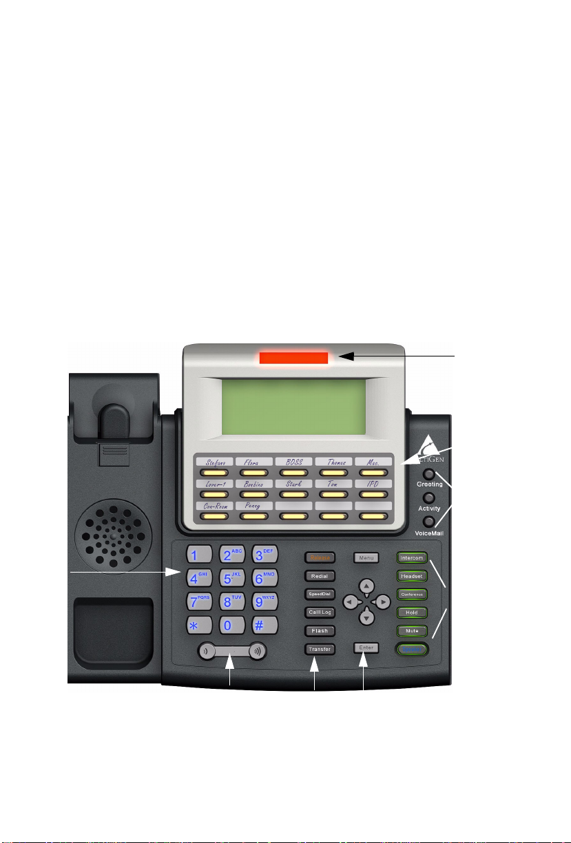
TheAltiGen IP 720 phone is a business telephone that provides voice
communication over an IP network.
The IP 720 provides built-in power-over-Ethernet support and functionality
similar to traditional business phones, including automatic redial, on-hook
dialing, hands-free operation, 15 programmable keys, LCD display, and
headset port support for the Plantronics wireless headset.
The main components of the phone are illustrated in the figures below and
described in the table that follows each figure.
23
Figure 1. IP 720 Phone
IP 720 User Manual 3
Page 12

1 LCD Screen Displays features such as date, time, phone number,
caller ID, call waiting, line/call status and call time.
2 Message
Waiting
Indicator
Light*
3 Program-
mable Keys*
1-15
4 Greeting* Greeting access button.
5 Activity* Activity code access button.
6 VoiceMail* Voice mail access button.
7 Intercom* Incoming voice path through speaker, indicated by
8 Headset Hook switch for headset device.
9 Conference* Initiates a conference call, indicated by the button’s
Blinks when a message is waiting or a c all is coming
in.
15 programmable keys can be configured by the
system administrator in MaxAdministrator as a
Busy Lamp Field (BLF) key, an AltiServ Feature
Code key, an Admin Defined # key, a Line Park
key, a Call Record key, a Workgroup Stat us key,
or a User Defined # key.
the button’s blinking light.
blinking light.
10 Hold* Places a call on hold, indicated by the button’s
blinking light.
11 Mute Engages or disengages mute function.
12 Speaker Enables speaker.
13 Menu Displays the phone’s menu.
4 IP 720 User Manual
Page 13

14 Navigation
buttons
15 Enter Confirms selections made in the LCD, including
16 Release Releases a call, exits from the menu, releases phone
17 Redial* Redials up to last 16 calls and up to 32 digits.
18 SpeedDial* Displays a li s t of Station Speed Dial entries
19 Call Log* Displays the caller IDs of up to 99 incoming calls.
20 Flash* For system feature codes that need a fl ash to
/buttons let you scroll t hrough tex t on the LCD
screen.
button selects a menu item or setting.
button returns to previous configuration menu or
deletes the last digit input.
settings.
from an active state.
configured th rough MaxCommunicator/MaxAgent
or MaxAdministrator. To mak e an outgoing call, u se
the / buttons to select a Speed Dial entry, then
press Enter.
To dial, use the / buttons to select a call lo g
entry, then press Enter.
complete.
21 Transfer* Transfers a call.
22 Volume Adjusts volume of ringer , speaker, handset and
headset.
23 Dial Pad Functions like a dial pad on a traditional telephone
and is also used for inputting some settings that are
accessed through the phone’s menu.
Note: * Indicates a normal operating mode key feature, which is
available only after registering the IP 720 with the phone server
and logged in as an extension.
IP 720 User Manual 5
Page 14
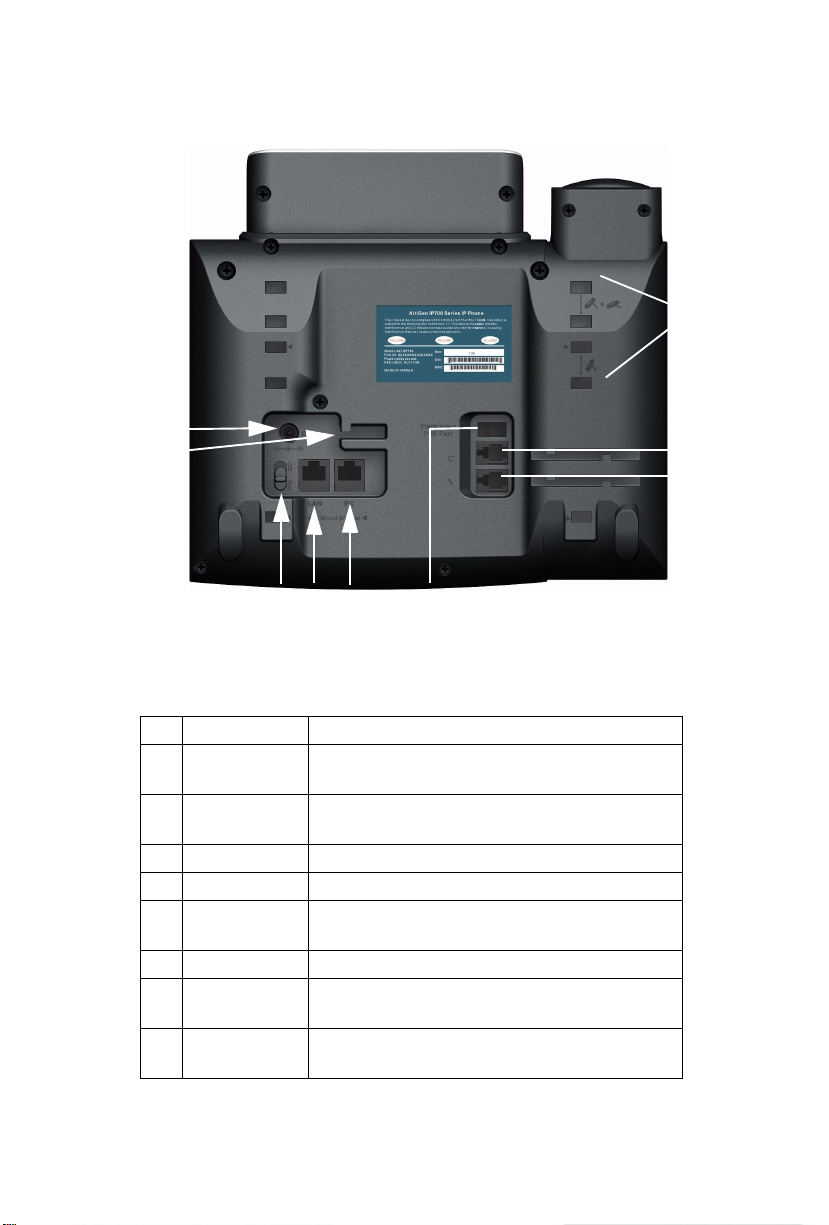
Figure 2. IP 720 Phone, Bottom View
5
4
3
1
9
2
6
8
7
1 DC Port Connects to power outlet
2 Power Cable
Restraint
3 DC/PoE Switch Switches between DC power and Power over
4 LAN Port Connects to network ( 10/100/1000 Base T)
5 PC Access Port Connects to PC (10/100/1000 Base T)
6 Plantronics
PSB Port
7 Handset Port Connects to a handset
8 Headset Port Connects to a non-amplified headset with RJ9
9 Slots for the
Phone Stand
Secures the power cable, preventing it from
accidentally being pulled out
Ethernet
(Plantronics serial bus port) Connects to a
Plantronics wireless headset base
connector
Four slots on each side for inserting the phone
stand to set the phone at the desired angle
6 IP 720 User Manual
Page 15

Hardware Items in the Package
The following hardware items are included in this package:
• IP 720 set and stand
• Handset
• Handset cord
• Power cord
• Network cable
• 3.5 mm to USB cable
You can purchase separately:
• A wall mount bracket
• AC/DC power adapter
Supported Telephony Features
The IP 720 provides a broad range of call handling and dialing features
directly on the phone and through the MAX Communication Server
system. The following table lists the supported features, a brief description
of each, and configuration and use notes where applicable.
Feature Description Notes
Activity
button
Auto Answer When a call comes in, the
Lets users se t an activity
code that specifies their
activity status (for
example, in a meeting)
when they are not at the
phone.
IP phone will ring for a
specified number of
seconds, connect the call,
and automatically answer
through the speaker or
headset.
• Callers in the system are notified
of the activi ty status wh en a call is
not answered.
• During ringing, the user can
manually pick up the call from
headset, handset or speaker.
IP 720 User Manual 7
Page 16

Auto Answer
Ring
When Auto Answer is set
to Yes, specifies how
many seconds the IP
phone should ring before
the call is automatical ly
answered (1-20 seconds).
Auto Answer
Dev [device]
Busy Lamp
Field (BLF)
When Auto Answer is set
to Yes, specifies whether
the call should be
automatica lly answered
through the speaker or
headset.
Associates a
programmable key w it h
an extension that ca n be
automatically di aled when
selected; the key’s light
indicates that the
extension is busy and
blinks when ringing.
The BLF ring tone is
played only when the
phone is in idle state. It is
stopped when the
destination phone st ops
ringing or the local phone
exits idle state.
When multiple BLF
extensions ring
simultaneously, the IP
phone will play the first
BLF extension ringer and
beep tones and ignore
other BLF extensions.
• Must be configured by the system
administrator.
• The BLF fe at ure ca n be assigned
only to internal extension
numbers, no t outside number s .
• The feature is not available in
BASIC mode.
Call Log Shows the history of
incoming calls, up to 99.
8 IP 720 User Manual
• Pressing the Enter button will
dial the number displayed. If 20
seconds pass without any input,
the phone exits the Call Log.
Page 17

Call Record Allows a programmable
key to be used for ondemand recording.
• Must be enabled by the system
administrator.
• User presses the key to start
recording, presses the key aga in to
stop recording. There is no pause
function. When the ca ll is
recording, the light is on.
• Recorded conversations can then
be played back through voice mail
or accessed at a centralized
location.
Conference
button
Workgroup
Status
Flash button Si gna ls PBX tha t special
Greeting
button
Initiates a conference and
adds in other parties one at
a time.
Displays the workgroup
status in the LCD.
instructio n s will follow.
Lets user recor d greet ings
and select a greeti n g to
play.
• Single Call Waiting, Multiple
Call Waiting or Live Call
Waiting must be enabled for the
extension by the system
administrator or in
MaxCommunicator/MaxAgent in
order to add incoming calls t o a
conference.
• The user who initiates the
conference call can select another
conference member’s call and drop
it from the conference by
disconnecting the ca ll . The f eatu re
is unavailable to all other
conference members, even wh en
the conference initiator hangs up.
• The system administrator
configures which key will displa y
the workgroup status.
• Greetings are affiliated with
activity codes.
IP 720 User Manual 9
Page 18

Headset
button
When pressed, the user
will be able to activate the
RJ-9 headset port.
• This button is used as a hook
switch for headset ports.
• The button is used as a headset-in-
use indicator whe n a Pl an tronics
wireless PSB port is connected.
The headset on-hook and off-hook
is controlled by the Plantronics
headset mo d ule.
Hold button Places an active call on
Intercom
button
Line Park A pa rked call line
hold.
Connects you directly to
the callee’s intercom after
one ring.
appearance ca n be
assigned as a
programmable Line Park
key by the administrator.
When connected to a
caller, the call ca n be
parked by pressing the
Line Park key. If a call is
parked at a Line Park li ne,
the button’s light is on.
The call can be picked up
by pressing the Line Park
key.
• When Multiple Call Waiting is
enabled at the extension, the user
can put multiple incoming calls on
hold and retrieve using the phone’s
/ buttons and Enter button.
• Pressing Hold while onh ook will
retrieve the last hold call.
• Supports up to 9 hol d ca lls.
• When configured by the system
administrator, the IP ph one ca n
play an audible beep or one of 14
different ring tones when a ca l l is
parked.
• When configured by the
administrator, an alternate way to
pick up a parked call is to use #51
<line number> if Line Par k is not
assigned to a programmab le key.
• The Line Park key’s light will be
lit and turns off when t h e par k ed
call is picked up, the caller hangs
up, or the call is routed to IVR/
Auto Attendant.
Mute button While on a call, mutes
Program
Keys
conversation.
Lets users associate a
programmable key with a
speed dial number or
feature code directly from
the IP phone.
10 IP 720 User Manual
• If the system administrator has
allowed it, you can asso ci ate
certain programmable keys w i th a
speed dial number or feature code
from the IP phone menu.
Page 19

Redial button Redials a s elected number
from the last16 numbers
dialed.
• Pressing Enter dials the number
displayed.
• Redials up to 32 digits.
• When a new call comes in, the
phone will exit this menu and go to
ring state. If in this menu for longer
than 20 seconds without any input,
the phone exits this menu.
Release
button
Ring Tones Select from one of 14 ring
Speaker
button
Speed Dial
button
Transfer
button
Voice Mail
button
Releases a call from the
connected state. Deletes
characters entered on the
LCD. While onhoo k,
releases phone from an
active state.
tones.
Enables use of speaker
phone.
Quickly dials a selected
number from a list that has
been previously stored.
Transfers an active call to
another number.
Enables acce s s to voice
messages.
• Custom ring tones are not
supported.
• These are speed dial numbers
configured by the system
administrator.
• This button cannot be used to
“flash” after bei ng used to tran sfer
a call. To reconnect to a call after
using the Transfer button, use
thebutton or th e Flash button.
• The VM count that appears in the
LCD reflects new messages
(previously heard messages are not
included).
American Disabilities Act (ADA) Compliance
The hearing aid-compatible handset on the IP 720 phone is equipped with
a magnetic coupler, which meets the ADA HAC requirements.
The dialing pad also complies with ADA standards.
IP 720 User Manual 11
Page 20

12 IP 720 User Manual
Page 21

C
HAPTER
Setting Up the IP 720 Phone
To set up the IP 720 phone, follow these instructions:
1. Gather network settings information (this information is needed to
configure the IP 720):
• MAX Communication Server (MAXCS) IP address
• IP 720 phone’s IP address
This address is needed if your company does not use Dynamic Host
Configuration Protocol (DHCP), which automatically assigns IP
addresses to devices when they are connected to the network. The
phone’s IP address can be obtained from your sy stem administrator.
2. Connect the IP 720:
a. Connect the handset to the handset port.
b. On the underside o f the phone, mov e the DC - Po E switch to PoE.
2
Or, if using DC power (and you have an AC/DC power adapt er),
move the switch to DC, connect the power plug to the DC port,
and plug in the phone.
c. Connect the phone to the LAN that MAXCS is on.
d. Once the phone is activated, connect an Ethernet cable from
another network device, such as a desktop computer, to the PC
access port on the phone.
3. After the IP 720 has power connected to it, the phone begins its
automatic booting process by cycling through these steps:
• All LED lights will be on.
• The LCD screen displays [ATGN BOOT] on the first line.
• On the second line of the LCD screen, th e f ollowing mess ages are
displayed in succession:
IP 720 User Manual 13
Page 22

—CHECK MEMORY (RAM checking state)
—CHECK FW (Firmware checking state)
—INIT NETWORK
—LOADING FW...
—LOADING NOW.
—Boot Done
—INITIALIZING
4. Configure startup network settings. (To displ ay the phone’s menu, as
required below, press the Menu button on the phone. Use the/
buttons to scroll through the menus and settings in the LCD screen.
Press the Enter button to select a menu item or a setting.)
If you are using DHCP, ensure that DHCP is enabled on the IP 720
phone: Menu > NETWORK > ENABLE DHCP > Yes. (DHCP is
enabled by default.)
If your company does not use DHCP, disable DHCP on the IP 720
phone: Menu > NETWORK > ENABLE DHCP > No. In this case,
configure the following network settings on the IP 720 after setting up
the phone:
• Local IP address
• IP subn et mask
• Gateway IP address
5. Configure the MAXCS IP settings (see “Configuring IP Settings” on
page 20 for information about IP settings):
a. Menu > SYSTEM >Enter.
b. Select AW SERVER, and press Enter.
c. Enter the MAXCS server address, using the * key to input periods,
and press Enter.
6. Activate the IP 720 extension from the IP phone:
a. With the handset onhook, press #27, then the Enter button.
b. Enter the extension number and password when prompted.
14 IP 720 User Manual
Page 23

c. The phone will attempt to register, as shown in the LCD screen:
REGISTERING...
01/12 04:16PM x300
If the phone successfully passes through these stages, the phone
shows the date, time, and extension in the LCD screen and is now in
normal operating mode.
If it doesn’t pass through these stages successf ully, refer to
“Troubleshooting” on page 34.
Miscellaneous Operation Notes
• Logging in and out—When using #26 and #27 to log out / log in, the
IP 720 must be onhook. Pressi ng t he Speaker button and then us in g
#26 or #27 will not work.
• BASIC mo de—If the IP 720 phone fails to register with MAXCS
during startup, the phone operates in Basic mode. When in Basic
mode, the IP phone’s LCD display shows (BASIC) IDLE.
No MAXCS switching features are available in this operating mode.
However, the phone user can enter a destination IP address followed
by #, and make an outgoing call through the IP network to reach
MAXCS or another IP 720 phone. Also, the IP phone can accept
incoming calls originating from MAXCS or another IP 720 phone.
If the IP phone’s local configuration is changed while in BASIC
mode, the changes are overridden by MaxAdministrator settings.
• Incoming call takes priority—If a call comes in while you are using
any phone menu or display (such as workgroup d isplay or Cal l Log),
the phone will exit the menu and go to the ring state.
• Restoring default settings—To automatically restore the original
default settings for the IP 720 phone:
1. Press the Menu button.
2. Press * * 2, then press the Enter button.
IP 720 User Manual 15
Page 24

• Rebooting the phone—To reboot the IP 720 phone, press * * 3, then
press the Enter button.
16 IP 720 User Manual
Page 25

C
HAPTER
Configuring the IP 720 Phone
Phone, system, and network settings can be configured through the IP
phone’s menu. The phone can also be registered through this menu, if
necessary.
• To g et to the menu , press the Menu button.
• / buttons scroll the menus and settings in the LCD screen.
• button selects a menu item or a setting.
•The Enter button also selects a menu item or a setting.
• button returns to the previous menu.
•Press the Release button to exit the menu.
The following tables describe each setting and the corresponding menu
path.
Important: Your IP 720 phone should be in normal operating mode
when you configure it. If your IP phone is in BASIC mode
(shown in the LCD display), your changes will be
overwritten by MaxAdministrator settings when the phone is
successfully registered.
3
Phone Settings
Setting Menu Path Description
Extension
Number
Extension
Password
Program
Keys
Phone Setting >
Ext Number
Phone Setting >
Ext Password
Phone Setting >
Program Keys >
Program Key [#]
Sets the IP phone’s exten sion
number.
Sets the IP phone’s exten sion
password.
Sets the speed dial number or feature
code for a select ed key.
IP 720 User Manual 17
Page 26

Ring Tone Phone Setting >
Ring Tones
Sets the desired ring tone.
Auto Answer Phone Setting >
Auto Answer
Ring
Auto Answer
Device
Auto Answer
Phone Setting >
Auto Ans Ring
Phone Setting >
Auto Ans Dev
Sets whether to enable automatic
answering.
Sets how many seconds the phone
should ring before it is au tomatically
answered. Appears on menu when
Auto Answer is set to Yes.
Sets whether speaker or headset is
the automatic answering device.
Appears on menu when Auto
Answer is set to Yes.
System Settings
Setting Menu Path Description
AW Server System > AW Server Sets the MAXCS IP addres s .
Trunk
Access Code
Hour Offset System >
SYSTEM >
TRK ACCESS CODE
Hour Offset
Sets the digit required to enab le a
user to return an outside call from the
Call Log.
Sets the tim e o ffset from the
MAXCS time.
TFTP Serve r System >
Boot
Download
Emergency
Number
TFTP Server
System >
Boot Download
System >
Emergency Num
18 IP 720 User Manual
Sets the TFTP server IP address for
updating firmware.
After firmware image upgrade, this
setting changes to No. U s ed mainly
for upgrading or troubleshooting. On
the next boot, the IP phone will
download the new firmware from the
TFTP server, if set to Yes.
Sets the IP phone’s emergency
number. For the U.S., the emergency
number is 911.
Page 27

Emergency
Gateway
System >
Emergency GW
Sets the IP phone’s emergency
gateway IP address
Enable SIP
Registration
Version
Information
System >
Enable SIP
Registration
System >
Version Info
[Read only]
Enables SIP registration to the
emergency gateway
Displays the version number of the
IP phone.
Network Settings
Setting Menu Path Description
Enable DHCP Network >
Local
Address
Network
Mask
Gateway Network >
Enable DHCP
Network >
Local Address
Network >
Network Mask
Gateway
Sets whether Dynamic Host
Configuration Protocol (DHCP) is
being used by the IP phone to retrieve
a new IP address upon boot up.
Sets the IP phone’s local addres s;
shows only if DHCP is disabled.
Sets the IP phone’s network mask;
shows only if DHCP is disabled.
Sets the default Gateway IP address.
Registration from the Phone’s Menu
Under normal circumstances, the IP 720 phone registers itself
automatically. However, if registration failed for some reason (for
example, the server was not available), registration can be started again
from the IP 720 phone’s menu:
1. Press the Menu button.
2. Scroll to REGISTER.
3. Press the Enter button.
IP 720 User Manual 19
Page 28

Configuring IP Settings
An IP address is a unique logical address that identifies each host computer
on a TCP/IP network. An IP address is a 32-bit number expressed as four
decimal numbers from 0 to 255, separated by periods.
Use these guidelines when manually configuring the IP settings:
• Ensure the default gateway IP address is on the same subnet as the host
IP address. Check with your system administrator.
• When inputting IP address es into the IP 720, use the * key to enter
periods. For example, 209.120 .12. 8 would be inp ut as 209*12 0*12* 8.
Assigning a Local IP Address
To assign an IP address, use the following steps:
1. Ensure that DHCP is disabled.
2. Press the Menu button, scroll to NETWORK, then press the Enter
button.
3. Scroll to LOCAL ADDRESS, and press Enter.
4. Use the keys on the dial pad to enter a new IP addr ess, using the * key
to enter periods.
5. Press Enter.
Assigning a TFTP Server
The default TFTP Server is set to 0.0.0.0.
To assign the TFTP server, use the following steps:
1. Press the Menu button.
2. Use / to select System, th en pr ess th e Enter button.
3. Scroll to TFTP Server, and press Enter.
4. Use the keys on the dial pad to enter the new TFTP server address,
using the * key to enter periods, then pr ess Enter.
Updating Phone Firmware
To update the phone firmware directly from the IP 720 phone, follow these
steps:
20 IP 720 User Manual
Page 29

1. Press the Menu button.
2. Use the button to scroll to System, then press the Enter button.
3. Scroll to TFTP Server, then press Enter.
4. Enter the TFTP server address, using the * key to input periods.
5. The IP 720 will download the firmware from the TFTP server on the
next reboot.
6. Reboot by unplugging and replugging the power cable OR by
pressing * * 3 and the Enter button.
7. Once the IP phone is rebooted, all LED lights come on for a brief
time.
8. The LCD screen displays [BOOTING] on the first line.
9. On the second line of the LCD screen, the following messages are
displayed in succession:
—CHECK MEMORY (RAM checking state)
—CHECK FW (Firmware checking state)
—INIT NETWORK
—LOADING FW...
—LOADING NOW.
—Boot Done
—INITIALIZING
10. You may verify the new version of firmwar e: Press the Menu button,
scroll to SYSTEM and press Enter, scroll to Version Info and
press Enter.
Setting Ring Tones
The IP 720 phone has 14 ring tones available. To set the ring tone:
1. Press the Menu button.
2. Select PHONE SETTING, then press the Enter button.
3. Scroll to RING TONES and press Enter.
4. Scroll to the desired ring tone and press Enter.
Note: Custom ring tones are not supporte d.
IP 720 User Manual 21
Page 30

Distinctive Ringing Support
WG200 CIQ05 LQT05
LOGIN >TH02 SL060
Not Ready
If the Distinctive Ring options are enabled by the system administrator,
you may have three different ring cadences that distinguish the types of
calls:
• Internal call = 1 ring
• External call = 2 rings
• Operator call = 3 rings
Workgroup Status Display
A programmable key can be configured in MaxAdministrator to display
workgroup status when the key is press ed. The workgroup status display is
in the following format:
WG - workgroup number (up to 4 digits)
CIQ - number of calls currently in the queue
LQT - longest queue time of current queued calls
LOGIN - LOGIN/LOGOUT indicates the agent login/logout state
TH - number of calls in the queue whose queue time is greater than the
service level threshold
SL - service level in percentage
Not Ready - the agent is not ready to receive workgroup calls
Greeting Button
The IP 720 phone’s Greeting button is a shortcut to the greeting feature in
voice mail. It lets users:
• Record a greeting
• Enter a directory name
• Select which greeting to use
22 IP 720 User Manual
Page 31

Greetings are affiliated with activity codes. The user can choose, for
example, the “meeting” greeting or the “business travel” greeting. See
“Activity Button,” below.
Activity Button
The IP 720 phone’s Activity button lets users select an activity code that
corresponds to their activity status (for example, at a meeting or in
training). The selected code appears in the upper right of the LCD screen.
When an IP 720 user calls an extension in the system that has activity codes
set up and the call goes into RNA handling, or the destination user has DND
enabled, the activity code is displayed on the IP phone.
Note: Called party activity display is not available in Basic mode. Also,
the activity displayed on the IP phone may truncate the caller ID/
caller name.
The administrator can change the activity codes in MaxAdministrator in the
System Configuration dialog box, Activity tab.
To select an activity code from the IP 720 phone:
1. Press the Activity button.
2. Press / to scroll through the codes.
3. Press Enter to select a code.
IP 720 User Manual 23
Page 32

24 IP 720 User Manual
Page 33

C
01/12 04:16PM x555
DND MISSED xx 3VM
WG200 CIQ05 LQT05
LOGIN >TH02 SL060
Not Ready
HAPTER
4
User Guide
The LCD Screen
In normal operating mode, the phone’ s LCD screen displays the date, time,
and extension number on the first line:
If an activity code has been set on the phone, that code is displayed in place
of the extension number. Examples of activity codes are MEETING,
AWAY, TRAVEL.
Other messages you may see:
DND or FWD - The extension has Do Not Disturb on or is set to forward
all calls.
MISSED xx - Number of calls missed.
VM - Indicates the number of new voice m essages.
Workgroup Status Display
When the system administrator has configured a programmable key to
display workgroup status when pressed, the workgroup status display is in
the following format:
WG - Workgroup number.
CIQ - Number of calls currently in the queue.
LQT - Longest queue time of current queued calls.
LOGIN - LOGIN/LOGOUT indicates the agent login/logout state.
IP 720 User Manual 25
Page 34

TH - Number of calls in queu e whose queue time is greater than the service
level threshold.
SL - Service level in percentage.
Not Ready - Agent is not ready to receive workgroup calls.
Basic Phone Operation
* Indicates a normal operating mode phone feature, which is available only after
registering the IP 72 0 with the phone server and l ogging in as an extension.
FUNCTION KEY SEQUENCE
Activity 1) Press the Activity button.
2) Use the / buttons to select the appropriate activity, and
press the Enter button.
Callers in the system are notified of the activity status when a
call is not answered.
Auto Answer 1) Press the Menu button, select PHONE SETTING, then
Call Log* 1) With the phone onhook, press the Call Log button.
select AUTO ANSWER.
2) Use the / buttons to enable/disable Auto Answer mode,
and press Enter.
3) Select AUTO ANS RING from the menu.
4) Set the number of seconds to ring before auto answer (1-20),
and press Enter.
5) Select AUTO ANS DEV from the menu, then select from
speaker or headset as the Auto Answer device, and press
Enter.
2) Use the / buttons to scroll to the number you want.
3) Press the Enter button to dial the number.
The Call Log stores up to 99 incoming numbers.
26 IP 720 User Manual
Page 35

Conference* To initiate a conference during a call:
1) Press the Conference button (this automatically selects a
new line and places the other party on hold).
2) Enter the target telephone number.
3) When the call connects, press the Conference button again
OR the button to cancel the conference and return to the
original party.
The number of parties allowed in a conference call depends on
the AltiServ system. In general, up to 6 parties are allowed.
To conference an incoming call when no conference is in
progress:
1) Connect to a caller.
2) Get incoming call whose Caller ID or Caller Name is
displayed on the LCD. Call waiting tone is played.
3) Press the Enter button to answer caller and place the
original caller on hold.
4) Press the Enter button to select the original hold call.
5) Press the Conference button to create a conference and join
both callers.
If a conference is already in progress, to conference an
incoming call:
1) Press the Enter button to answer the incoming call (all other
conference members remain in conference).
2) Press the Enter button and select one of the members in
conference (displays “ConfHold”), then press the
Conference button to join the incoming caller to the
conference.
The user who initiates the conference call can select another
conference member’s call and drop it from the conference.
To drop a conference member:
1) Use the / buttons to select the member to disconnect.
2) Press the button to disconnect this caller.
• This feature is not available to other conference
members, even when the conference initiator hangs up.
Configuration
Menu
• Press the Menu button to display the phone menu.
• Use the / buttons to scroll to the menu item you want.
• Use thebutton or Enter button to select a menu item or
setting.
• Use thebutton to return to the previous menu.
IP 720 User Manual 27
Page 36

Greeting* Press the Greeting button to quickly access voice mail
Handset/
Headset/
Speaker
Hold* During a call:
Intercom* Incoming Intercom:
Line Park* During a call:
Mute While on a call with speaker, handset, or headset on:
greetings.
To switch between handset, headset and speaker, the user can
go offhook, press the Speaker button, or press the Headset
button.
1) Press the Hold button to put the current call on hold and
make a new call.
To retrieve a single call on hold:
1) Press the Hold button.
To retrieve multiple calls on hold:
1) Use / to select a hold call to be retrieved.
2) Press the Enter button.
OR
1) Press the Hold button to retrieve the last hold call.
Incoming voice path is heard through the speaker, indicated by
the button’s blinking indicator light.
Outgoing Intercom:
1) Press the Intercom button, then the extension number.
1) Press #51 and then enter the 2-digit Line Park line.
OR, press the Line Park key (if the administrator has
configured one). The Line Park key’s light will be lit and
turns off when the parked call is picked up, the caller hangs
up, or the call is routed to voice mail.
1) Press the Mute button.
2) To disengage mute, press the Mute button again.
28 IP 720 User Manual
Page 37

Programmable Key*
• N/A
• BLF
• Feature
Code
• Admin
Defined #
• Line Park
• Call
Record
• Workgroup
Status
• User
Defined #
Reboot 1) Press * * 3, then the Enter button
Redial Phone is onhook
1) Press the appropriate key (keys 1-15) to initiate one of the
following functions pre-assigned by the system
administrator: Busy Lamp Field, AltiServ Feature Code,
Admin Defined #, Line Park, Call Record, Workgroup Status,
User Defined #.
To configure a programmable key with User Defined #
enabled:
a. Press the Menu button, select PHONE SETTING, and
press the Enter button.
b. Scroll to PROGRAM KEYS and press Enter.
c. Select the key to program, and press Enter.
d. Enter the appropriate digits for the speed dial number or
feature code, and press Enter.
The digits are automatically dialed when this function key is
pressed.
1) Press the Redial button.
2) Use / to scroll to the desired entry. ( scrolls to previous
entry, scrolls to fi r st entry.)
3) Press the Speaker button or raise handset.
• Redial up to last 16 calls.
• Redial up to 32 digits.
Release For a connected call:
1) Press the Release button to hang up the call.
Also, press the Release button to exit the menu.
Restore
Default
Settings
Ring Tones 1) Press the Menu button.
Speaker To use the speakerphone:
1) Press the Menu button.
2) Press * * 2, then the Enter button.
2) Select PHONE SETTING, and scroll to RING TONES.
3) Select a ring tone and press the Enter button.
Note: Custom ring tones are not supported.
1) Press the Speaker button.
2) To disconnect the call, press the Speaker button again.
IP 720 User Manual 29
Page 38

Speed Dial* 1) Press the Speed Dial button to see a list of phone numbers
Transfer* During a call:
Voice Mail 1) Press the Voice Mail button.
configured by the system administrator.
2) Use / to scroll to the desired entry.
3) Press the Enter button to dial the number.
1) Press the Transfer button, which places the call on hold.
2) Dial the number you want to transfer the call to.
3) Hang up if the party answers the call, or press Transfer
again to co mplete tran s ferring.
4) If the party refuses the call, return to the original call by
pressing the button or the Flash button.
2) Enter voice mail password.
• The Message Waiting light blinks when a voice mail
message is waiting.
• The LCD displays the new voice mail count (which includes
only unheard messages) when onhook.
Volume To adjust volume on handset/speakerphone/headset:
1) Depending on which volume you want to adjust, take the
phone offhook by lifting the handset, pressing the Speaker
button, or pressing the Headset button.
2) Press the Volume button. The device name and volume
level appear in the LCD.
3) Press the left side of the Volume button to decrease the
volume; press the right side to increase the volume.
To adjust ringer volume:
1) Leave the phone onhook.
2) Press the Volume button; a sample ring plays and the
volume level appears in the LCD.
3) Press the left side of the Volume button to decrease the
volume; press the right side to increase the volume.
* * Feature Codes
* * 2 . . . . . . . . . . . . . . . . . . . . . . . . . . . Restore default settings (when user is in the
* * 3 . . . . . . . . . . . . . . . . . . . . . . . . . . . Reboot
Configuration Menu)
AltiServ Feature Codes
## <pwd>. . . . . . . . . . . . . . . . . . . . . . . Log in to voice mail at your own station
### <ext> <pwd>. . . . . . . . . . . . . . . . . Log in to voice mail at another station
AltiGen Voice Mail System Quick Features
#11 . . . . . . . . . . . . . . . . . . . . . . . . . . . Greeting Menu
#28 . . . . . . . . . . . . . . . . . . . . . . . . . . . Password Menu
30 IP 720 User Manual
Page 39

Making Calls
#34. . . . . . . . . . . . . . . . . . . . . . . . . . . . Dial By Name
1
#35. . . . . . . . . . . . . . . . . . . . . . . . . . . . Virtual Log In (Station Privilege Override)
#69. . . . . . . . . . . . . . . . . . . . . . . . . . . . Dial Last Caller
#77. . . . . . . . . . . . . . . . . . . . . . . . . . . . Station Speed Dial
#88. . . . . . . . . . . . . . . . . . . . . . . . . . . . System Speed Dial
#99. . . . . . . . . . . . . . . . . . . . . . . . . . . . Last Number Redial
#93 <ext>. . . . . . . . . . . . . . . . . . . . . . . Intercom Call
2
Answering Calls
#29 <ext>. . . . . . . . . . . . . . . . . . . . . . . Individual Call Pickup (a specific station)
#30. . . . . . . . . . . . . . . . . . . . . . . . . . . . System Call Pickup (any station ringing)
Flash button #31 . . . . . . . . . . . . . . . . . Personal Call Park
#31 <ext>. . . . . . . . . . . . . . . . . . . . . . . Personal Call Park Pickup
Flash button #41 . . . . . . . . . . . . . . . . . System Call Park
#41 <loc. #>. . . . . . . . . . . . . . . . . . . . . System Call Park Pickup
#51 <line park line> . . . . . . . . . . . . . . . Line Park Pickup
#81. . . . . . . . . . . . . . . . . . . . . . . . . . . . Hands Free Intercom Mode
#82. . . . . . . . . . . . . . . . . . . . . . . . . . . . Hands Free Manual Answer Mode
Call Management
#26. . . . . . . . . . . . . . . . . . . . . . . . . . . . Station Log Out (Phone must be onhook)
#27. . . . . . . . . . . . . . . . . . . . . . . . . . . . Station Log In (Phone must be onhook)
#32 <acct code> . . . . . . . . . . . . . . . . . Enter Account Code (before dialing)
Flash button #32 <acct code>. . . . . . . Enter Account Code (mid-call)
#33. . . . . . . . . . . . . . . . . . . . . . . . . . . . Do Not Disturb
#36. . . . . . . . . . . . . . . . . . . . . . . . . . . . Call Forwarding
#37. . . . . . . . . . . . . . . . . . . . . . . . . . . . Remote Call Forwarding
Other Features
#12. . . . . . . . . . . . . . . . . . . . . . . . . . . . Language Selection
#14. . . . . . . . . . . . . . . . . . . . . . . . . . . . Personal options (Native integration with
Exchange 2007
#22. . . . . . . . . . . . . . . . . . . . . . . . . . . . Feature Status Check
#25. . . . . . . . . . . . . . . . . . . . . . . . . . . . Station Speed Dial Setup
#38. . . . . . . . . . . . . . . . . . . . . . . . . . . . Outside Call Blocking (operator only)
#39. . . . . . . . . . . . . . . . . . . . . . . . . . . . Operator Off-Line (operator only)
#44. . . . . . . . . . . . . . . . . . . . . . . . . . . . Overhead Paging
#45. . . . . . . . . . . . . . . . . . . . . . . . . . . . Overhead Paging by Trunk
#46. . . . . . . . . . . . . . . . . . . . . . . . . . . . Group Paging (for IP 720 phone users)
#55. . . . . . . . . . . . . . . . . . . . . . . . . . . . List Feature Tips
#73. . . . . . . . . . . . . . . . . . . . . . . . . . . . Silent System Call Park
#90. . . . . . . . . . . . . . . . . . . . . . . . . . . . Ready to receive workgroup calls
#91. . . . . . . . . . . . . . . . . . . . . . . . . . . . Not ready to receive workgroup calls
Flash button #40 . . . . . . . . . . . . . . . . . Transfer to AltiGen Voice Mail System
Flash button # 15 <AA#>. . . . . . . . . . . Transfer to Auto Attendant
Flash button # # <ext> . . . . . . . . . . . . Transfer to a User’s Voice Mail
Flash button <ext> Flash button. . . . . Consultation
1
Feature must be enabled by system administrator.
2
Feature available only on systems with Triton Analog Extension board.
IP 720 User Manual 31
Page 40

Dialing an IP Number Directly from the IP 720
To dial an IP number directly from the IP 720 phone set, enter the IP
address, using the * key to enter periods and followed by the # key.
Note: This works only when the IP 720 is operating in Basic mode.
If the IP 720 is configured for a publ ic IP address, you can call ot her public
IP address devices. If the IP 720 is configured for a private IP address, you
can call other private IP address devices that you can “see” or that are on
your subnet.
32 IP 720 User Manual
Page 41

Appendix A
Specifications
Network
Protocols
Call Control
Protocols
Audio
Standards
• SIP, RTP, RTCP, TFTP, TCP, UDP, DHCP, DNS, ARP, ICMP,
Telnet
• SIP
• Codec: ITU G.711 (PCM), two low bit rate (G.723.1 and G.729A
/ G.729AB)
• Acoustic E ch o cancellation supporting high-quality
speakerphone
• Full-duplex
Keypad
Features &
Handset
• 12 standard dialing keys: 0-9, *, #
• 16 feature keys: Redial, Hang-up/Rele ase , Ho ld, Int ercom,
Speaker, Mute, Headset, Flash, Sp eed dial, Transfer , Conferen ce,
Speaker, Voicemail, Voicemail greeting selection, Activity,
Volume control.
• 15 Function keys: ca n be set to Busy Lamp Field, AltiServ
feature code, speed dial, line park, call recording, workgrou p
status.
• Adjustable Speaker/Ring/Handset/Headset volume control
LCD • 4 x 20 Character LCD Display
• Provide fea tu res suc h as ti m e, ca ll in g party name, calling party
number, digits dialed, extension nu mber, number of new voi ce
mails, DND/FWD, missed calls, and system information.
LED • Hold, Mute, Speaker, Conference, Headset, Intercom.
• Message waiting indicator
LAN • 2 Standard 10/100/1000 Base-T RJ-45 Ports: One for network to
phone connection, and one switch port for connection fr om
phone to PC
Memory • Flash ROM: 4M, stores boot ROM, softw ar e ima gi ng and
configuration data, DSP images.
• DRAM: 8M, stores runt im e program and data.
IP 720 User Manual 33
Page 42

Troubleshooting
Headset • Headset RJ-9 port
Important: Contact AltiGen for the most current l ist of ce rtifi ed
headsets.
The pin outlet for headset support is:
Pin 1 (Tx-), Pin 2 (Rx1), Pin 3 (Rx2), Pin 4 (Tx+ )
Note: If using Pla ntronics H91 N or H101N headsets, a separat e
Dimensions • ( HxWxD) 8.74 x 9.72 x 1.89 in (222 x 247 x 48 mm)
Power • PoE
Plantronics cable should be used a nd m ust be orde red
separately (part # 27190-0 1) in orde r to plug in these
headsets to the he ad s et port.
• External power (You need an AC/DC adapter - input: 100-240V,
output: DC 5V, 1.5A. May be purchase d from A l tiG en , P/N
3015-0003.)
Troubleshooting
The following table provides help for the most common problems an end
user may encounter. For IP 720 phone questions or problems not listed
here, contact AltiGen Technical Support.
Problem/Symptom Solution
AW is unreachable
• Check to make sure the MAXCS IP address (AW
address) in the IP phone is set up correctl y.
• Check the IP 720 phone’s IP address, network mask
and default gateway.
• Check to make sure you can ping the IP 720 phone’s
address from MAXCS.
• Check to make sure the IP Phone Services is star ted
in MAXCS.
• Check MAXCS IP address in MaxAdministrator’s
IP Phone Configuration menu.
34 I P 720 User Manual
Page 43

Appendix A
Image update failed. If
setting Boot Download
to Yes, after the phone
reboots and if the setting
still says Yes, the boot
failed.
IP phone registered then
goes back to Basic mode
No IP Address
One way connection
• Check the IP 720 phone’s IP address, network,
default gateway settings.
• Check the network conne ction.
• Check the TFTP server IP address and make sur e the
TFTP server is running.
• PING from the TFT P server to the IP 720.
• Check network connectivity by pinging from
AltiServ to the IP phone.
• Check if IP Phone Service is running.
• Check if there is a duplicate IP address by
unplugging the Ethernet cable on the IP phone, then
pinging the IP 720 phone’s IP address.
• Check the extension’s IP address in
MaxAdministrat or t o find out if another user is
trying to log in using the same exte nsio n number.
• Use #27 then Enter to lo g in again and s ee if the
problem persists.
• Check if DH CP i s enabled. If YES, check network
connection. If NO, verify your DHCP serv er i s
correctly configured.
• Check if IP 720 ph one’s IP address is configured.
• Make sure firew a ll settin g ha s all the TCP/UDP
ports required by MAXCS opened.
Phone does not show
anything on LCD display
Poor voice qual ity
• Check the power source to be sure the IP 720 phone
is receiving power.
• Make sure a switch is used, rather tha n a hub, in the
corporate LAN.
• G.711 provides better voice qualit y.
• If VoIP is set up over WAN, set priority queuing on
the WAN router.
• Make sure WAN QoS is okay by pinging a few
hundred packets from remote site and observe
packet loss and network latency.
• Adjust jitter buff er to accommo date networ k
latency.
IP 720 User Manual 35
Page 44

Troubleshooting
Register failed • Check to m ake sure the extension number and
extension password are set up properly and that the
IP extension is enabled.
• Check to make sure the IP Phone Service is started
in MAXCS.
• If IP phone is associated with a physical phone (with
the same extension number), use #27 to activate the
IP phone to normal opera ti ng m ode .
36 I P 720 User Manual
Page 45

Appendix A
LCD Messages
Local Menu Configuration Messages
The following messages may be displayed in the LCD when accessing the
IP 720 phone’s menu:
Message Explanation
conf timeout! After 2 minutes inside the configuration menu, if no
conf exception! During configuration, an unknown excepti on occurred.
Saved! The changed configura ti on was saved into memory.
Write Fail! Error occurred when saving the changed options into
Wrong Ext Number! The inputted extensio n num ber is invalid.
Wrong input! User inputted an invalid value or string during
wrong password! User is trying to configure an invalid password from the
action is taken, the LCD will show this message and then
quit the menu.
flash ROM.
configuration.
phone menu.
IP 720 User Manual 37
Page 46

Troubleshooting
IP Phone Running Messages
The following messages may be displayed in the LCD when running the
IP 720:
Message Definition
AW UNREACHABLE! Failed to connect to the AltiGen phone server. The user
is trying to register the IP phone with an inva lid IP
phone’s IP address or the AltiGen Phone Server's IP
address is invalid.
Or, the network connection is lost in offhook or connect
state.
Refer to “AW is unreachable” section of
“Troubleshooting” on pa ge 3 4.
Basic-Idle! IP phone is operating in Basic mode.
Press #27 again to reactivate.
Check IP Phone Service
Verify extension is configured for dynamic.
DHCP FAIL! Although DHCP was enabled, the IP 720 was not able to
DUPLICATE IP! Another device configured with the same IP address as
INVALID IP!
INPUT AGAIN...
INVALID VAL! During register of IP extension, an in valid respon s e
NO IP ADDR! IP 720 cannot attach an IP address due to network
No Network! Phone has lost Ethernet connection .
REGISTER FAIL! Cannot register to the AltiGen phone server.
REGISTER OKAY! IP extension registered successfully.
receive the IP addr ess from the DHCP server.
the IP phone is detected. The IP phone cannot function
correctly u ntil this is cor rected.
The inputted IP address is invalid.
(return value) returned from phone server.
failure.
38 I P 720 User Manual
Page 47

Appendix A
REGISTERING! User entered #27 to manu ally register the IP extension.
REMOVE OLD EXT. When #27 is entere d, the extension/password
configuration in the IP phon e i s rem oved.
WRONG PASSWORD! Registration fail ed be c ause of invalid extension
password.
IP Phone Boot Messages
The following messages may be displayed in the LCD when booting the
IP 720:
Message Definition
Boot Done The phone successfully booted.
CHECK FW Checking firmware.
CHECK MEMORY Checking memory.
INIT NETWORK Initializing network.
LOAD FAILED Failure to load the image into memory.
LOADING FW... Loading firmware.
LOADING NOW Loading firmware.
NETWORK FAILED. Network initialization failed.
TFTP FAIL! Failure downloading TFT P .
UPDATE FAILED. Firmwa re update failed.
UPDATE OK Firmware update successful.
update APP(S1) Appears when Boot Download is set to TRUE. The IP
720 will show this message when it is reboote d.
IP 720 User Manual 39
Page 48

Troubleshooting
40 I P 720 User Manual
Page 49

Glossary
A
ASCII - American Standard Code for Information Interchange.
B
Boot - to cause the computer to start executing instructions.
BPS - Bits Per Second. The number of bits transmitted per second.
C
configure - to determine and assign the equipment cabinet or chassis contents and
location of each card, as well as software parameters.
D
DHCP (Dynamic Host Configuration Pr oto col) - a protocol that lets network
administrators manage centrally and automate the assignment of Int ernet Protocol
(IP) addresses in an organization’s network.
DNS - Domain name system used to address translation to convert H.323 IDs,
URLs, or e-mail IDs to IP addresses. DNS is also used to assist in locating remote
gatekeepers and to revers e- map raw IP addresses to host names of administrative
domains.
Do Not Disturb (DND) - when this feature is selected, all incoming calls to the
user’s extension are denied. If the station has system forwarding instructions, the
calls will be automatically redirected to another extension, Attend ant, or operator.
DTMF - Dual Tone Multi Frequency are the low and high frequency tones that
comprise touch tone signals.
DSP - Digital Signal Processor. A microprocessor with an architecture that is
particularly optimized to perform mathematical algorithms that manipulate digital
signals.
Dynamic IP Address - An IP address that is automatically assigned to a client
station in a TCP/IP network, typically by a DHCP server. Network devices that
serve multiple uses, such as server and printers, are usually assigned static IP
addresses.
Dual Tone Multi Frequency - see DTMF.
IP 720 User Manual 41
Page 50

E
extension number - an arbitrary number of two to five digits that matches a station
to a particular user.
F
Firewall - a set of related pr og r a ms , loc a te d at a network gateway server, that
protects the resour ces of a network from users of other networks.
FLASH - a sudden brief signal. Activated by pressing the Flash button, or by a
quick press and release of the receiver button (switch hook ).
FXS - Foreign Exchange Subscriber. An analog interface for direct connection of a
telephone set to a digital multiplexer.
G
GMT - Greenwich Mean Time. Mean solar time of the me ridian at Greenwich,
England, used as the basis for standard time throughout the world.
H
H.323 - An International Telecommunicat ions Union (ITU-T) standar d that
describes packet-based video, audio and data conferencing.
http or HTTP - Hypertext Transfer Protocol. The Internet protocol used to manage
communications between Web clients (browsers) a nd servers.
I
IMAP4 - Internet Message Access Protocol - Version 4.
IP Address - a 32-binary digit nu mber that identifies each sender or receiver of
information that is sent in packets across th e Int ernet.
ISP - Internet Service Provider.
J
jack - the mate for a plug. Used to connect two pieces of equipment together.
K
keyboard - system interface for communication. A group of numeric keys,
alphabetic keys, or function keys used for entering information into a terminal and
into the system.
42 I P 720 User Manual
Page 51

Glossary
L
Local address - an address used in a peripheral node or station in place of a network
address and transformed to or from a network addr ess for delivery purposes.
Logoff - the procedure by which a user disconn ects from a program or session.
Logon - the procedure by which a user begins a program or terminal session and
gains access to the AltiServ or Quantum system.
M
MHz - Megahertz.
ms - millisecond.
N
NAT (Network Address Translation) - translation of an Internet Protocol address
(IP address) used within one network to a different IP address known within another
network. One network is designated the inside network, the other is the outside.
network - A co nf iguration of data pr ocessing and/or telecommunication devices
and software connected for informatio n exchange.
network address - An identifier for a node, station, or unit of equipment in a
network.
network doma in - a set of workstations and servers that share a security account
manager database and can be administered as a group. A user with an account in a
particular network domain can log onto and access his or her account from any
system in the domain.
network mask - also known as the subnet mask.
network server - networking software that responds to I/O or computes requests
from a client machine. Windows NT network servers can be implemented either as
server processes or as drivers.
O
offhook - refers to the phone when the receiver is not resting in the base.
One Number Access - a feature of MAXCS that allows users to create a list of
phone numbers that the system can use to track users and con nect them with an
incoming call if they are not at t hei r extension desk.
onhook - the term used to describe a telephon e in the idle sta te or with the re ceiver
still resting in the base.
IP 720 User Manual 43
Page 52

P
physical extension - is associated with a physical port and device. An extension is
created, by default, as a physical extension (as opposed to a virtual or workg roup
extension) unless there are no more physical ports available.
ping (Packet InterNet Groper) - a program used to test whether a particular
network destinat ion on the Internet i s online by repeatedl y bouncing a signal off a
specified address.
port - a communication channel through which a client process communicates with
a protected subsystem.
protocol - A set of rules and conventions by which two computers pass messages
across a network medium. Networking software generally implements multiple
levels of protocols layered one on top of the other.
Q
queue - a collection of calls waiting to be served. Queued calls in MAXCS are
handled on a first-in, first-out basis.
R
RAS - Remote Access Service.
RJ-11 - The common telephone jack. Usually wired with four wi res, the red and
green signify the tip and ring circu its.
RJ-45 - A jack for data cables. Usually wired with eight wires.
router - protocol-dependen t d evice that connects subnetworks together.
S
server - any computer whose function in a network is to provide user access to files,
printing, comm unication, and other services.
static IP address - a permanent IP address that is assigned to a node i n a TCP/ IP
network.
subnet mask - the method used for splitting IP networks into a series of subg roups,
or subnets. The mask is a binary pattern th at is matched up with the IP address to
turn part of the host ID address field into a field for subnets.
System Speed Dialing - this feat ure allows the user to access a list of commonly
called phone numbers entered into the system by the administrator. The user presses
the SpeedDial button on the phone, selects a num ber from the list, and then dials by
pressing the Enter button.
44 I P 720 User Manual
Page 53

Glossary
T
TCP/IP - Transmission Control Protocol/Internet Protocol. A full set of protocols
used on the Internet.
TDM - Time Division Multiplexing.
TFTP (Trivial File Transfer Protocol) - a version of the T CP/IP FTP protocol tha t
has no directory or password capability.
transfer - this feature redirects a call to another extension, the AltiGen Voice
Mail System
, or operator.
U
UDP (User Datagram Protocol) - a communications protocol that offers a limited
amount of service when messages are exchanged between computers in a network
that uses the Internet Protocol.
URL (Uniform Resource Locator) - the address that defines the route to a file on
the web or any other Internet facility.
user(s) - the person or persons accessing the features and functions of the MAXCS
product.
V
virtual extension - an extension not associated with a physical port that allows for
guest access to
environments. Users of a virtual extension have to log in before accessing the
system features assigned to it.
VoIP - voice over Int ernet Protocol (IP). The technology used to transmit voice
conversations ove r a d a ta network using
the AltiGen Voice Mail System features and tel ephone sharing
the Internet Protocol.
W
workgroup - telephones arranged in groups within a particular organizational
function (for example, marketing, sales, service, etc.). Each workgroup is assigned
a pilot number. When the pilot number is dialed, the system scans the list of
extensions comprising the workgroup and connects the call to the first available idle
extension number. If no extensions are available, the call is placed in that
workgroup’s queue.
workgroup pilot number - an extension designate d to a workgrou p that is not
associated with a physical port and may consist of up to 64 members. When the pilot
number is dialed, the call is distributed to the workgro up memb ers.
IP 720 User Manual 45
Page 54

46 I P 720 User Manual
Page 55

Index
extension
activating IP phone 14
number, setting 17
password, setting 17
A
activating IP phone extension 14
Activity button 7, 23
assigning
a local IP address 20
a TFTP server 20
audio standards 33
auto answ er 7
device 8
ring 8
B
BLF, configuring 8
Boot Download 18
Busy Lamp Fi eld, configur ing 8
C
call control proto c ols 33
Call Log button 5, 8
Call Record button, using 9
call record, configuring 9
Conference button, using 9
configuring
from IP phone menu 17
IP settings 20
D
DHCP, enabling/disabling 19
dial pad 5
dialing IP number 32
dimensions, IP 720 phone 34
display workgroup status 9
distinctive ring options 22
E
emergency gateway, setting 19
emergency number, setting 18
Enter button 5
F
features, list of 25
firmware, updating 20
firmware, upgrading 18
Flash button 5
G
gateway, setting IP address 19
Greeting button 9
H
hardware components 7
headset
port support 34
Headset button, using 10
Hold button, using 10
I
Intercom button 10
IP 720 phone
functions, list of 25
hardware components 7
illustration 3, 6
overview 3
registering 19
specifications 33
IP address
assigning a local 20
inputting in LCD 20
IP number, dialing 32
IP settings, configuring 20
K
keys, feature 33
L
LAN ports 33
IP720 User Manual 47
Page 56

LCD messages, explained 37, 38, 39
LCD screen 4, 25, 33
LED, in buttons 33
line park, configuring 10
local address, setting 19
M
MAX Communication Server, setting
IP address 18
memory, IP 720 phone 33
Menu button 4
Message Waiting light 4
Mute button 10
phone 18
T
TFTP server
assigning 20
setting IP address 18
time offset, setting 18
Transfer button 11
troubleshooting 34
U
updating phone fi rmware 20
using the phone 25
N
navigation buttons 5
network
mask, setting 19
protocols 33
settings, configuring from
phone 19
P
password, setting extension 17
periods, inputting in LCD 20
phone operation 26
power, IP 720 phone 34
R
Redial button 11
registering IP phone 19
Release button 5, 11
ring tones, setting 11, 21
S
service, getting vi
setting up IP 720
locally 13
setup, IP 720 13
Speaker button 11
specifications 33
SpeedDial button 5, 11
system settings, configuring from
V
version information 19
Voice Mail button 11
W
warranty v
how to get service vi
workgroup queue stat us, configuring
display 9
workgroup queue status,
displaying 22
48 IP720 User Manual
 Loading...