

Page 1

101 Innovation Drive
San Jose, CA 95134
(408) 544-7000
www.altera.com
SerialLite II Protocol
Reference Manual
Document Version: 1.0
Document Date: October 2005
Page 2

Copyright © 2005 Altera Corporation. All rights reserved. Altera, The Programmable Solutions Company, the stylized Altera logo, specific device designations, and all other words and logos that are identified as trademarks and/or service marks are, unless noted otherwise, the trademarks and
service marks of Altera Corporation in the U.S. and other countries. All other product or service names are the property of their respective holders. Altera products are protected under numerous U.S. and foreign patents and pending applications, maskwork rights, and copyrights. Altera warrants
performance of its semiconductor products to current specifications in accordance with Altera's standard warranty, but reserves the right to make
changes to any products and services at any time without notice. Altera assumes no responsibility or liability arising out of the application or use of any information, product, or service described herein except as expressly agreed to in writing by Altera
Corporation. Altera customers are advised to obtain the latest version of device specifications before relying on any published information and before placing orders for products or services.
MNL-SLITE2-1.0
ii Altera Corporation
SerialLite II Protocol Reference Manual Preliminary
Page 3

Table of Contents
About This Manual ................................................................................. v
Revision History ........................................................................................................................................ v
How to Contact Altera .............................................................................................................................. v
Typographic Conventions ........................................................................................................................ v
Glossary ..................................................................................................................................................... vi
SerialLite II Specification ......................................................................... 9
Introduction ............................................................................................................................................ 2–9
Protocol Features .............................................................................................................................. 2–9
Typical Applications ........................................................................................................................ 2–9
Architectural Overview ...................................................................................................................... 2–10
Physical Layer ................................................................................................................................. 2–11
Data Link Layer .............................................................................................................................. 2–12
Physical Layer Description ................................................................................................................. 2–12
Signal Definitions ........................................................................................................................... 2–13
Interface Diagrams ......................................................................................................................... 2–13
Electrical Specifications ................................................................................................................. 2–14
Symbol Encoding ........................................................................................................................... 2–16
Control Sequences .......................................................................................................................... 2–22
Ordered Sequences ........................................................................................................................ 2–25
Link Initialization and Training ................................................................................................... 2–27
Data Link Layer Description .............................................................................................................. 2–36
Packet Description .......................................................................................................................... 2–36
Idle Generation ............................................................................................................................... 2–41
Data Transmission Priority ........................................................................................................... 2–42
Multi-Lane Alignment ................................................................................................................... 2–44
Transfer Size .................................................................................................................................... 2–52
Channel Multiplexing .................................................................................................................... 2–56
Flow Control (Optional) ................................................................................................................ 2–61
Retry-on-Error (Optional) ............................................................................................................. 2–64
Error Events & Handling .................................................................................................................... 2–69
Catastrophic Error Events ............................................................................................................. 2–71
Link Error Events ........................................................................................................................... 2–71
Data Error Events ........................................................................................................................... 2–72
Packets Marked Bad ....................................................................................................................... 2–74
8b/10b Code Groups .......................................................................................................................... 2–75
References ............................................................................................................................................. 2–83
Altera Corporation iii
Page 4

Table of Contents
iv Altera Corporation
SerialLite II Protocol Reference Manual
Page 5
About This Manual
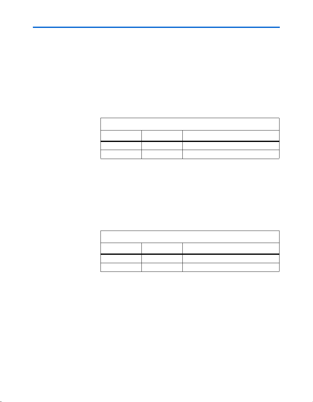
Revision History
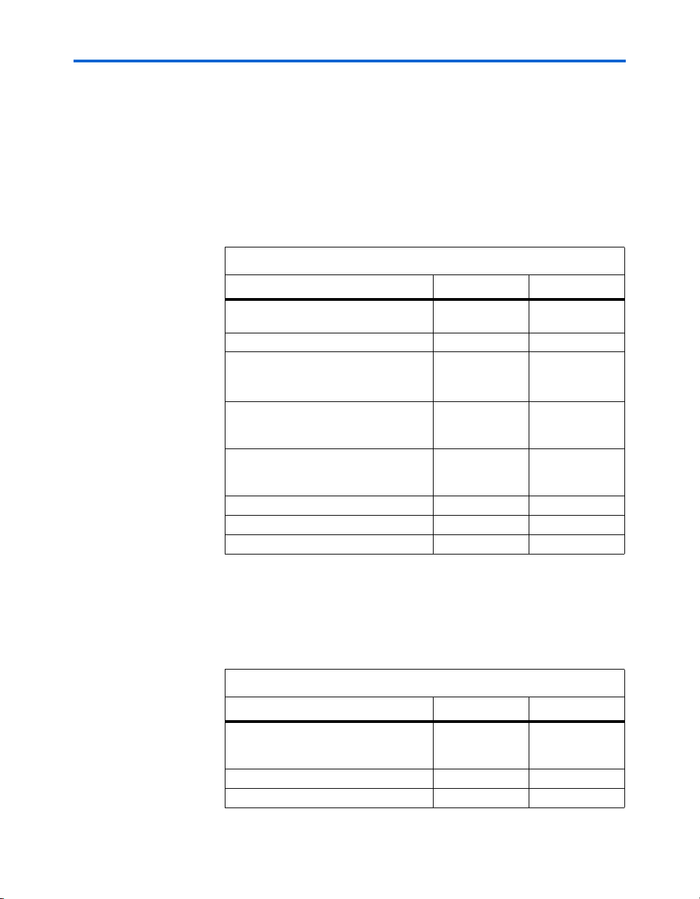
Chapter Date Version Changes Made
All October 2005 1.0 Initial release of this specification.
How to Contact Altera
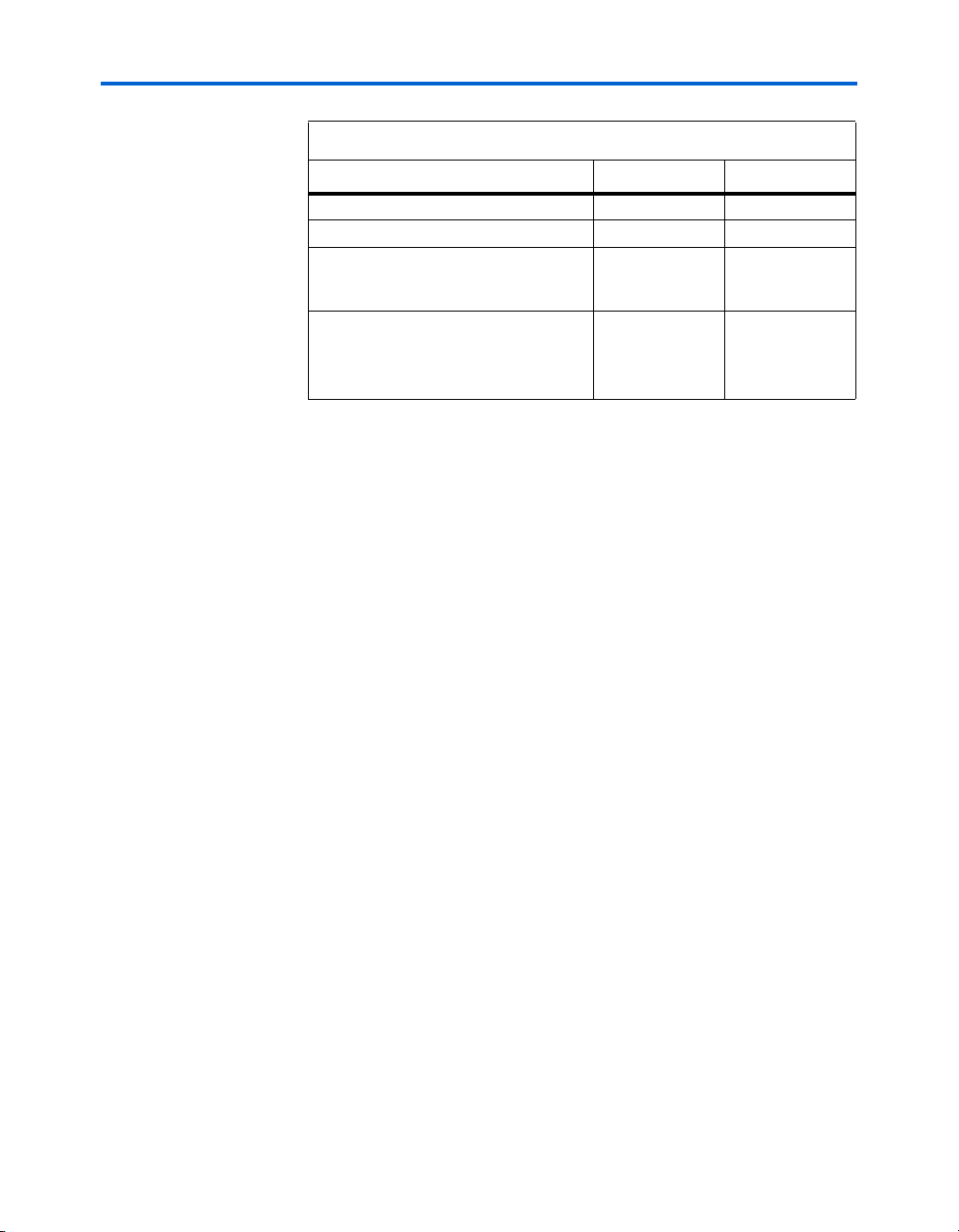
Information Type USA & Canada All Other Locations
Technical support www.altera.com/mysupport/ www.altera.com/mysupport/
Product literature www.altera.com www.altera.com
Altera literature services literature@altera.com literature@altera.com
Non-technical customer
service
FTP site ftp.altera.com ftp.altera.com
The table below displays the revision history for this reference manual.
For the most up-to-date information about Altera® products, go to the
Altera world-wide web site at www.altera.com. For technical support on
this product, go to www.altera.com/mysupport. For additional
information about Altera products, consult the sources shown below.
(800) 800-EPLD (3753)
(7:00 a.m. to 5:00 p.m. Pacific Time)
(800) 767-3753 + 1 408-544-7000
+1 408-544-8767
7:00 a.m. to 5:00 p.m. (GMT -8:00)
Pacific Time
7:00 a.m. to 5:00 p.m. (GMT -8:00)
Pacific Time
Typographic
This document uses the typographic conventions shown below.
Conventions
Visual Cue Meaning
Bold Type with Initial
Capital Letters
bold type External timing parameters, directory names, project names, disk drive names,
Altera Corporation v
Command names, dialog box titles, checkbox options, and dialog box options are
shown in bold, initial capital letters. Example: Save As dialog box.
filenames, filename extensions, and software utility names are shown in bold
type. Examples: f
, \qdesigns directory, d: drive, chiptrip.gdf file.
MAX
SerialLite II Protocol Reference Manual
Page 6

Glossary
Visual Cue Meaning
Italic Type with Initial Capital
Letters
Italic type Internal timing parameters and variables are shown in italic type.
Initial Capital Letters Keyboard keys and menu names are shown with initial capital letters. Examples:
“Subheading Title” References to sections within a document and titles of on-line help topics are
Document titles are shown in italic type with initial capital letters. Example: AN 75:
High-Speed Board Design.
Examples: t
Variable names are enclosed in angle brackets (< >) and shown in italic type.
Example: <file name>, <project name>.pof file.
Delete key, the Options menu.
shown in quotation marks. Example: “Typographic Conventions.”
PIA
, n + 1.
Courier type Signal and port names are shown in lowercase Courier type. Examples: data1,
tdi, input. Active-low signals are denoted by suffix n, e.g., resetn.
Anything that must be typed exactly as it appears is shown in Courier type. For
example:
actual file, such as a Report File, references to parts of files (e.g., the VHDL
keyword
Courier.
1., 2., 3., and
a., b., c., etc.
● • Bullets are used in a list of items when the sequence of the items is not important.
■
v The checkmark indicates a procedure that consists of one step only.
1 The hand points to information that requires special attention.
c
w
r The angled arrow indicates you should press the Enter key.
f The feet direct you to more information on a particular topic.
Numbered steps are used in a list of items when the sequence of the items is
important, such as the steps listed in a procedure.
The caution indicates required information that needs special consideration and
understanding and should be read prior to starting or continuing with the
procedure or process.
The warning indicates information that should be read prior to starting or
continuing the procedure or processes
c:\qdesigns\tutorial\chiptrip.gdf. Also, sections of an
BEGIN), as well as logic function names (e.g., TRI) are shown in
Glossary
This section describes some of the terms used in this manual.
Bit Alignment: The process of selecting the proper sampling position of
incoming bits.
Byte: 8-bit unencoded value that represents raw data intended for, or after,
transmission. All data in the Link layer has the byte as the basic unit.
vi Altera Corporation
SerialLite II Protocol Reference Manual
Page 7

About This Manual
Character: General term used to describe a byte after conversion to its
10-bit encoded value. This term only appears in the context of the
Physical layer.
Code Group: Refers to specific 10-bit values in the context of defining how
to encode and decode. Uses /Dx.y/ and /Kx.y/ notation.
Column: The collection of all lanes during a particular character cycle.
While column is the common term used, it is somewhat confusing in this
specification because all figures show time progressing up/down. Thus
columns are actually seen as rows.
CRC: Cyclic redundancy check. A number derived from, and transmitted
with, a block of data in order to detect data corruption.
Data Packets: One of two possible user packet types transferred through
the user side interface. (The second type is the priority packet.)
Field: A defined portion of a sequence of symbols or ordered sets. Any
particular sequence is defined as a series of fields, each having a specific
purpose.
Lane: A set of differential pairs, one pair for transmission and one pair for
reception.
Lane Alignment: The process of deskewing multiple lanes in a link. Special
characters are used to identify the relationship to other lanes that are
skewed during transmission. Alignment is achieved when all lanes have
the alignment character adjacent to each other.
Lane Bonding: Data payload mapping across multiple lanes which take
place at the transmitter side.
Lane Stripping: The receiver process by which all packet encapsulations
are removed, reversing the transmitter bonding process.
Link: A communications path between two components. An xN link is
composed of N lanes.
Link Management Packets: Used by the SerialLite II protocol to maintain
the link.
Ordered Set: A symbol that is transmitted simultaneously on all lanes at
once; notated with double-vertical lines, as in ||COM||.
Port: A group of transmitters and receivers located on the same chip that
define a link.
Altera Corporation vii
SerialLite II Protocol Reference Manual
Page 8

Glossary
Priority Packets: User packet transmitted/received through the
high-priority user-side interface. The transmission of priority packets
takes precedence over that of data packets.
Sequence: A predefined series of symbols or ordered sets, one following
another. A sequence of symbols is notated using curly braces, for example
{SDP}. A sequence of ordered sets is notated {|TS1|}.
Symbol: A symbolic representation of a specific code group or sequence
notated with a letter or letters, for example COM.
Transfer Size: The number of columns for a contiguous burst of data.
User Packets: A term used to describe data or priority packets
transmitted/received through one of two user-side interfaces.
Word: Used loosely to refer to one byte (8-bit space) as a single unit.
Word Alignment: The process of aligning data to a word boundary.
viii Altera Corporation
SerialLite II Protocol Reference Manual
Page 9

SerialLite II
Specification
Introduction
SerialLite II is a lightweight, chip-to-chip protocol suitable for packet and
streaming data in chip-to-chip, board-to-board, and backplane
applications. This protocol offers low protocol overhead, low gate count,
and minimum data transfer latency. It provides reliable, high-speed
transfers of packets between devices over serial links. The SerialLite II
protocol defines packet encapsulation at the link layer and data encoding
at the physical layer. This protocol integrates transparently with existing
networks, without software support.
Protocol Features
■ Simplex and duplex operation
■ Symmetrical and asymmetrical operation
■ In-band control signalling
■ Supports streaming and packet-based protocols
■ Support for two user packet types: data packet and priority packet
■ Nesting (priority packet within data packet) for time-critical control
packet
■ Support for single or multiple lanes
■ Data packet size: minimum one byte; no maximum.
■ Priority packet size: minimum one byte; no maximum
■ 8B/10B Physical layer encoding
■ Synchronous or asynchronous operation
■ Lane polarity reversal
■ Lane-to-lane reordering for multi-lane operation
■ Packet integrity protection using CRC-32 or CRC-16
■ Payload and idle scrambling
■ Link management packets
■ Error detection
■ Segment retry-on-error for priority packets
■ In-band flow control for priority and data packets
■ Low protocol overhead
■ Low point-to-point transfer latency
■ Inter-frame gaps are not required
Typical Applications
■ Packet or streaming data applications
■ Chip-to-chip connectivity
■ Board-to-board connectivity
Altera Corporation 9
Preliminary
Page 10
Architectural Overview
■ Shelf-to-shelf connectivity
■ Backplane communication
Architectural
Overview
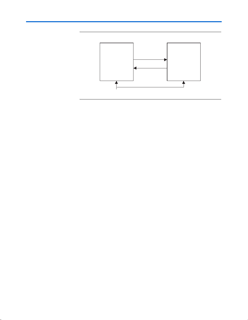
The SerialLite II protocol involves the Data Link layer and the Physical
layer of the OSI layer reference model, as shown in Figure 2–1. The
Physical layer is fully implemented. The link layer can be also be fully
implemented; though the amount of link-layer functionality that is added
to the SerialLite II protocol can be application specific. The SerialLite II
protocol integrates transparently with existing networks and provides a
reliable data transfer mechanism in simple applications that do not need
the layers between the Data Link layer and the Application layer, or that
do not use the OSI model at all.
Figure 2–1. OSI Reference Model Layers
Application
Presentation
Session
Transport
Network
Data Link
Physical
SerialLite II
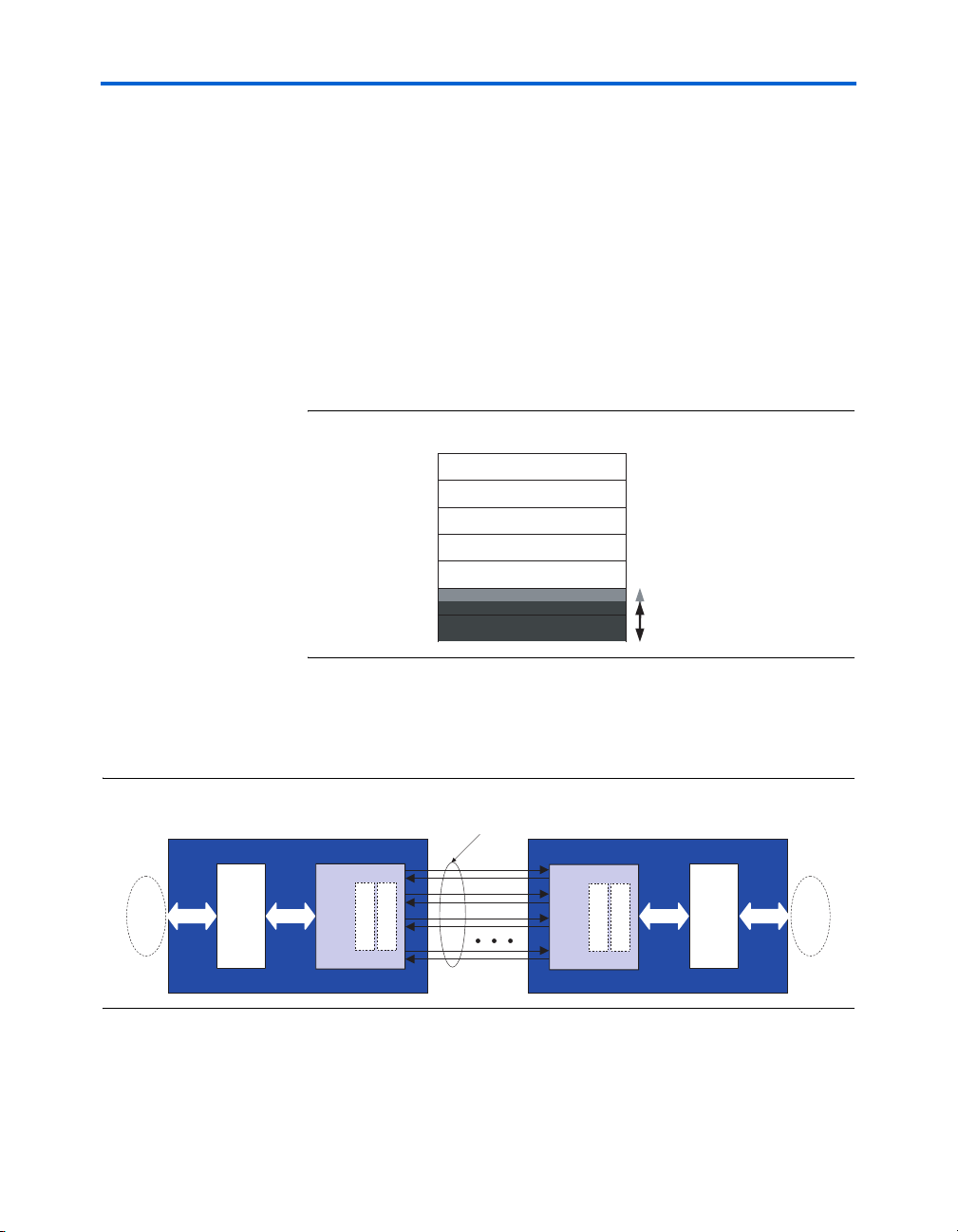
SerialLite II is a general-purpose protocol useful for a wide variety of
applications. The SerialLite II interface consists of a scalable number of
physical data lanes, as shown in Figure 2–2.
Figure 2–2. SerialLite Architecture Overview
One or More
Lanes
User
Application
Link Layer
Logical
Electrical
Physical Layer
Logical
Electrical
Physical Layer
Link Layer
10 Altera Corporation
SerialLite II Protocol Reference Manual
User
Application
Page 11
SerialLite II Specification
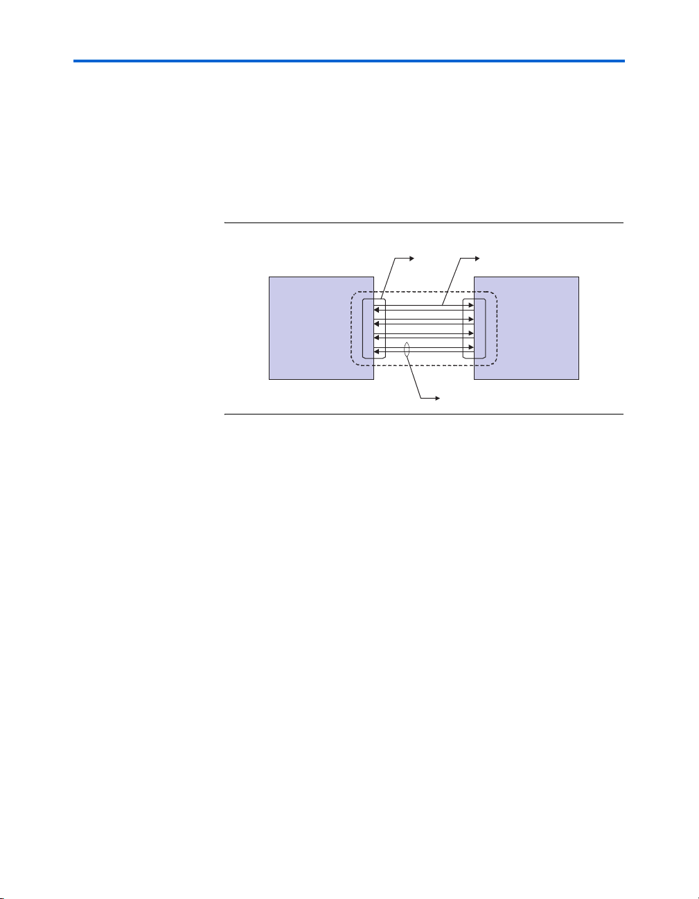
Physical Layer
The Physical layer defines 8B/10B symbols for converting 8-bit user data
characters from the Data Link layer to 10-bit data symbols, as well as
control symbols and idle symbols for inter-packet fill. The Physical layer
also specifies the bit transmission order, and serial-to-parallel and
parallel-to-serial conversion. Figure 2–3 shows an example of the
Physical layer connection.
Figure 2–3. Physical Layer Definition
LinkPort
PHY PHY
Lane
Transmit Direction
■ Serialization of data
■ 8B/10B encoding
■ Link initialization
■ Insertion of clock compensation characters for asynchronous
applications
■ Idle character conversion
■ Payload and idle scrambling
Receive Direction
■ Clock recovery
■ Deserialization of data
■ Character alignment using a comma control symbol
■ 8B/10B decoding
■ Link initialization
■ Lane alignment (for multiple lanes)
■ Check for running disparity error and invalid character error
■ Clock tolerance compensation for asynchronous applications
■ Payload and idle descrambling
Altera Corporation 11
SerialLite II Protocol Reference Manual
Page 12

Physical Layer Description
Data Link Layer
The Data Link layer describes packet encapsulation, link initialization,
lane bonding, lane striping, flow control, and packet retransmission
request commands.
Transmit Direction
■ Packet encapsulation
■ Packet nesting
■ Idle character generation
■ Flow control (optional)
■ CRC generation (optional)
■ Lane striping for multi-lane link
■ Priority packet retry-on-error handling (optional)
Receive Direction
■ Packet encapsulation removal
■ Nested packet separation
■ Lane stripping
■ Idle character deletion
■ CRC verification (optional)
■ Flow control commands generation (optional)
■ Error handling
■ Priority packet retry-on-error commands (optional)
Physical Layer
Description
The Physical layer consists of an electrical sublayer and a logical sublayer.
The electrical sublayer converts the electrical signals from a serial bit
stream into characters and provides a synchronous clock to the logical
sublayer. The logical sublayer handles the character alignment, symbol
encoding, link initialization and training, lane alignment, and clock
compensation.
The SerialLite II protocol uses control characters to identify link
information that is embedded into the data stream. This information
allows multiple channels to be easily bonded together, matching the
application's throughput requirements to the link capacity.
12 Altera Corporation
SerialLite II Protocol Reference Manual
Page 13
SerialLite II Specification
Signal Definitions
Table 2–1 provides a list of the interface signals, including a short
description of their functionality.
Table 2–1. Interface Signals
Signal Direction Description
TD[0-N]
RD[0-N]
Output Transmit data—Carries payload data and in-band
control words. TD connects to RD of the receiving
device.
Input Receive data—Carries payload and in-band control
words. RD connects to TD of the transmitting
device.
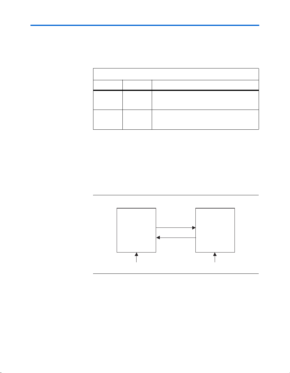
Interface Diagrams
The SerialLite II protocol supports an interface that recovers the clock and
data for a serial bit.
Figure 2–4 shows the SerialLite II protocol in asynchronous mode, where
the clock and data is recovered from the serial bit stream, and each device
has its own reference clock.
Figure 2–4. Asynchronous Clock & Data Recovery
Device A Dev ice B
TD[ 0- N] RD[0 -N]
RD[0 -N] T D[0- N]
REFCLKREFCLK
Figure 2–5 on page 2–14 shows the SerialLite II protocol in synchronous
mode, where the clock and data is recovered from the serial bit stream,
and the reference clock is shared between devices.
Altera Corporation 13
SerialLite II Protocol Reference Manual
Page 14
Physical Layer Description
Figure 2–5. Synchronous Clock & Data Recovery
Device A Device B
TD[ 0- N] RD[0 -N]
RD[0 -N] T D[0- N]
REFCLK
Electrical Specifications
This section defines the electrical specifications for the SerialLite II
Physical layer. The AC electrical specifications are given for the
transmitter and receiver, and cover single- and multi-lane instantiations.
To ensure interoperability between components operating from different
supply voltages or implemented in different technologies, use AC
coupling at the receiver input.
Advisory Note for Electrical Specifications
The parameters for the AC electrical specifications are based on existing
electrical interfaces. For example, SerialLite II can use the XAUI electrical
interface specified in Clause 47 of IEEE 802.3ae-2002, or the CEI electrical
interface specified in Clause 6 of OIF-CEI-02.0. This standard usage
allows electrical designs for SerialLite II to reuse electrical designs from
the XAUI and CEI, suitably modified for applications at the
SerialLite II-specific baud interval and reach described in this
specification.
Where elements of the electrical specification follow the exact XAUI
specification, this document points to the XAUI and CEI documents.
Where there are differences motivated by the frequency range supported
by SerialLite II, the applicable SerialLite II information is provided.
Equalization and Pre-emphasis
The use of high-speed serial links causes the interconnect media to
degrade the signal at the receiver, which produces effects such as
inter-symbol interference (ISI) or data-dependent jitter. The signal loss
14 Altera Corporation
SerialLite II Protocol Reference Manual
Page 15
SerialLite II Specification
can be large enough to degrade the eye opening at the receiver beyond
what is allowed in the specification. To reduce some of these effects, both
transmitter equalization and receiver pre-emphasis can be used.
Driver Characteristics
Refer to IEEE 802.3ae Clause 47.3.3 for XAUI characteristics and
OIF-CEI-02.0 Clause 6.4.1 for CIE characteristics. Tab le 2 –2 describes the
characteristics for other possible frequencies.
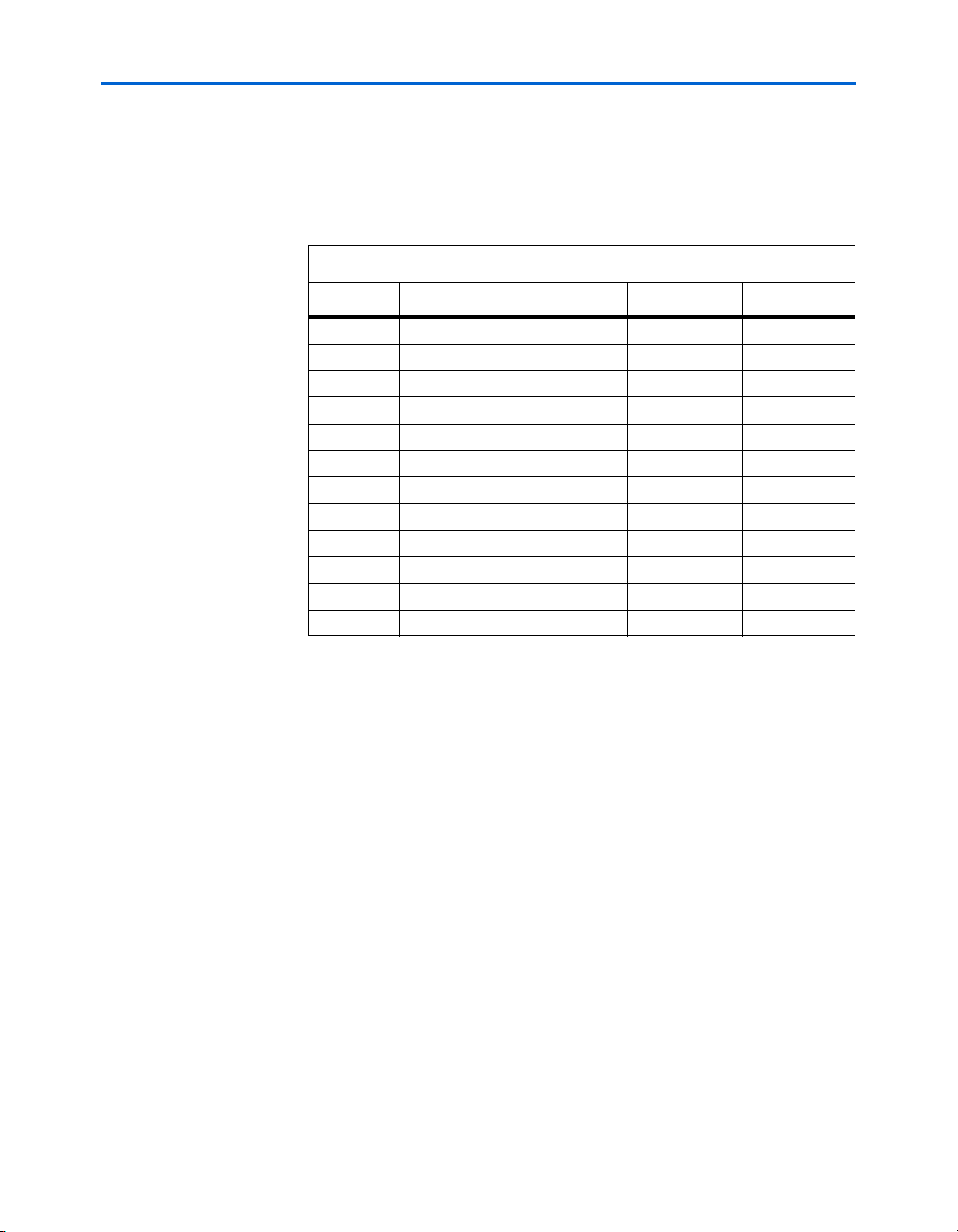
Table 2–2. Driver Characteristics
Parameter Value or Range Units
Bit rate
Tolerance
Unit interval (nominal) [UI] 156 – 1607 pS
Differential amplitude
Maximum
Minimum
Absolute output voltage limits
Maximum
Minimum
Output jitter
Maximum deterministic jitter (JD)
Maximum total jitter (JT)
Transition Time (20% – 80%) 60 – 130 pS
Differential Output Impedance 100 ± 10% Ohm
Differential Pair Output Skew 0 – 15 pS
0.622 – 6.375
±300
1600
400
2.3
-0.4
0.17
0.35
Gbaud
ppm
mV
p-p
mV
p-p
V
V
UI
UI
Receiver Characteristics
Refer to IEEE 802.3ae Clause 47.3.4 for XAUI characteristics and
OIF-CEI-02.0 Clause 6.4.2 for CIE characteristics. Tab le 2 –3 describes the
characteristics for other possible frequencies.
Table 2–3. Receiver Characteristics (Part 1 of 2)
Parameter Value Units
Bit rate
Tolerance 0.622 – 6.375
±300
Unit interval (nominal) [UI] 156 – 1607 pS
Receiver coupling AC
Altera Corporation 15
SerialLite II Protocol Reference Manual
Gbaud
ppm
Page 16
Physical Layer Description
Table 2–3. Receiver Characteristics (Part 2 of 2)
Parameter Value Units
Bit Error Rate 10 –12
Differential Input Impedance 100 ± 10% Ohm
Return loss
Common mode106
Jitter amplitude tolerance
Minimum deterministic
Minimum deterministic plus random
Minimum total
Differential
0.37
0.55
0.65
dB
dB
UI
UI
UI
p-p
p-p
p-p
Interconnect Characteristics
Refer to IEEE 802.3ae Clause 47.3.5 for XAUI characteristics and
OIF-CEI-02.0 Clause 6.A for CIE characteristics.
Electrical Measurement Requirements
Refer to IEEE 802.3ae Clause 47.4 for XAUI and OIF-CEI-02.0 Clause 2 for
CEI.
Symbol Encoding
The SerialLite II protocol encodes physical lanes using the
industry-standard 8B/10B encoding scheme. This approach takes 8-bit
data bytes and encodes them into 10-bit characters for transmission. The
10-bit coding is designed to allow the receiver to be able to recover a clock
signal from the transmitted data. Each 10-bit code has either an equal
number of ones and zeros (balanced) or the number of ones and zeros
differs by two (unbalanced). As the 10-bit code space is larger than the
8-bit data space, two 10-bit values can represent the same 8-bit code
where both 10-bit codes are either balanced or unbalanced. Unbalanced
pairs of 10-bit codes are compliments of each other to have the opposite
number of ones and zeros. Thus allowing the encoding to select between
unbalanced characters to evenly balance a stream of characters with a
maximum run length of five consecutive identical digits.
To maintain a balanced stream of characters, the encoder and decoder
keep a running disparity. Each 10-bit character of a specific code-group is
used for either positive running disparity (RD+) or negative running
disparity (RD-). The encoder selects between the two values based on the
current running disparity and ensures the maximum run length of five is
never violated. Running disparity is also used to detect if the 10-bit code
symbol has been corrupted.
16 Altera Corporation
SerialLite II Protocol Reference Manual
Page 17
SerialLite II Specification
There are two categories of code group:
■ Data code-groups: Any 8-bit byte can be converted into a 10-bit
encoded character.
■ Special code-groups: A limited number of 8-bit values can be
converted into 10-bit control characters.
When a control byte is to be encoded, a separate signal must be asserted
to inform the encoder that it must generate a special code-group, not a
data code-group.
Notation Convention
The 8B/10B transmission scheme uses letter notation to describe the bits
of an unencoded information byte and the one-bit control variable. The
control variable is set to 1 to select a K value from the special code-groups;
it is not set for the D value of the data code-groups. Code-groups are
indicated by the notation ‘Dx.y’ or ‘Kx.y’. See “8b/10b Code Groups” on
page 2–75 for a listing of the possible values and encodings.
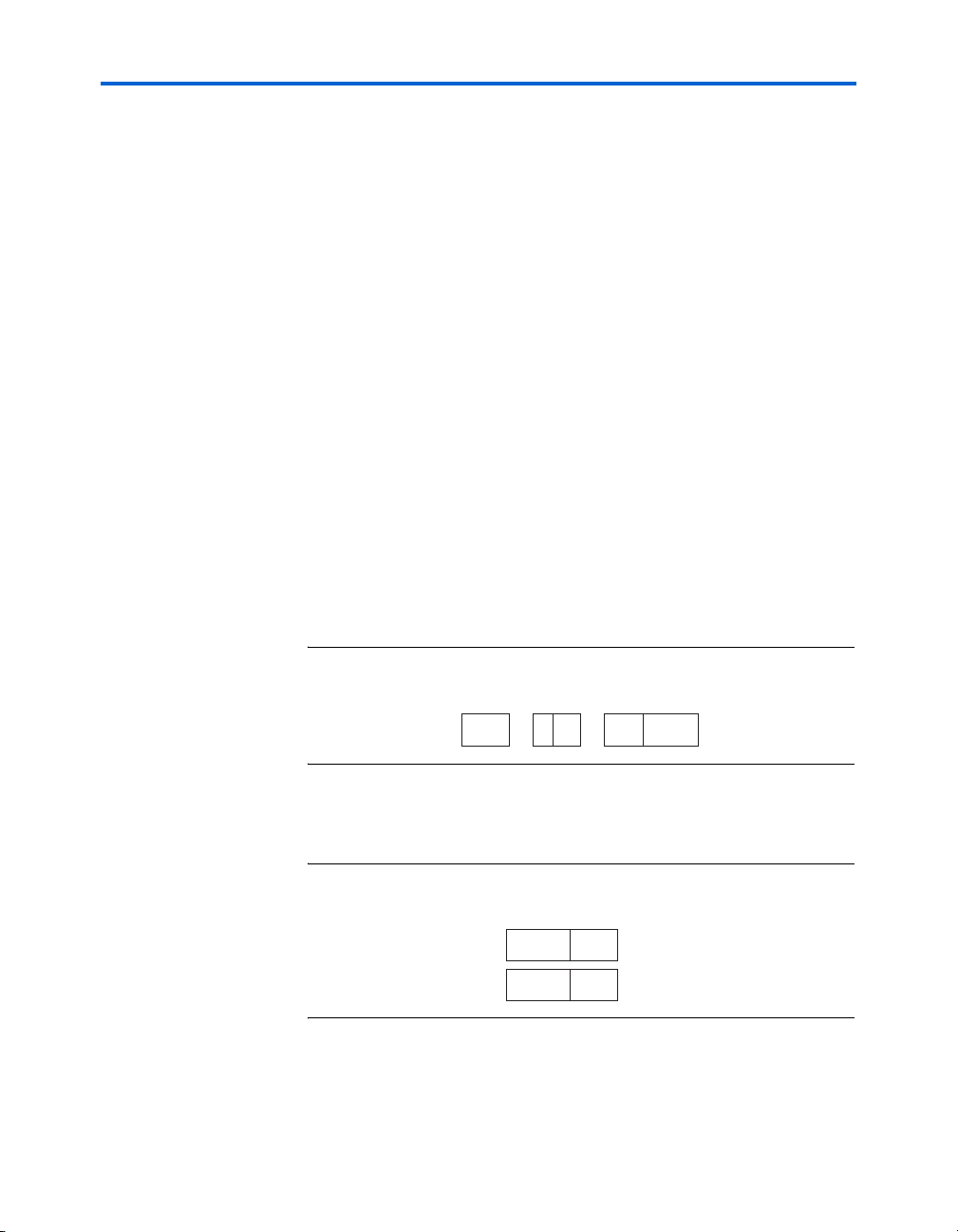
The bit notation of HGF EDCBA is used to indicate the bits of the
unencoded 8-bit value, where A is the least-significant bit (LSB), as shown
in Figure 2–6.
Figure 2–6. Character Notation Example of D30.4
D30.4
yx
4 30 100 11110
HGF EDCBADx.y
The HGF EDCBA bits are translated to the abcdei fghj bits of the 10-bit
transmission code-groups, as shown in Figure 2–7.
Figure 2–7. Code-Group Notation Example of D30.4
Altera Corporation 17
fghjabcdei
0010011110
RD-
1101100001
RD+
SerialLite II Protocol Reference Manual
Page 18
Physical Layer Description
Several terms that are used to describe different entities and combinations
of entities involved in specifying how encoding works. This specification
uses the terms and notation defined in Ta bl e 2– 4.
Table 2–4. Terms and Notation
Term Meaning Notation Example
Byte 8-bit value, prior to 8B/10B
Character 10-bit value, the result of the
Code-group A specific 10-bit encoding of a
Symbol The symbolic representation of a
Sequence A series of symbols that are
Ordered set A character that is placed
Ordered set
sequence
encoding; used to refer to general
data.
encoding of a byte; used to refer to
general data.
specific byte.
specific code-group, placed on a
single lane of an actual
implementation.
transmitted in the given order;
given a shorthand name to refer to
the entire sequence.
simultaneously on all lanes of a
multi-lane implementation.
A series of ordered sets that are
transmitted in the given order, of
which each element appears
simultaneously on all lanes of a
multi-lane implementation.
Dx.y or Kx.y D26.5
K28.5
/x/ /COM/
{x} {SDP}
||x|| ||ALN||
{|x|} {|TS1|}
Transmission Order
Code transmission and reception start with bit ‘a’ of the 10-bit code, as
shown in Figure 2–8 on page 2–19. The order of transmission of multiple
characters across multiple lanes is described under “Multi-Lane
Alignment” on page 2–44.
18 Altera Corporation
SerialLite II Protocol Reference Manual
Page 19
SerialLite II Specification
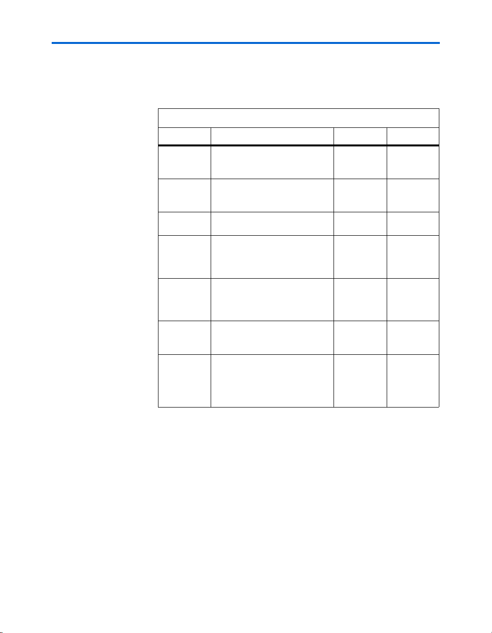
Figure 2–8. 8B/10B Notation Convention and Transmission Order
Transmit Receive
7 6 5 4 3 2 1 0 7 6 5 4 3 2 1 0
C C
HG F ED C B A HGFE DC BA
bc d e i fgh jabcdeifghja
8 7 6 5 4 3 2 1 09
“a” Transmitted First “a” Received First
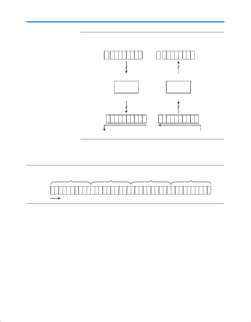
Figure 2–9 shows the transmission of multiple words on a single lane
starting with the first symbol.
Figure 2–9. Single Lane Serial Transmission Order
Symbol 0
Lane
b c d e i f g h j
a b c d e i f g h j
#0
Time
Symbo l 1
a b c d e i f g h j
8b to 10b
Encoder
8+Control
10b to 8b
Decoder
8+Control
10 10
8 7 6 5 4 3 2 1 09
Symbol 2
a b c d e i f g h j
a
Symbo l 3
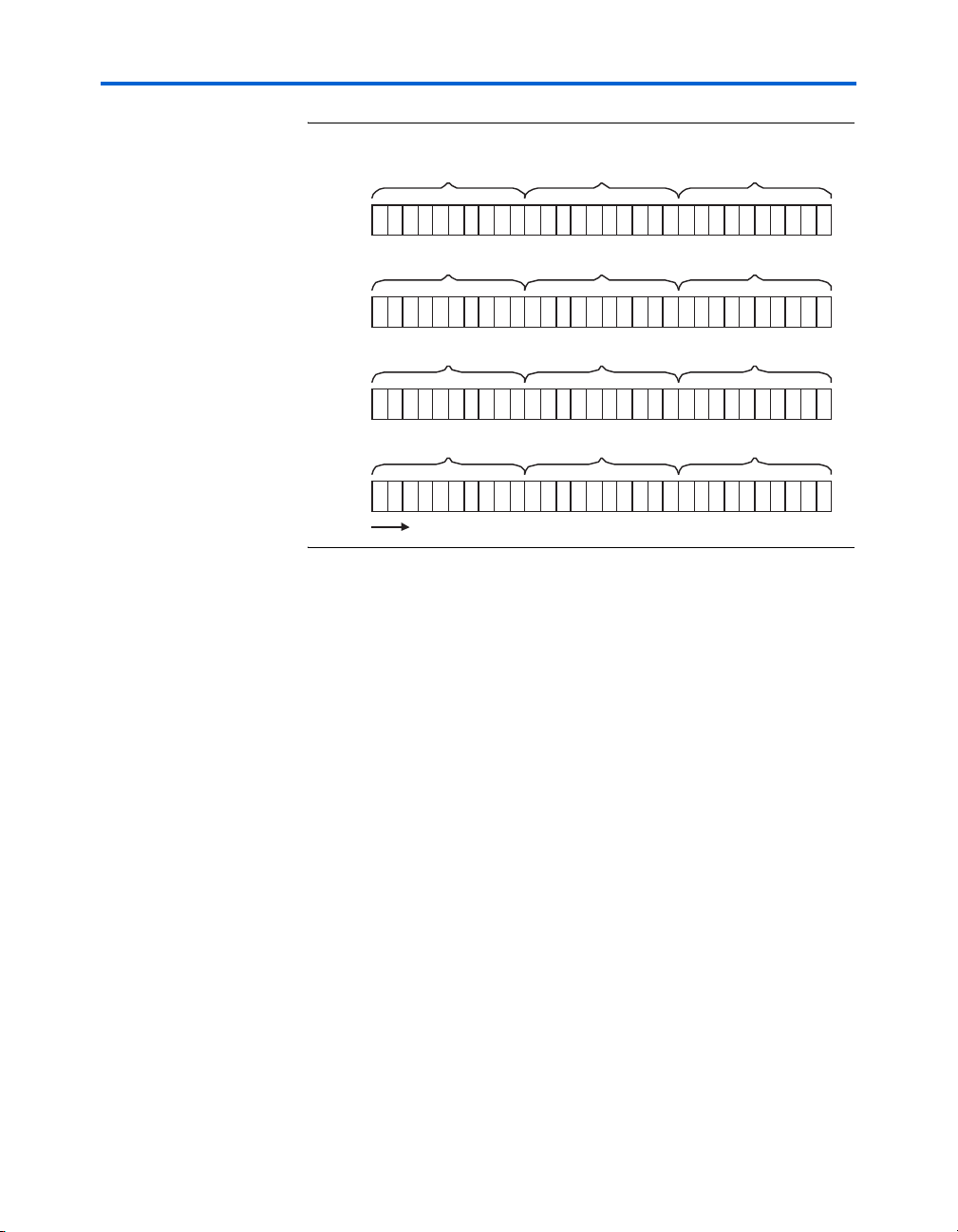
Figure 2–10 on page 2–20 shows the transmission of multiple words
across multiple lanes. The first symbol is transmitted on the lowest lane
followed by the second on next lane until a column is completed.
Altera Corporation 19
SerialLite II Protocol Reference Manual
Page 20
Physical Layer Description
Figure 2–10. Four Lane Serial Transmission Order
Symbol 0
Symbo l 4
Symbol 8
Lane
#0
Lane
#1
Lane
#2
Lane
#3
b c d e i f g h j
a b c d e i f g h j
Symbol 1
b c d e i f g h j
a b c d e i f g h j
Symbol 2
b c d e i f g h j
a b c d e i f g h j
Symbol 3
b c d e i f g h j
a b c d e i f g h j
Time
a b c d e i f g h j
Symbo l 5
a b c d e i f g h j
Symbo l 6
a b c d e i f g h j
Symbo l7
a b c d e i f g h j
a
Symbol 9
a
Symbo l 10
a
Symbo l 11
a
Running Disparity Rules
The SerialLite II rules for running disparity are as specified in Clause 36
of the IEEE 802.3-2002 specification.
Valid and Invalid code-groups
Not every 10-bit value constitutes a valid 10-bit code. The 10-bit space is
only partially populated with valid combinations.
Valid and invalid 10-bit code groups for SerialLite II are as specified in
Clause 36 of the IEEE 802.3-2002 specification. This clause defines both
the data code-group (D code-group) and the special code-group (K
code-group). See “8b/10b Code Groups” on page 2–75 for a complete list
of these groups.
20 Altera Corporation
SerialLite II Protocol Reference Manual
Page 21
SerialLite II Specification
Control Symbols
This section defines the individual symbols used either alone or as part of
control sequences, see Ta bl e 2 –5 . For simplicity, these symbols are used
instead of their associated code groups.
Table 2–5. Description of the Control Symbols
Name Description 8b10b Hex
/COM/ Comma (Sync) K28.5 0xBC
/ALN/ Align K28.3 0x7C
/IDL/ Idle (Skip) K28.0 0x1C
/SPP/ Start of priority packet K28.1 0x3C
/SDP/ Start of data packet K28.2 0x5C
/CPP/ Continuation of priority packet K28.4 0x9C
/CDP/ Continuation of data packet K28.6 0xDC
/SLP/ Start of link management packet K23.7 0xF7
/SUP/ Suspend user packet K27.7 0xFB
/EGP/ End of good packet K29.7 0xFD
/EBP/ End of bad packet K30.7 0xFE
/DAT/ Normal data. Dx.y 0xXX
Comma /COM/
The comma symbol, sometimes called the sync symbol, has a number of
uses. It is used by the physical layer to identify a character boundary, and
it is included in the training sequence for lane initialization and in the
clock compensation sequence.
Align /ALN/
The align symbol is never used alone. It is part of the link deskew
sequence.
Idle /IDL/
The idle symbol is used when no complete transfer of data is available to
send or to fill inter-packet gaps. It is part of the clock compensation
sequence.
Altera Corporation 21
SerialLite II Protocol Reference Manual
Page 22

Physical Layer Description
Start of Data Packet /SDP/
The start of data packet symbol identifies the start of a regular user data
packet.
Start of Priority Packet /SPP/
The start of priority packet symbol identifies the start of a high-priority
user data packet.
Continuation of Data Packet /CDP/
The continuation of data packet symbol identifies the continuation of a
regular user data packet.
Continuation of Priority Packet /CPP/
The continuation of priority packet symbol identifies the continuation of
a high-priority user data packet.
Suspend User Packet /SUP/
The suspend user packet symbol identifies the termination of the burst to
allow for the potential switch of channel number of regular user data
packet.
End of Good Packet /EGP/
The end of good packet symbol identifies the end of a user packet that
was transmitted without errors.
End of Bad Packet /EBP/
The end of bad packet symbol identifies the end of a user packet whose
data is known by the transmitter to be unreliable.
Start of Link Management Packet/SLP/
The start of link management packet symbol identifies a link
management packet.
Control Sequences
The SerialLite II protocol defines a number of control sequences. These
are sequences of code-groups used to mark the beginning and end of a
burst or packets.
22 Altera Corporation
SerialLite II Protocol Reference Manual
Page 23
SerialLite II Specification
f See “User Packet Encapsulation” on page 2–37 for more information on
packet encapsulation, and “Channel Multiplexing” on page 2–56 for
more information on multiplexing channels.
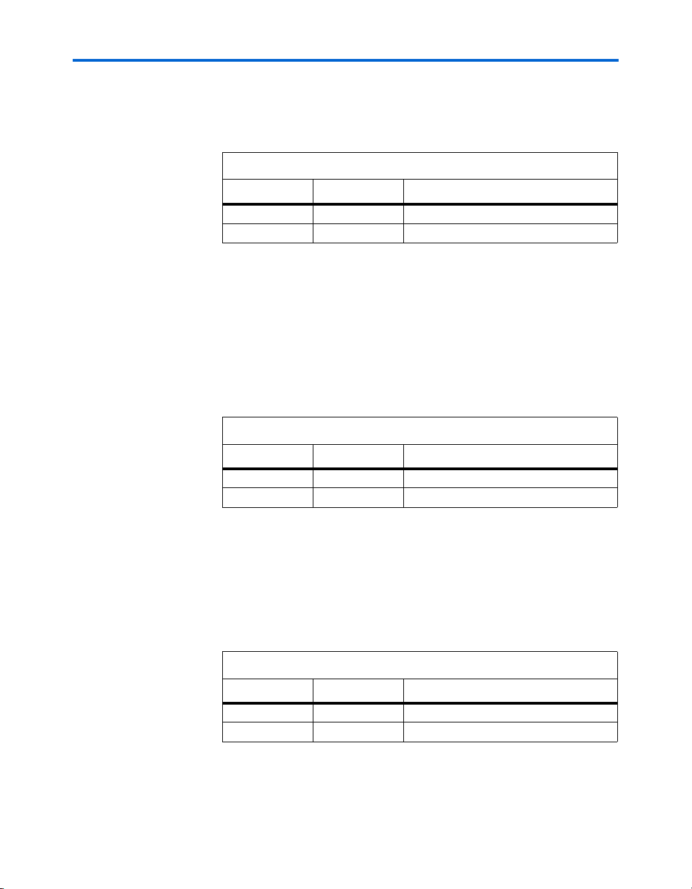
Start of Data Packet Sequence {SDP}
The start of data packet sequence consists of two symbols, as shown in
Table 2–6. The first symbol is the /SDP/ control symbol. The second
symbol is a data code-group that you can use to convey a channel number
for channel multiplexing.
Table 2–6. {SDP} Composition
Field Symbol Description
SDP1 /SDP/ Start of data packet symbol
SDP2 /DAT/ Channel number
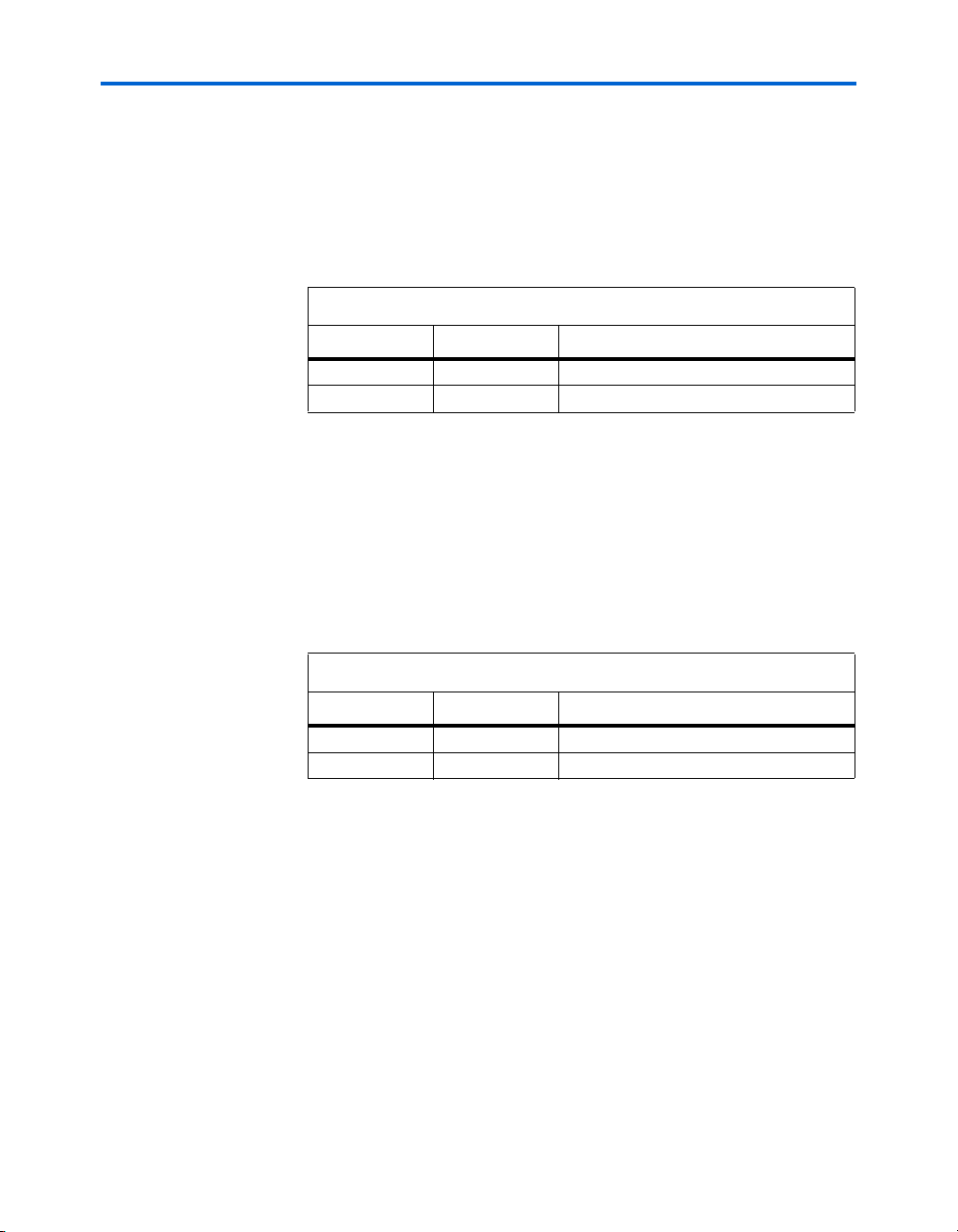
Start of Priority Packet Sequence {SPP}
The start of priority packet sequence consists of two symbols as shown in
Table 2–7. The first symbol is the /SPP/ control symbol. The second
symbol is a data code-group that is divided into two sections. The upper
nibble contains a segment identification number and is used for retry-onerror (see“Retry-on-Error (Optional)” on page 2–64). The lower nibble
can be used to convey a channel number for channel multiplexing.
Table 2–7. {SPP} Composition
Field Symbol Description
SPP1 /SPP/ Start of priority packet symbol
SPP2 /DAT/ Segment identification/channel number
End of Good Packet Sequence {EGP}
The end of good packet sequence consists of two symbols, as shown in
Table 2–8 on page 2–24. It is used to mark the end of a packet that has left
the transmitter without errors. The first symbol is the /EGP/ control
symbol. The second symbol is a data code-group that can be used to
Altera Corporation 23
SerialLite II Protocol Reference Manual
Page 24
Physical Layer Description
verify a channel number for channel multiplexing. For priority packets,
the second symbol contains both the segment identification and channel
number.
Table 2–8. {EGP} Composition
Field Symbol Description
EGP1 /EGP/ End of good packet symbol
EGP2 /DAT/ Segment identification/channel number
End of Bad Packet Sequence {EBP}
The end of bad packet sequence consists of two symbols as shown in
Table 2–9. It is used to mark the end of a packet that the transmitter has
decided is unreliable. The first symbol is the /EBP/ control symbol. The
second symbol is a data code-group that can be used to verify a channel
number for channel multiplexing. For priority packets, the second
symbol contains both the segment identification and channel number. See
“Packets Marked Bad” on page 2–74 for more information on the {EBP}.
Table 2–9. {EBP} Composition
Field Symbol Description
EBP1 /EBP/ End of bad packet symbol
EBP2 /DAT/ Segment identification/channel number
Suspend User Packet Sequence {SUP}
The suspend user packet sequence consists of two symbols as shown in
Table 2–10. The first symbol is the /SUP/ control symbol. The second
symbol is a data code-group that can be used to convey a channel number
for channel multiplexing. The SUP signals the end of a burst, allowing for
a switch to a new channel number or insertion of CRC.
Table 2–10. {SUP} Composition
Field Symbol Description
SUP1 /SUP/ Suspend user packet symbol
SUP2 /DAT/ Channel number
24 Altera Corporation
SerialLite II Protocol Reference Manual
Page 25
SerialLite II Specification
Continuation of Data Packet Sequence {CDP}
The continuation of data packet sequence consists of two symbols as
shown in Ta bl e 2 –11 . The first symbol is the /CDP/ control symbol. The
second symbol is a data code-group that can be used to convey a channel
number for channel multiplexing. The channel number represent the
packet segment to be continued.
Table 2–11. {CDP} Composition
Field Symbol Description
CDP1 /CDP/ Continuation of Data Packet Symbol
CDP2 /DAT/ Channel Number
Continuation of Priority Packet Sequence {CPP}
The continuation of priority packet sequence consists of two symbols as
shown in Ta bl e 2 –1 2. The first symbol is the /CPP/ control symbol. The
second symbol is a data code-group that is divided into two sections. The
upper nibble contains a segment identification number and is used for
retry-on-error (see“Retry-on-Error (Optional)” on page 2–64). The lower
nibble can be used to convey a channel number for channel. The channel
number represents the packet segment to be continued.
Table 2–12. {CPP} Composition
Field Symbol Description
CPP1 /CPP/ Continuation of priority packet symbol
CPP2 /DAT/ Segment identification/channel number
Ordered Sequences
The SerialLite II protocol defines a number of sequences as ordered sets.
As such, each element of the sequence is a symbol that appears on all
lanes simultaneously in a column.
f See “Link Initialization and Training” on page 2–27 for more information
on link training.
Altera Corporation 25
SerialLite II Protocol Reference Manual
Page 26
Physical Layer Description
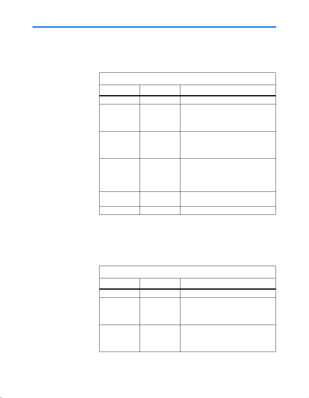
Training Sequence One Ordered Set Sequence {|TS1|}
The first link training sequence consists of eight ordered sets as shown in
Table 2–13. This sequence is used to initialize the links.
Table 2–13. {|TS1|} Composition
Field Ordered Set Description
TC ||COM|| Comma (or Sync) identifier
LN ||DAT|| Lane number. A number from 0 to 255 (in
8-bit space, encoded before transmission,
with 0 representing the most significant
lane)
MLN ||DAT|| Maximum lane number. A number from 0 to
255 (in 8-bit space, encoded before
transmission, with 0 representing a single
lane implementation)
TSZ ||DAT|| Transfer size. Valid numbers are 1, 2, and
4. The transfer size defines the number of
columns for a contiguous burst of data; 1
column, 2 columns, 4 columns, and all
other values are reserved.
RSV 3x||DAT|| Reserved. Set to all zeros (D0.0); repeated
three times
T1 ||DAT|| First training sequence identifier (D10.2)
Training Sequence Two Ordered Set Sequence {|TS2|}
The second link training sequence consists of eight ordered sets as shown
in Ta bl e 2 –1 4. This sequence is used to indicate that link initialization is
complete, and forms part of the link-deskew sequence.
Table 2–14. {|TS2|} Composition
Field Ordered Set Description
TC ||COM|| Comma (or Sync) identifier
LN ||DAT|| Lane number. A number from 0 to 255 (in
8-bit space, encoded before transmission,
with 0 representing the most significant
lane)
MLN ||DAT|| Maximum lane number. A number from 0 to
255 (in 8-bit space, encoded before
transmission, with 0 representing a single
lane implementation)
26 Altera Corporation
SerialLite II Protocol Reference Manual
Page 27

SerialLite II Specification
Table 2–14. {|TS2|} Composition
Field Ordered Set Description
TSZ ||DAT|| Transfer size. Valid numbers are 1, 2, and
4. The transfer size defines the number of
columns for a contiguous burst of data; 1
column, 2 columns, 4 columns, and all
other values are reserved.
RSV 3x||DAT|| Reserved. Set to all zeros (D0.0) repeated
three times
T2 ||DAT|| Second training sequence identifier (D5.2)
Link Deskew Ordered Set Sequence {|TDS|}
This sequence is used in the lane bonding process to allow alignment of
all lanes in a multi-lane link.
Table 2–15. {|TDS|} Composition
Field Ordered Set Description
TDS1 4x {|TS2|} {|TS2|} Order sequence repeated four times
TDS2 ||COM|| Comma (or Sync) identifier
TDS3 ||ALN|| Align identifier
TDS4 2x ||IDL|| Idle identifier repeated twice
Clock Compensation Ordered Set Sequence ({|CC|})
The clock compensation sequence is used by the clock compensation
circuitry to adapt between two clocks having slightly different
frequencies within a specified tolerance. See “Clock Tolerance
Compensation” on page 2–34 for a detailed description.
Table 2–16. {|CC|} Composition
Field Ordered Set Description
CC1 ||COM|| Comma (or Sync) identifier
CC2 3x ||IDL|| Idle (Skip) identifier repeated three times
Link Initialization and Training
Link initialization and training is the process of preparing the link for its
normal operation of transferring data. Single and duplex links have
different state machines. For a duplex link, acknowledgement from the
Altera Corporation 27
SerialLite II Protocol Reference Manual
Page 28

Physical Layer Description
adjacent device is an important part of establishing a reliable link. This
acknowledgement is done through the transmission and receipt of
known character sequences to ensure both the near and far end is
operational. The basic operation is as follows: The near transmitter sends
a sequence to the far receiver. When the far receiver detects the sequence
and has performed the character alignment, it causes the far transmitter
to send the acknowledging sequence. When the near receiver detects this
acknowledging sequence and has completed its character alignment, it
causes the near transmitter to send the acknowledging sequence. For a
multi-lane link, the process is repeated to align and bond the lanes. Both
receivers must be locked and confirm lock to the upstream transmitter
before data is transferred. Figure 2–11 on page 2–28 shows an example of
an acknowledging link.
Figure 2–11. Acknowledging Link Example
Device A Device B
TS1
OR TS2
Res et Char Align
TS2
TS2 TDS
Ac k Char
Alig n
TDS IDLTS1
Lane
Align
IDL
Ac k Lane
Alig n
DA T
Link Up
For a simplex link implementation, no acknowledgement from the
adjacent device is required as data flows in a single direction. Thus, the
receiver must use a self-synchronizing link state machine to lock onto the
incoming data stream without any feedback to the transmitter. The
transmitter assumes that receiver has achieved link initialization and
sends the data. The clock compensation ordered set can be used for lane
bonding. Figure 2–12 shows an example of a self-synchronizing link.
Figure 2–12. Self Synchronizing Example
Device A Device B
DA TDA T C C
Lane
Reset Char Align
Alig n
Link Up
TD[0 -N] RD[ 0- N]
RD[0 -N] TD[ 0- N]
TD[0 -N] RD[0 -N]
TS1
OR TS2
Reset Char A lign
Res et Cha r Ali gn
Ack Char
Align
CCDA T
Lane
Alig n
Lane
Alig n
Ac k Lane
DA T
Link Up
Alig n
IDLTS2 TDS
DA TTS2 TDS IDLTS1
Link Up
28 Altera Corporation
SerialLite II Protocol Reference Manual
Page 29

SerialLite II Specification
Training Sequence
The SerialLite II protocol uses the training sequences {|TS1|}, {|TS2|},
and {|TDS|} during the link and lane initialization process. Training
sequences provide the following important functions.
■ Lane identification—The second field in the training sequence
uniquely identifies the lane number.
■ Link width—The third field in the training sequence identifies the
total number of lanes in a particular link by specifying the maximum
lane number.
■ Transfer size—The fourth field in the training sequence defines the
number of columns for a contiguous burst of data; 1 column, 2
columns, 4 columns, and all other values are reserved.
■ Lane polarity—For {|TS1|}, the TID field normally read as /T1/
(D10.2) is read as /!T1/ (D21.5) when lane polarity is inverted.
Likewise for {|TS2|}, the TID field normally read as /T2/ (D5.2) is
read as /!T2/ (D26.5) when lane polarity is inverted.
Acknowledging Link Training State Machine
Figure 2–13 shows the acknowledging link training state machine.
Altera Corporation 29
SerialLite II Protocol Reference Manual
Page 30

Physical Layer Description
Figure 2–13. Acknowledging Link Training State Machine
Pow er-On Reset
or Hardw are Reset
Link Err or
Res et
Character A lignment
Ac know ledge
Character A lignment
Lane Alignment
Ac know ledge
Lane Alignment
Link-Up
Reset State
The reset state is the first state of the lane initialization state machine. It
can be entered at any time by a power-on reset, hardware reset, or link
error. The transmitter is disabled and its outputs are driven into a
quiescent state (zero-volt differential). The received is initialized.
The receiver discards all received data and flushes any data in progress.
All state machines and registers are set to their initialization values. All
counters, timers, pointers, and expected segment ID for transmission of
priority packets are reset. The link-up status is cleared to indicate the link
is down.
30 Altera Corporation
SerialLite II Protocol Reference Manual
Page 31

SerialLite II Specification
After reset is complete, the receiver/transmitter transitions to the
character alignment state.
Character Alignment State
In this state, bit lock and symbol alignment is achieved by the
configuration of lane polarity. Support for lane polarity inversion is
optional. The transmitter sends the {|TS1|} sequence across all lanes so
that the receiver can start its initialization process. The receiver aligns to
the incoming /COM/ character from either {|TS1|} or {|TS2|} on a lane
by lane basis across all lanes.
The /COM/ character is followed by seven valid data characters. The last
character of the sequence is used to determine the parity. If any of the
parity identifiers in any lane is either /!T1/ (D21.5) or /!T2/ (D26.5), the
receiver for that lane inverts the polarity (if that option is enabled).
Otherwise, it is considered a catastrophic error.
Once at least four consecutive sequences of a /COM/ character followed
by seven valid data characters with the last character of the sequence
being either /T1/ (D10.2) or /T2/ (D5.2) have be en rec eived on each lane ,
the receiver/transmitter transitions to the acknowledge character
alignment state.
Acknowledge Character Alignment State
In this state, the transmitter sends the {|TS2|} sequence across all lanes to
inform the remote port that the near receiver is initialized. The receiver
waits until it receives the {|TS2|} sequence on all lanes.
If a deviation from consecutive {|TS1|} sequences to consecutive {|TS2|}
sequences is detected, the receiver/transmitter transitions to the
character alignment state.
Once the receiver detects at least four {|TS2|} sequences on each lane, the
transmitter sends an additional eight {|TS2|} sequences on each lane and
the receiver/transmitter transitions to the lane alignment state.
Lane Alignment State
In this state, lanes are deskewed for multi-lane links and the lane order is
configured. Support for lane reversal is optional. The transmitter sends
the {|TDS|} sequence on all lanes and the receiver adjusts the lanes so it
is simultaneously receiving the /ALN/ character on all lanes. The
receiver also checks that the lane number embedded in the {|TDS|}
sequence is correct. If it is not correct, the lanes are reversed (if that option
is enabled). If the lane ordering remains incorrect, it is considered a
catastrophic error. For lanes to configure correctly into a bonded link the
third character of {|TS2|} representing the transfer size must be the same
across all lanes. Otherwise it is considered a catastrophic error.
Altera Corporation 31
SerialLite II Protocol Reference Manual
Page 32

Physical Layer Description
If a deviation from consecutive {|TS2|} sequences to consecutive
{|TDS|} sequences is detected, the receiver/transmitter transitions to the
character alignment state.
Once the receiver has simultaneously detected at least four {|TDS|}
sequences on all lanes and the lanes are correctly ordered, the transmitter
sends an additional eight {|TDS|} sequences and the
receiver/transmitter transitions to the acknowledge lane alignment state.
Acknowledge Lane Alignment State
The transmitter sends the ||IDL|| ordered set on all lanes and the receiver
waits to receive the /IDL/ characters all lanes.
Once the receiver has detected at least four ||IDL|| ordered sets and the
transmitter has sent at least eight ||IDL|| ordered sets on all lanes, the
initialization is complete and the receiver/transmitter transitions to the
link-up state.
Link-Up State
The link-up state is the normal operation state. User data is transmitted
and received across the established link. This state is the only one where
link status indicates link-up.
If eight consecutive {|TS1|} sequences are detected by the receiver on any
lane or a link error has been declared, the receiver/transmitter transitions
to the reset state.
Self Synchronizing Link Training State Machine
Figure 2–14 on page 2–33 shows the self-synchronizing training state
machine.
32 Altera Corporation
SerialLite II Protocol Reference Manual
Page 33

SerialLite II Specification
Figure 2–14. Self Synchronizing Link Training State Machine
Pow er-On Reset
or Hardw are Reset
Link Err or
Res et
Character A lignment
Link-Up
Reset State
The reset state is the first state of the lane initialization state machine. It
can be entered at any time by a power-on reset, hardware reset, or link
error. The transmitter is disabled and its outputs are driven into a
quiescent state (zero-volt differential). The received is initialized.
The receiver discards all received data and flushes any data in progress.
All state machines and registers are set to their initialization values. All
counters, timers, pointers, and expected segment ID for transmission of
priority packets are reset. The link-up status is cleared to indicate the link
is down.
After reset is complete, the receiver/transmitter transitions to the
character alignment state.
Character Alignment State
In this state, bit lock and symbol alignment is achieved. The
implementation of the transmitter initialization sequence is user defined.
1 Channel alignment will be defined in a future version of
this specification.
Once at least 64 valid characters are received on each lane, the receiver
transitions to the link-up state. Valid characters can be any special
character or data character.
Altera Corporation 33
SerialLite II Protocol Reference Manual
Page 34

Physical Layer Description
Link-Up State
The link-up state is the normal operation state. User data is transmitted
and received across the established link. This is the only state where link
status indicates link-up.
If a link error is declared, the receiver transitions to the reset state. The
leaky bucket algorithm outlined in the “Leaky Bucket Algorithm” on
page 2–73 is used to monitor data errors causing a link error when an
excessive number of data errors are received.
Clock Tolerance Compensation
Clock tolerance compensation is used for asynchronous
implementations. A transmitter and receiver are at the ends of each
physical lane. The transmitter is driven by a reference frequency with a
given tolerance. The receiver, using a phase-locked loop (PLL) recovers
the transmit clock from the incoming data stream. The reference clock for
the receiver PLL is also of the same frequency with a given tolerance. The
worst-case frequency difference between the transmit and receive clocks
of a lane occurs when one is at the fast end of its range and the other is at
the slow end. For clocks with +/− 300 ppm accuracy, they would be off by
600 ppm, and they would be out of synchronization every 1,666 cycles.
With a tolerance of +/− 100 ppm, the worst-case scenario has the clocks
going out of synchronization every 5,000 cycles. The following formula
calculates the smallest interval at which the two clocks can remain in
synchronization for a given frequency tolerance.
Clock Offset Frequency Calculation
1 000 000,,()
ClockOffsetFrequency
To compensate for this lack of synchronization, an ‘elastic’ buffer is
placed in the receive path. Data is written into the buffer using the
recovered transmit clock, and data is read out of the buffer using the
receive reference clock. A clock tolerance compensation sequence {|CC|}
is inserted by the transmitter into the data stream at the clock offset
frequency. The ‘elastic’ buffer compensates for the differences between
the two clocks by dropping the {|CC|} sequence. The input side of the
buffer operates in the recovered clock domain; the output side operates in
the receive clock domain. If the recovered clock is faster than the reference
clock, the clock tolerance compensation is satisfied with the removal of
{|CC|}. Otherwise, if the recovered clock is slower than the reference
clock, the receive data path is flow controlled until more data is available.
Clock Tolerance Compensation Rules
The following clock tolerance compensation rules must be followed:
34 Altera Corporation
SerialLite II Protocol Reference Manual
=
-----------------------
2n×()
Page 35

SerialLite II Specification
1. All lanes must have the same frequency.
2. The receiver removes any {|CC|} sequence.
3. The transmitter must send one clock compensation sequence
({|CC|}) at each scheduled interval.
4. The transmitter must schedule insertion at least once every 1,666
columns in case of +/- 300 ppm, or at least once every 5,000 columns
in case of +/- 100 ppm.
5. The transmitter must insert a clock compensation sequence into all
lanes simultaneously.
6. The clock compensation sequence has the highest transmission
priority and can interrupt any transmission. It is inserted
irrespective of whether a frame is in transmission or is an idle
period.
Figure 2–15 shows an example of the clock tolerance compensation
sequence insertion.
Figure 2–15. Clock Tolerance Compensation Insertion Example
COM IDL IDL IDL
Data Packet CC Data Packet Priority Packet Idle Data Packet
Scrambling (Optional)
Scrambling can reduce EMI by eliminating repeating characters, which
has a great effect at high data rates. A linear feedback shift register (LSFR)
is used as a pseudo-random number generator to scramble the data,
using the G(x) = X16 + X5 + X4 + X3 + 1 polynomial.
The transmitted bits are XORed with the output of the LFSR in the data
stream. At the receiver, the data stream is again XORed with an identical
scrambler to recover the original bits. To synchronize the transmitter to
the receiver, the COM character initializes the LFSR with the initial seed
of 'hFFFF XORed with the lane number (LN).
Rules for Scrambling
The following scrambling rules must be followed:
Altera Corporation 35
SerialLite II Protocol Reference Manual
Page 36

Data Link Layer Description
1. All data characters are scrambled, except those contained in the
training pattern.
2. The special characters are not scrambled.
3. The COM character initializes the LFSR with value of 0xFFFF
XORed with the lane number (LN).
4. The LFSR advances by 8-bit shifts for each data and special
character, except for the IDL (skip) control symbol.
5. The LFSR scrambling operation acts independently for each lane.
Data Link Layer
Description
This sections describes the Data Link layer of the SerialLite II protocol.
Packet Description
The SerialLite II protocol supports two different packet types: user
packets and link management packets.
User Packets
User packets carry either high-priority user data or regular user data.
User Packet Types
The SerialLite II protocol supports two different user packet types: data
packets and priority packets. A priority packet contains high-priority
data or status information and takes precedence over regular data
packets. Retry-on-error is an added benefit of priority packets to handle
error conditions and increase reliability of the link. Typically, data packets
are better suited for carrying a continuous flow of packets with a low
latency requirement.
User Packet Length
Table 2–17 shows the supported lengths for the user packet types.
Table 2–17. User Packet Length Range
Packet Type Minimum Frame Length Maximum Frame Length
Data 1 character Unlimited
Priority 1 character Unlimited
36 Altera Corporation
SerialLite II Protocol Reference Manual
Page 37

SerialLite II Specification
User Packet Data Flow
A ‘cut-through’ data flow must be implemented for data packets.
Meaning that packet data is transmitted as soon as enough data has been
received to fill a column, without waiting for the entire packet to be
delivered to the transmitter. This approach provides the lowest latency.
Priority packets are broken into segments and sent across the link. The
N
size of the segment is defined to be 2
columns with the smallest being
eight columns.
A ‘store-and-forward’ data flow must be implemented for priority
packets segments. Meaning that no packet data is transmitted until the
entire segment has been delivered to the transmitter. However, priority
packets less than, or equal to, segment size are buffered before
transmission. This buffering is required to support the retry-on-error
option, which is only allowed for priority packets (see “Retry-on-Error
(Optional)” on page 2–64).
User Packet Encapsulation
The SerialLite II protocol encapsulates data and priority packets by
wrapping start- and end-of-packet sequences around them. To mark a
start of packet, both the user and priority data have a 2-byte sequence
appended to them. The user data is preceded by a start-of-data packet
sequence {SDP} while the priority data uses the start-of-priority packet
sequence {SPP}. The second byte located in the start-of-packet sequences
is for segment identification and channel number as defined in Tables 2–6
and 2–7. To mark the packet valid, the end-of-good packet sequence
{EGP} is appended to the tail of the packet, while the end-of-bad packet
sequence marks the end of a corrupted packet. The second byte in the
{EGP}, {EBP} control sequences is used to verify that the segment
identification and channel number was received without corruption as
defined in Tables 2–8 and 2–9.
The IDL characters are inserted to maintain the proper location for control
words. Optionally, a CRC can be generated and appended to the sequence
marking the end of the user packet to protect against errors. Figure 2–16
on page 2–38 shows an example of user data packet encapsulation.
Altera Corporation 37
SerialLite II Protocol Reference Manual
Page 38

Data Link Layer Description
(2)(1)
)
Figure 2–16. User Packet Encapsulation
User Packet
User Packet
User Packet
[IDL]
[IDL] SDP1 EGP1 SDP2 EGP2
CRC
Notes to Figure 2–16:
(1) IDL is required to align the control words to the proper location.
(2) The CRC is optional.
Figure 2–17 shows an example of packet activity during transmission.
Idle refers to the transmitted IDL characters when data is unavailable.
Figure 2–17. Sample Packet Activity
SDP Data Payload EGP CRC SPP Priority Payload EGP CRC
Idle Data Packet Idle Data Packet Idle Priority Packet Idle Idle Data Packet
Note to Figure 2–17:
(1) The CRCs are optional.
(1) (1
Link Management Packets
The link management packets (LMP) are optional and provide two link
control mechanisms: flow control and retry-on-error.
The link management packets are generated and processed in the Data
Link layer and are not intended to be accessible by the user interface. Link
management packets can nest within a user data or priority packet. See
“Nesting Packets” on page 2–42 for more information.
Link Management Packet Identification
The SerialLite II protocol identifies link management packets by
prepending the start-of-link management packet symbol (SLP) to the
payload, as shown in Figure 2–18 on page 2–39.
38 Altera Corporation
SerialLite II Protocol Reference Manual
Page 39

Figure 2–18. Link Management Packet Encapsulation
Link Management Packet Size
The link management packet has a fixed length of four bytes: a single byte
identifier followed by three bytes of payload.
Link Management Packet Payload Format
Table 2–18 shows the link management packet payload format using the
following parameters:
■ FC_TIME = Flow control time
■ ACK = Acknowledgement
■ NACK = Negative acknowledgement
■ SID = Segment identification
■ BIP-8 = 8 bits of bit interleaved parity
■ CLASS = Packet type class
Table 2–18. Link Management Packet Format
SerialLite II Specification
SLP Link Management Packet Payload
Bits
[23:20] [19:16] [15:12] [11:8] [7:4] [3:0]
Type Parameter Description Protection
Flow control packet 0x1 CLASS FC_TIME BIP-8
Retry-on-error control packet 0x2 CLASS 0x0 SID BIP-8
Link Management Packet Type (LMP[23:20])
SerialLite II currently has the following management packets defined:
■ Flow Control Packets (Link Packet Type = 0x1); see detailed
description in “Flow Control (Optional)” on page 2–61.
■ Retry-on-Error Control Packets (Link Packet Type = 0x2); see
detailed description in “Retry-on-Error (Optional)” on page 2–64.
Link Management Packet Parameter (LMP[19:8])
This field contains parameters specific to the type of link management
packet. See “Flow Control (Optional)” on page 2–61 and “Retry-on-Error
(Optional)” on page 2–64 for details.
Altera Corporation 39
SerialLite II Protocol Reference Manual
Page 40

Data Link Layer Description
Link Management Packet Protection (LMP[7:0])
SerialLite II uses 8 bits of bit interleaved parity (BIP-8) to protect the link
management packet. BIP-8 covers both the link packet type and the link
packet parameter fields, as shown in Figure 2–19.
Figure 2–19. BIP-8 Coverage
BIP-8 Coverage
Type BIP-8
Parameter
The BIP-8 is calculated using even parity over all bits of the previous
16-bits of the link management packet payload.
BIP-8 [7] = LMP Bit[7] =
BIP-8 [6] = LMP Bit[6] =
BIP-8 [5] = LMP Bit[5] =
BIP-8 [4] = LMP Bit[4] =
BIP-8 [3] = LMP Bit[3] =
BIP-8 [2] = LMP Bit[2] =
BIP-8 [1] = LMP Bit[1] =
BIP-8 [0] = LMP Bit[0] =
LMP Bit[23] xor LMP Bit[15]
LMP Bit[22] xor LMP Bit[14]
LMP Bit[21] xor LMP Bit[13]
LMP Bit[20] xor LMP Bit[12]
LMP Bit[19] xor LMP Bit[11]
LMP Bit[18] xor LMP Bit[10]
LMP Bit[17] xor LMP Bit[9]
LMP Bit[16] xor LMP Bit[8]
The receiver calculates the syndrome by XORing all link management
packet payload bytes.
Syndrome [7] = LMP Bit[23] xor LMP Bit[15] xor LMP Bit[7]
Syndrome [6] = LMP Bit[22] xor LMP Bit[14] xor LMP Bit[6]
Syndrome [5] = LMP Bit[21] xor LMP Bit[13] xor LMP Bit[5]
Syndrome [4] = LMP Bit[20] xor LMP Bit[12] xor LMP Bit[4]
Syndrome [3] = LMP Bit[19] xor LMP Bit[11] xor LMP Bit[3]
Syndrome [2] = LMP Bit[18] xor LMP Bit[10] xor LMP Bit[2]
Syndrome [1] = LMP Bit[17] xor LMP Bit[9] xor LMP Bit[1]
Syndrome [0] = LMP Bit[16] xor LMP Bit[8] xor LMP Bit[0]
In the absence of any errors, the syndrome equals zero.
Effect of Link Management Packet Corruption
A link management packet that has a BIP-8 error is discarded. The impact
of a corrupted link management packet depends on its type.
40 Altera Corporation
SerialLite II Protocol Reference Manual
Page 41

SerialLite II Specification
f Refer to “Effect of Link Management Packet Corruption” on page 2–64
and “Effect of Link Management Packet Corruption” on page 2–69 for
details.
Idle Generation
The transmitter sends idles across the link when there is no packet
information or special ordered sets to be sent.
There are four scenarios where IDL characters are transmitted:
1. During the link initialization and training. See “Link Initialization
and Training” on page 2–27 for more information.
2. There is no user data to transmit and idles are needed as
inter-packet fill, as shown in Figure 2–20.
Figure 2–20. Idle Used as Inter-Packet Fill
SDP
User Data
EGP Idle Idle SDP User Data EGP Idle
The current packet must finish or be interrupted with a break-packet
sequence. The transmission of regular packet data can be resumed
with the CDP or start of a user packet (SDP or SPP). Either all zero
bytes or the special /IDL/ characters are injected between packets.
The idle data must be ignored and dropped by the receiver. All
running disparity errors are counted as a data error as the status of
the link is monitored.
To reduce EMI, sending all zero ordered sets as inter-packet fill with
scrambling enabled is recommended. This option eliminates
repeating characters, which has great effect at high data rates.
For simpler implementations, the transmitter could choose to inject
only ||IDL|| ordered sets between packets or segments. The receiver is
required to discard all zero ordered sets between packet segments
without raising an error.
3. When data or priority packets are interrupted at the system
interface, or when the transmit link layer device under-runs, or
when the flow control command is received.
Altera Corporation 41
SerialLite II Protocol Reference Manual
Page 42

Data Link Layer Description
y
Figure 2–21. Idle Inserted When User Packet Is Interrupted
SDP User Data EGP User Data Idle Idle Idle
Interruption (or under-run)
stem interface
at the s
4. The IDL symbol is used to fill the idle lanes when a portion of a
column is idle before an end of packet.
Data Transmission Priority
The following is a list of the priority order for all data transfers:
1. Clock compensation sequence
2. Training patterns
3. Link management packet—flow control
4. Link management packet—retry-on-error
5. User priority packet
6. User data packet
7. Idles
Nesting Packets
To reduce delays in transmitting time-critical control packets, SerialLite II
inserts high priority packets into a data packet that is already in
transmission (nests the packets). Link management packets have the
highest packet priority and do not require an escape sequence before
insertion. Figure 2–22 on page 2–43 shows the double-nesting of a link
management packet inside a user priority packet, which in turn is nested
in a user data packet.
42 Altera Corporation
SerialLite II Protocol Reference Manual
Page 43

Figure 2–22. Packet Nesting Example
SDP Data Payload EGP
SDP SPPSUP EGPEGP CDPSLP Link ManagementPr io r i ty Pr io r i ty Dat aDat a
Packet Nesting Rules
The following packet nesting rules must be followed:
1. Nested packets must be started on lane number 0 of a new column.
2. Priority packets cannot be nested in other priority packets.
3. Data and priority packets must follow the packet interleaving rules
as defined in “Packet Interleaving Rules” on page 2–43.
SerialLite II Specification
SLP Link Management
SPP Prioir ity Payload EGP
Interleaved Data Packets
For applications that require bursting and nesting, SerialLite II allows the
the transmission of packets to be suspended and continued. Interleaving
is supported for both priority and data packets. The suspend user packet
(SUP) character interrupts the current packet and continuation of data
packet (CDP) and continuation of priority packet (CPP) identifies the
switch to a different channel address. For more information on channel
multiplexing see “Channel Multiplexing” on page 2–56.
There will be an impact on bandwidth efficiency as additional overhead
is associated with suspending and continuing packets. To minimize the
overhead impact, switch between packet channel numbers on large
bursts. Suspending and continuing to the same channel number is
allowed, but it consumes additional bandwidth. The suspension of a
priority packet must be done on the segment size boundary.
Packet Interleaving Rules
The following packet interleaving rules must be followed:
1. The suspend user packet sequence {SUP} must be transmitted on
lane number 0.
Altera Corporation 43
SerialLite II Protocol Reference Manual
Page 44

Data Link Layer Description
2. The continuation of packet sequences {CDP} and {CPP} must be
transmitted on lane number N-2 of a new column similar to SDP
and SPP.
3. The break must occur on a data burst boundary defined by the
transfer size. The data transfer before the break can not be partially
filled with IDL characters, except upon then end-of-packet.
4. If the CRC option is enabled, the bytes are placed immediately
following EGP, EBP, or SUP.
5. Suspending the transfer of a priority packet must be on the segment
size boundary.
Multi-Lane Alignment
SerialLite II allows the data path to be transparently sent across the link
with in-band overhead carrying control information. For a multi-lane
link, the most significant byte (MSB) of the user interface is transmitted
on the most significant lane. The user data must present data to the user
interface following the big-endian convention. Symbols are transmitted
such that the first byte is sent on lane number 0, the second byte on lane
number 1, and so on. The mapping is simplified for a single lane
implementation as it is a degenerative case.
Multi-Lane Alignment Rules for Packets
The following multi-lane alignment rules must be followed:
1. The start-of-packet sequences for user packets ({SDP}, {SPP}, {CDP},
and {CPP}) begin in lane number N-2.
2. If a packet ends before the end of a column boundary, all remaining
unused lanes to the {EGP} are filled with IDL characters.
3. The end-of-packet sequences ({EGP} and {EBP}) and suspend-packet
sequence ({SUP}) are transmitted in lane number 0.
4. Payload protection {CRC} is appended to either {EGP}, {EBP}, or
{SUP}.
5. The start-of-packet sequence for link management packets begin in
lane number 0.
6. Mixing user data and control symbols is not allowed, except for IDL
at the end of a user packet.
44 Altera Corporation
SerialLite II Protocol Reference Manual
Page 45

SerialLite II Specification
7. Link management packets can only be followed by IDL in the same
column.
8. IDL characters are allowed to span entire columns and fill
inter-packet gaps.
9. Different payload packet types (between data, priority, and link
management packets) cannot share columns.
10. {SUP}, {EGP}, and {EBP} can share the same column as {SPP}, {SDP},
{CPP}, and {CDP}.
Data Transmission Rules
The following data transmission rules must be followed:
1. Data packets can be interrupted on a column boundary, and IDL
characters are transmitted in response to flow control requests
(“Flow Control (Optional)” on page 2–61), or user interface
under-runs.
2. Priority packets can be interrupted on a segment size boundary, and
IDL characters are transmitted in response to flow control requests
(“Flow Control (Optional)” on page 2–61), or user interface
under-runs.
3. Link management packets can be inserted on any column boundary
for both priority and data packets.
4. If packets are nested, the nested packet cannot share a column with
the interrupted data. Meaning that the interrupting packet must be
started on a new column. Once the nested packet is complete, the
interrupted packet must resume on a new column.
5. When data partially fills a column at the end-of-packet, the gap
must be filled with /IDL/ characters. /IDL/ bytes used for padding
and visible to the user are replaced with all zeros.
6. The CRC calculation only covers columns containing user data.
Lane Alignment Examples
For the examples in this section, a column of data aligned across all lanes
during a particular character cycle is shown pictorially as a row.
Switching between control and data can occur in every column.
Altera Corporation 45
SerialLite II Protocol Reference Manual
Page 46

Data Link Layer Description
Single Lane Transmission for Packet Applications
Figure 2–23 shows an example of transmission with only one physical
lane.
Figure 2–23. Typical Data Flow of Single-Lane Link
Lane
#0
Time
IDL
SDP1
SDP2
D0
D1
D4
D5
D6
EGP1
EGP2
CRC1
CRC2
IDL
IDLD4Idles
IDL
SDP1
SDP2
D0
D1
SUP1
SUP2
CRC1
CRC2
SPP1
SPP2
PD0
PD1
PD2D2
PD3D3
EGP1
EGP2
CRC1
CRC2
CRC3
CRC4
CDP1
CDP2
D2
SLP
LD0
LD1
LD2
D3
EGP1
EGP2
CRC1
CRC2
IDL
Prior ity
Packet
Link Mgmt
Packet
Dx
PDx
LDx
Data Payload
Prior ity Payload
Link Mgmt Payload
Multiple Lane Transmission for Packet Applications
Figures 2–24 through 2–27 show examples of multi-lane alignment.
46 Altera Corporation
SerialLite II Protocol Reference Manual
Page 47

Figure 2–24. Typical Data Flow of Two-Lane Link
Lane#0Lane
Time
SDP1
D0
D2
D4
D6
EGP1 EGP2
CRC1 CRC2
IDL ID L
IDL ID L
SDP1 SDP2
D0 D1
SUP1 SUP2
CRC1 CRC2
SPP1 SPP2
PD0
PD2 PD3
EGP1
CRC1 CRC2
CRC3 CRC4
CDP1 CDP2
D2
SLP LD0
LD1 LD2
D4
EGP1 EGP2
CRC1 CRC2
IDL
#1
SDP2
D1
D3
D5
IDL
PD1
EGP2
D3
IDL
IDL
Idles
Prior ity
Packet
Link Mgmt
Packet
PDx
LDx
SerialLite II Specification
Dx
Data Payload
Prior ity Payload
Link Mgmt Payload
Altera Corporation 47
SerialLite II Protocol Reference Manual
Page 48

Data Link Layer Description
Figure 2–25. Typical Data Flow of Three-Lane Link
Lane
#0
Time
IDL
D0
D3
D6
EGP1 EGP2 CRC1
CRC2 ID LIDL
IDL
IDL
D0
SUP1 SUP2
CRC2
PD0
PD2
EGP1
CRC2 CRC3 CRC4
D3
SLP LD0 LD1
LD2
D6 IDLD7
EGP1 EGP2 CRC1
CRC2
IDL
Lane
SDP1
SDP1 SDP2
SPP1 SPP2
PD0
PD2 PD3
EGP2
CDP1 CDP2IDL
Lane
#1
SDP2
D1 D2
D4
IDL
IDL ID L
IDL ID LIDL
D1 D2
D4
IDL ID L
IDL ID L
IDL
IDL
CRC1
PD1
CRC1
IDL
#2
D5
D5
Idles
Prior ity
Packet
Link Mgmt
Packet
Dx
PDx
LDx
Data Payload
Prior ity Payload
Link Mgmt Payload
48 Altera Corporation
SerialLite II Protocol Reference Manual
Page 49

Figure 2–26. Typical Data Flow of Four-Lane Link
Lane#0Lane
Time
IDL
D0
D4
D8
EGP1 EGP2
IDL ID L
D0 D3
SUP1 SUP2
IDL ID L
PD0
PD4
EGP1
CRC3 CRC4
SLP
PD1
PD5
EGP2
D4 D5 D6 D7
LD0 LD1 LD 2
D8 D9 D10
Lane#2Lane
#1
IDL
SDP1
D1
D5
IDL
CRC1 CRC2
SDP1 SDP2
D1 D2
CRC1 CRC2
SPP1 SPP2
CRC1 CRC2
CDP1 CDP2
CRC1 CRC2EGP1 EGP2
D2
D6
IDL IDLIDL ID L
IDL IDLIDL ID L
IDL IDLIDL ID L
IDL IDLIDL ID L
IDL
PD2
PD6
#3
SDP2
D3
D7
IDL
PD3
PD7
IDL
IDLID L ID L ID L
Idles
Prior ity
Packet
Link Mgmt
Packet
SerialLite II Specification
Data Payload
Dx
PDx
Prior ity Payload
Link Mgmt Payload
LDx
Figure 2–27. Typical Data Flow of Eight-Lane Link
Lane#0Lane
Time
IDL
D0
D8
D16
EGP1 EGP2
D0
SUP1 SUP2
PD0
PD8 PD 9
EGP1 EGP2 CDP1 CDP2
SLP LD0
D16
EGP1 EGP2 IDL
PD1 PD5
D17 D18 D19
Lane
#1
IDL
D1 D5
D10 D11
D9
IDL
CRC1 CRC2
D1
CRC1 CRC2 ID L
PD2
PD10 PD 11 PD15PD14PD13PD12
CRC1 CRC2 CRC3
D10 D11 D15D8 D9 D12 D13 D14
LD1
CRC1 CRC2 ID L
Lane
#2
SDP1
IDL
D2
IDL
IDL
IDL
IDL
IDL
D2
PD3 PD7
Lane
#3
SDP2
D3 D7
IDL ID L
IDL ID L
IDL ID L
IDL ID L
IDL
D3
LD2
Lane
#4
D4
D12
IDL
D4
PD4
CRC4
IDL
D20 IDL IDLID L
Lane
#5
SDP1
IDL
D13 D14
IDL
IDL
IDL
IDL
IDL
SDP1 SDP2
IDLIDL
D5 D6 D7
SPP1 SPP2
IDL
PD6
IDL ID L
Altera Corporation 49
Lane
#6
D6
IDL ID LIDL IDL
IDL ID LIDL IDL
IDL ID LIDL IDL
IDL ID LIDL IDL
IDL
IDLID L
#7
SDP2
D15
IDL
IDL
Idles
Prior ity
Packet
Link Mgmt
Packet
Dx
PDx
LDx
SerialLite II Protocol Reference Manual
Data Payload
Prior ity Payload
Link Mgmt Payload
Page 50

Data Link Layer Description
Continuation of Packet Example
Figure 2–28 shows the data packets and priority packets being suspended
and continued.
Figure 2–28. Continuation of Packet Example
Lane#0Lane#1Lane#2Lane
Time
IDL
D0
D4
D8
D12
SUP1
IDL ID L
D0
D4
D8
SLP LD0 LD1 LD 2
D12
SUP1 01
IDL ID L
D16 IDL IDL IDL
SUP1 00 CRC1 CRC2
IDL ID L
PD0
PD4
EGP1
CRC3 CRC4
EGP1 00
IDL ID L
D16 IDL IDL IDL
EGP1 01
SLP LD0 LD1 LD 2 Link Management Packet
IDL ID L
PD0
PD4
EGP1
CRC3 CRC4
IDL
D1
D5
D9
D13
00
D1
D5
D9
D13
PD1
PD5
00
PD1
PD5
16
SDP1
D2
D6
D10
D14
CRC1 CRC2
SDP1
D2
D6
D10
D14
IDL ID LIDL IDL
CRC1 CRC2
CDP1 00
SPP1 00
PD2
PD6
CRC1 CRC2
IDL
CRC1 CRC2
CDP1 01
CRC1 CRC2
SPP1 16
PD2
PD6
CRC1 CRC2
IDL ID L
#3
00
D3
D7
D11
D15
01
D3
D7
D11
D15
PD3
PD7
IDL
PD3
PD7
Data Packet - Channel 0
Data Packet - Channel 1
Link Management Packet
Data Packet - Channel 1
Data Packet - Channel 0
Priority Packet 0 - Channel 0
Data Packet - Channel 1
Priority Packet 1 - Channel 6
Link Management Packet Alignment
A link management packet can interrupt a partial packet transfer at any
point in time, as shown in Figure 2–29 on page 2–51.
50 Altera Corporation
SerialLite II Protocol Reference Manual
Page 51

SerialLite II Specification
t
Figure 2–29. Link Management Packet Alignment
Lane#0Lane
Time
IDL
SUP1 SUP2
IDL IDL
PD0
PD4
EGP1
CRC3 CRC4
EGP2
D4 D5 D6 D7
SLP LD0 LD1 LD 2
D8 D9 D10
Lane#2Lane
#1
IDL
SDP1
D1 D2D0 D3
CRC1 CRC2
SPP1 SPP2
PD1
PD5
PD2
PD6
CRC1 CRC2
CDP1 CDP2
CRC1 CRC2EGP1 EGP2
#3
SDP2
PD3
PD7
Link Management Packe
IDL
IDLID L IDL IDL
Clock Tolerance Compensation Sequence Alignment
The clock tolerance compensation sequence is inserted at the scheduled
time and may interrupt a partial packet transfer, as shown in Figure 2–30.
Figure 2–30. Clock Tolerance Compensation Sequence Alignment
Time
Lane#0Lane
IDL
D0
D4
COM
IDL
IDL
IDL
D8
EGP1 EGP2
PD0
PD4
EGP1
CRC3 CRC4
#1
IDL
D1
D5
COM
IDL
IDL
IDL
IDL
IDLID L
PD1
PD5
EGP2
Lane
SDP1
COM
CRC1 CRC2
SPP1 SPP2
CRC1 CRC2
#2
D2
D6
IDL
IDL
IDL
IDL
PD2
PD6
IDL
Lane
#3
SDP2
D3
D7
COM
IDL
IDL
IDL
IDL
PD3
PD7
IDL
IDLID L ID L ID L
Clock Tolerance
Compensation
Sequen ce
Illegal Multi-Lane Alignment
Figure 2–31 on page 2–52 shows an example of an illegal multi-lane
alignment.
Altera Corporation 51
SerialLite II Protocol Reference Manual
Page 52

Data Link Layer Description
Figure 2–31. Illegal Multi-Lane Alignment
Lane#0Lane#1Lane#2Lane
Time
IDL
D0
D4
LD1 LD2
D8
D12
SUP1 00
IDL IDL
D0
D4
D8
D12
SUP1 01 CDP1 00
D16
IDL IDL
SLP LD0 LD1 LD 2
PD0
PD4
EGP1
CRC3 CRC4
D21
CRC2
D16 IDL
PD0
PD4
CRC1 CRC2 CRC3 CRC4
EGP1
SLP LD0 LD1 LD 2
IDL
D2
CRC1 CRC2 ID L ID L
EGP1 00
IDL
SDP1
D1
D5
D9
D13
D1
D5
D9
D13
D17 D18 D19
IDL
PD1
PD5
00
EGP1
IDL
PD1
PD5
10
IDL
00
D3
D2
SLP LD0
D6
D10
D14
CRC1 CRC2
SDP1 01
D2
D6
D10
D14 D15
IDL ID LID L IDL
SPP1 00IDLIDL
PD2
PD6
CRC1 CRC2
IDL
00
CDP1 01
CRC1 CRC2
SPP1 10EGP1 01
CRC1
PD2
PD6
IDL
IDL ID L
D0
IDL ID L
IDL ID L
#3
00
D3
D7
D11
D15
D3
D7
D11
D20
PD3
PD7
IDL
PD3
PD7
IDL
D1SDP1
Illegal: Link Mgm t packet
cann ot occu py same co lumn
as D ata packet
Illegal: Break dat a packet is
missing CRC bytes.
Illegal: Idles within a p acket
must occupy an en t ire colu mn
or pad end -of -packet
Illegal: End- of -p acket must be
aligned on Lane 0
Illegal: CR C must f ollow end-of packet .
Illegal: Start -of -packet must be
aligned to Lane 2
Transfe r Size
The concept of sending data in bursts is used to support high data rates
with a minimal amount of resources. A parameter called transfer size
defines the granularity of the data burst. Data transfers are required to be
sent contiguously until the end-of-packet or a multiple of the transfer
size. Shorter packets are padded with idle characters until a multiple of
the transfer size is reached. Control sequences, such as the clock
compensation sequence and link management packets, should not
interrupt the data transfer until the next multiple of the transfer size. Any
number of control characters can be sent between data transfers.
52 Altera Corporation
SerialLite II Protocol Reference Manual
Page 53

SerialLite II Specification
The transfer size is specified by a fixed multiple of columns defined
during the link initialization. The fourth byte of the {|TS1|} and {|TS2|}
ordered sets contains the transfer size; 1 column, 2 columns, 4 columns,
and all other values are reserved. Use a larger column granularity for
higher transfer rates.
Transfer Size Implementation Rules
The following transfer size implementation rules must be followed:
1. Data must be sent contiguously until the end-of-packet or a multiple
of the transfer size.
2. Idles are used to pad between the end of a short packet and the next
transfer size boundary.
3. Control sequences are not allowed to interrupt the data burst until
the next transfer size boundary.
4. Any number of control characters can be sent between data
transfers.
5. The first data byte of a packet is aligned to the beginning the
transfer size.
Transfer Size Examples
Figures 2–32 through 2–34 show examples of various transfer size
implementations.
Altera Corporation 53
SerialLite II Protocol Reference Manual
Page 54

Data Link Layer Description
e
Figure 2–32. Single Column Transfer Size
Lane#0Lane#1Lane#2Lane
Time
IDL
COM COM
IDL IDL
IDL IDLID L IDL
IDL IDLID L IDL
D12
D16
SUP1
SLP LD0 LD1 LD 2
D12
D16 IDL IDL IDL
EGP1 01
D20 D21 D22 D23
D24
EGP1 00
IDL
D0
D4
D8
D0
D4
D8
D1
COM COM
IDL IDL
D5
D9
D13
D17 D18 D19
00
D1
D5
D9
D13
IDL ID L ID L
SDP1
D2
D6
D10
D14
SDP1
D2
D6
D10
D14
CDP1 00
IDL ID L
#3
00
D3
D7
D11
D15
01
D3
D7
D11
D15
Tran sfer siz
of 1 column
54 Altera Corporation
SerialLite II Protocol Reference Manual
Page 55

Figure 2–33. Two Column Transfer Size
s
Lane#0Lane#1Lane#2Lane
Time
IDL IDL
D0
D4
COM COM
IDL IDL
IDL IDLID L IDL
IDL IDLID L IDL
D8
D12
D16 D17 D18 D19
D20 D21 D22 D23
SUP1
D0
D4
SLP LD0 LD 1 LD 2
D8
D12
D16 IDL
EGP1 01
D24 IDL
EGP1 00
D1
D5
COM COM
IDL IDL
D9
D13
00
D1
D5
D9
D13
IDL ID L ID LID L
IDL ID L ID LID L
#3
SDP1
D2
D6
D10
D14
SDP1
D2
D6
D10
D14
IDL
CDP1 00
IDL
IDL ID L
00
D3
D7
D11
D15
01
D3
D7
D11
D15
IDL
IDL
SerialLite II Specification
Tran sfer siz e
of 2 column
Altera Corporation 55
SerialLite II Protocol Reference Manual
Page 56

Data Link Layer Description
s
Figure 2–34. Four Column Transfer Size
Lane#0Lane#1Lane#2Lane
Time
IDL SDP1 SDP2IDL
D0
D4
D8
D12
COM COM
IDL IDL
IDL IDLID L IDL
IDL IDLID L IDL
SUP1 00 SD P1 01
D0
D4
D8
D12
SLP LD0 LD 1 LD 2
D16 IDL IDL IDL
D16 D17 D18 D19
D20 D21 D22 D23
D24
IDL
EGP1 00 IDL IDL
D1
D5
D9
D13
COM COM
IDL IDL
D1
D5
D9
D13
IDL ID LIDL IDL
IDL ID LIDL IDL
IDL ID LIDL IDL
CDP1 00EGP1 01
IDL
IDL
D2
D6
D10
D14
D2
D6
D10
D14
IDL
#3
D3
D7
D11
D15
D3
D7
D11
D15
IDL
IDLID L
Tran sfer siz e
of 4 column
Channel Multiplexing
Channel multiplexing allows a single link to carry more than one
independent stream of data. Both the regular data port and the priority
data port support channel multiplexing. Channel multiplexing can be
useful for such structures as multi-queue memories. Another use is in
distinguishing system messages from standard payload packets on the
priority port.
Up to 256 channels can be multiplexed on the regular data port, and up to
16 channels can be multiplexed on the priority data port. Interleaved
packets are supported by both data and priority packets. See detailed
description in “Interleaved Data Packets” on page 2–43. If the channel
multiplexing feature is not required, the channel number must be set to 0.
56 Altera Corporation
SerialLite II Protocol Reference Manual
Page 57

SerialLite II Specification
The data link layer transparently passes the channel number; it is up to
the end user to create the design that delivers the data from the multiple
channels for transmission, and then to ensure that the data received is
handled correctly.
Channel multiplexing is only permitted when transmitting packets.
Streaming applications cannot use the channel multiplexing capability.
Data Packets
The SDP2 field in the start-of-data packet sequence is used, optionally, to
transmit an 8-bit channel number. This allows a system to identify up to
256 data channels. If the channel multiplexing feature is not required, the
channel number must be set to 0.
To confirm the integrity of the channel number, this information is
verified at the end of the transferred segment. The SUP2/EGP2/EBP2
field must contain the same channel number to ensure that the data has
been sent to the correct channel. If the SUP2/EGP2/EBP2 channel
number does not match the CDP2/SDP2 channel number, an error must
be flagged.
Priority Packets
The SPP2 field is divided into two sections, as shown in Table 2–19.
Table 2–19. SPP2 Field Format
Bit[7:4] Bit[3:0]
Segment ID Channel number
The lower nibble is used, optionally, by the user to convey a channel
number and is mapped into the lower nibble of the SPP2 field, allowing
identification of up to 16 data streams. If the channel multiplexing feature
is not required, the channel number must be set to 0.
The upper nibble contains a segment identification number and is used
for the retry-on-error feature, as described in “Segment Identification
(SID)” on page 2–65.
To confirm the integrity of the segment ID and channel number, this
information is verified at the end of the transferred segment. The
SUP2/EGP2/EBP2 field must contain the same segment ID and channel
number to ensure that the data has been sent to the correct channel. If the
SUP2/EGP2/EBP2 channel number does not match the CPP2/SPP2
channel number, an error must be flagged.
Altera Corporation 57
SerialLite II Protocol Reference Manual
Page 58

Data Link Layer Description
6
6
Payload Error Protection (Optional)
SerialLite II optionally provides CRC error-checking coverage to data
and/or priority packets to protect against errors. Two CRC polynomials
are supported. The CRC covers all user data packet bytes and the IDL
characters (if needed), as shown in Figure 2–35.
Figure 2–35. CRC Coverage
CRC Coverage
SDP
User Data Packet CRC EGP [IDL]
IDL bytes are asserted to the end of the packet to align the EGP bytes to
the first lane. The CRC bytes immediately follow the two EGP bytes.
CRCs are only calculated over full columns of data to allow for an easier
implementation. When there is a gap between data bytes and the
EGP/EBP, the gap must be filled with IDL characters. IDL bytes are
replaced with all zeros and included in the CRC calculation. The CRC
calculation is only performed on full data columns and partial data
column padded with idles. The start and end of packet delimiters, idle
ordered sets, clock compensation ordered sets and link management
packets are not protected by the CRC.
Figures 2–36 and 2–37show the use of no CRC, CRC-16, or CRC-32 for
both priority and data packets. The SPP is processed before the first data
byte arrives, and the SPP can occur on the same row as the EGP shown,
reducing the overhead.
Figure 2–36. CRC Alignment for Four Lanes
Time
Lane
#0
IDL
D0
D4
D8
D12
D16
PD0
PD4
IDL ID L
Lane
#1
IDL
D1
D5
D9
D13
IDL
PD1
PD5
Lane
SDP1
CRC1 CRC2EGP1 EGP2
SPP1 SPP2IDL ID L
CRC1EGP1 CRC2EGP2
Lane
#2
SDP2
D2
D6
D10
D14
IDL
PD2
PD6
IDL ID L
#3
D3
D7
D11
D15
IDL
CRC-1
PD3
PD7
CRC-1
58 Altera Corporation
SerialLite II Protocol Reference Manual
Page 59

SerialLite II Specification
Figure 2–37. CRC Alignment for Eight Lanes
Lane#0Lane#1Lane#2Lane#3Lane#4Lane#5Lane#6Lane
Time
IDL
IDL
D0 D4
D8
D16
EGP1 EGP2 SPP1 SPP2
PD0 PD4
EGP1
EGP2
IDL IDL
D1 D5
D2 D6
D9
D10 D14
IDL IDLIDL
IDL IDL IDL IDL
PD1 PD5
PD2 PD6
CRC1 CRC2 CRC3 CRC4
IDL
D3 D7
D11 D15
PD3 PD7
IDL
D12
D13
IDL IDL ID L IDL
SDP1
#7
SDP2
IDL
IDL
CRC-32
Breaking data packets is treated like the end-of-packet as the CRC is
appended to the two byte SUP sequence. The CRC is calculated over that
burst of user data. When the packet is resumed, the initial value used is
the all ones pattern as described below. This allows burst transfers to be
verified before the end-of-packet. As the CRC is computed on each burst
instead of the entire packet, saving of context is not required and the CRC
remainder is discarded making implementation simpler. Having the CRC
computed only over the burst is advantageous for systems using large
packet sizes or susceptible to high bit error rates.
Figure 2–38. SUP Sequence followed by CRC
Lane
Time
IDL
D12
SUP1
CRC3 CRC4
D12
SUP1 01
CRC3 CRC4
D16 IDL ID L ID L
EGP1 00
CRC3 CRC4
D16 IDL ID L ID L
EGP1 01
CRC3 CRC4
Lane#1Lane#2Lane
#0
D0
D4
D8
D0
D4
D8
IDL
D1
D5
D9
D13
00
D1
D5
D9
D13
#3
SDP1
D2
D6
D10
D14
CRC1 CRC2
SDP1
D2
D6
D10
D14
CRC1 CRC2
CDP1 00
CRC1 CRC2
CDP1 01
CRC1 CRC2
IDL ID L
00
D3
D7
D11
D15
01
D3
D7
D11
D15
Susp end ed packet
followed by CRC-32
Susp end ed packet
followed by CRC-32
Altera Corporation 59
SerialLite II Protocol Reference Manual
Page 60

Data Link Layer Description
CRC-16
CRC-16 (CRC-CCITT) is two bytes in size and uses the following
polynomial:
G(x) = X16 + X12 + X5 + 1
The procedure to calculate the CRC-16 is as follows:
1. The initial value of the CRC-16 calculation is 0xFFFF.
2. The CRC calculation is performed with the least significant bit of the
most significant byte being the first bit in the CRC calculation.
3. The bit sequence from the calculation is complemented and the
result is CRC-16.
The 16 bits of the CRC value are placed in the CRC field so that X15 is the
left most bit of the first byte, and X0 is the right most bit of the second
byte, as shown in Figure 2–39.
Figure 2–39. Bit Positioning for CRC-16
X15… …X8 X7… …X
0
In the absence of bit errors, if the packet payload and CRC are sent to the
CRC-16 calculator, the remainder is 16'b0001_1101_0000_1111
(0x1D0F).
CRC-32
CRC-32 is four bytes in size and uses the following polynomial:
G(x) = X32 + X26 + X23 + X22 + X16 + X12 + X11 + X10
+ X8 + X7 + X5 + X4 + X2 + X + 1
The procedure to calculate the CRC-32 is as follows:
1. The initial value of the CRC-32 calculation is 0xFFFF_FFFF.
2. The CRC calculation is performed with the least significant bit of the
most significant byte being the first bit in the CRC calculation.
3. The bit sequence from the calculation is complemented and the
result is CRC-32.
60 Altera Corporation
SerialLite II Protocol Reference Manual
Page 61

SerialLite II Specification
The 32 bits of the CRC value are placed in the CRC field so that X31 is the
left most bit of the first byte, and X0 is the right most bit of the fourth byte,
as shown in Figure 2–40.
Figure 2–40. Bit positioning for CRC-32
X31… …X
24 X23
… …X
X15… …X
16
X7… …X
8
0
In the absence of bit errors, if the packet payload and CRC are sent to the
CRC-32 calculator, the remainder is
32'b11000111_00000100_11011101_01111011 (0xC704DD7B).
Flow Control (Optional)
Implementation of the flow control mechanism is optional.
For the purposes of this specification, the link is assumed to consist of a
near transmitter sending data to a far receiver. Flow control allows the far
receiver to exert backpressure on the data it is receiving if it is receiving
data faster than it can process it. This backpressure gives the receiver a
chance to catch up before the incoming data overflows the receiver buffer.
SerialLite II uses a ‘pause’ flow control scheme. When the far receiver is
not able to receive more data, the far transmitter sends a flow control
packet (pause packet) to the near receiver to instruct the near transmitter
to stop transmitting data for a user-defined period of time. Table 2–20
specifies the flow control packet format, and Table 2–21 specifies the
pause packet parameter values.
Table 2–20. Flow Control Packet Format
Bit[23:20] Bit[19:16] Bit[15:12] Bit[11:8]
Link packet type Link packet parameter
0x1 CLASS FC_TIME
Table 2–21. Pause Packet Parameter Values
Parameter Bit Width Valid Settings
CLASS 4 0x0 = Priority
All other values are reserved for future use.
FC_TIME 8 Value from 0x00 to 0xFF
Altera Corporation 61
SerialLite II Protocol Reference Manual
0x1 = Data
Page 62

Data Link Layer Description
Flow control time
The FC_TIME parameter is defined in units of a burst of 8 columns. The
parameter value is valid from 0x00 to 0xFF. For example, if FC_TIME is
set to 0x10, the pause period is 128 columns. Reception by the near
receiver of a flow control packet causes the near transmitter to stop data
transmission for the specified period (IDLE control characters are
transmitted by the transmitter during the pause period). The duration of
this specified period is monitored with a pause timer. If an additional
flow control packet arrives before the current pause time has expired, its
parameter replaces the current pause time. To extend the flow control
period, the far receiver must periodically refresh its request by having the
far transmitter send another flow control packet before the pause timer
expires. The far receiver can request traffic to resume immediately by
sending, via the far transmitter, a pause packet with an FC_TIME of 0x00.
To avoid the flow control packet being corrupted and lost, the near
transmitter periodically refreshes the transmission of a request based on
a flow control resend timer. The near transmitter periodically sends the
refresh when flow control is required to reliably stop transmission of data
from the far end. As the FC_TIME expires, the injection of additional link
management packets to reliably resume data transmission is not required.
Flow control has no effect on management packets. Meaning that link
management packets can still be transmitted during the pause period. It
also means that there is no way to flow control link management packets.
If a flow control packet is received during the transmission of a link
management packet, the transmission of the link management packet
continues irrespective of the pause packet.
If a flow control packet is received during a user packet transfer, the near
transmitter stops sending data immediately after the current column of
the data packet is transmitted. If a priority packet is in transfer, flow
control begins immediately after the completion of the priority packet. If
the flow control type is both priority and data packets, the new
transmitter stops sending data immediately after the current column,
whether a priority or data packet transfer has begun or not. Once the
pause has completed, the packet is resumed where it was previously
stopped.
The transmission of data packets and priority packets use two
independent timers to flow control the streams separately. The timer
begins to decrement upon the last transfer of data for data transmission
and completion of priority packet for priority data transmission. The
timers are cycle-based and are not affected by transmission of link
management packets or other types of user packet.
62 Altera Corporation
SerialLite II Protocol Reference Manual
Page 63

SerialLite II Specification
Flow Control Implementation Rules
The following flow control implementation rules must be followed:
1. IDL characters are transmitted by the near transmitter during the
pause period.
2. Flow control has no effect on management packets. Meaning that
link management packets can still be transmitted during the pause
period. It also means that there is no way to flow control link
management packets. If a flow control packet is received during the
transmission of a link management packet, the transmission of the
link management packet continues irrespective of the pause packet.
3. If a flow control packet is received during a data packet transfer, the
near transmitter stops sending data immediately after the current
column is transmitted and flow control takes place. For a priority
packet, the near transmitter stops sending data immediately after
completion of the segment.
4. The flow control timer must be refreshed with a new FC_TIME
before it expires, if the receiver is unable to accept new data.
Figure 2–41 shows a flow control example.
Figure 2–41. Flow Control Example
Lane#0Lane#1Lane#2Lane
Time
IDL
D0
D4
D8
D12
D16
PD0
PD4
CRC3 ID LCRC4 IDL
IDL
D1
D5
D9
IDL ID L IDLIDL
IDL ID L IDLIDL
IDL ID L IDLIDL
IDL ID L IDLIDL
IDL ID L IDLIDL
IDL ID L IDLIDL
IDL ID L IDLIDL
IDL ID L IDLIDL
D13
IDL
PD1
PD5
SDP1
D2
D6
D10
D14
IDL
CRC1 CRC2EGP1 EGP2
SPP1 SPP2IDL ID L
PD2
PD6
CRC1EGP1 CRC2EGP2
Altera Corporation 63
#3
SDP2
D3
D7
D11
Flow controlled
for FC_TIME
D15
IDL
PD3
PD7
SerialLite II Protocol Reference Manual
Page 64

Data Link Layer Description
Effect of Link Management Packet Corruption
If a flow control link management packet is corrupted, it is discarded and
the near transmitter continues to send data. The data may overrun the far
receiver FIFO buffers. Buffer overrun triggers a link error and initiates the
link initialization process of “Link Initialization and Training”.
Retry-on-Error (Optional)
Implementation of the retry-on-error mechanism is optional for the
priority port.
The priority port always transfers segments in the order they were
received and retransmits them in the required order. The segment ID
associated with each priority packet segment ensures this sequence is
maintained.
For the purposes of this specification, the link consists of a near
transmitter sending the priority packets to a far receiver and a far
transmitter sending link management packets to the near receiver.
Retry-on-error is a mechanism that allows the far end to request
retransmission of segments when an error is detected by the far receiver.
This mechanism requires the far transmitter to acknowledge every
segment received. There are two types of acknowledgement:
■ ACK: The received segment is good and error-free.
■ NACK: The received segment contains an error. If the retry-on-error
option is enabled, retransmit all segments starting from the segment
with errors. (If the retry-on-error option is not enabled, raise a data
error.)
If the retry-on-error option is not enabled, all segments are transmitted
without any acknowledgements from the receiver.
Retry-on-Error Link Management Packet Format
Table 2–22 specifies the retry-on-error packet format, and Table 2–23
specifies the retry-on-error packet parameter values.
Table 2–22. Retry-On-Error Packet Format
Bit[23:20] Bit[19:16] Bit[15:12] Bit[11:8]
Link packet type Link packet parameter
0x2 CLASS Reserved = 0x0 SID
64 Altera Corporation
SerialLite II Protocol Reference Manual
Page 65

SerialLite II Specification
Table 2–23. Retry-On-Error Packet Parameter Values
Parameter Bit Width Valid Settings
CLASS 4 0x0 = ACK
0x1 = NACK
All other values are reserved for future use.
SID 4 Value from 0x0 to 0xF
It identifies the starting segment for
retransmission.
Segment Identification (SID)
The four-bit segment identification field gets its information from the
upper nibble of the SPP2 field (see Table 2–19). The four-bit SID field
cycles from 0 to 15, and repeats. The segment identification has the
following characteristics:
1. This field is implemented regardless of whether or not retry-onerror is enabled.
2. This field is incremented with each segment transmitted.
3. The segment identification field is valid from 0x0 to 0xF.
Segment Buffers
A set of buffers must be provided in the transmitter to store every
segment after transmission, until the segment is acknowledged. This
storage allows the segments to be retransmitted if they were not
successfully received.
The following rules apply to the buffer:
1. Eight segment size buffers must be provided.
N
2. The segment size must be 2
columns.
3. No segment can be released from its buffer until it has been
successfully acknowledged.
4. Segments must be released in sequence.
Altera Corporation 65
columns, the smallest being eight
SerialLite II Protocol Reference Manual
Page 66

Data Link Layer Description
5. Once all buffers are full, no further segments can be transmitted
until the oldest segment is acknowledged and released from its
buffer. Segment transmission is suspended until the duplicated
segment is acknowledged. During this interruption, regular data
packets can resume transmission.
The expected segment ID is associated with the next segment in sequence
to be released from the transmit buffer. When there are a number of
segments waiting to be released, the expected segment ID points to the
oldest segment of the sequence.
Segment Acknowledgement Timer
The near transmitter has a segment acknowledgement timer that
monitors the status of the oldest segment awaiting acknowledgement.
This timer guards against the possibility that the link management packet
carrying the segment acknowledgement encounters errors and gets
discarded. The timer increments when there is a segment present in the
buffer and resets upon a valid ACK or NACK with a matching expected
segment ID. If this counter expires without receiving a valid ACK or
NACK, retransmission starts with the unacknowledged segment
followed by all buffered segments in sequence. If this timer expires three
times for that expected segment without receiving an acknowledgement
(that is, the segment is unsuccessfully retransmitted three times), a link
error is declared.
The timeout limit is specified not in terms of absolute time, but in terms
of the number of columns. This measure allows the value to scale to the
operation frequency.
Retry-on-Error Implementation Rules
The following retry-on-error implementation rules must be followed:
1. Retry-on-error only applies to priority packets.
2. Retry-on-error uses the segment identification field of SPP2.
3. The near transmitter may transmit up to eight segments before
receiving an ACK or NACK.
4. Every segment transmitted requires an acknowledgment from the
far transmitter.
5. The far transmitter must acknowledge good segments with ACK or
bad segments with NACK.
66 Altera Corporation
SerialLite II Protocol Reference Manual
Page 67

SerialLite II Specification
6. The near receiver must receive the ACK link management packets in
the same sequence that the segments are sent. The expected ID is
that of the oldest unacknowledged segment ID.
7. A timeout must be implemented for the expected segment awaiting
acknowledgement. The timeout must force a resend if no
acknowledgment is received by the expiration of the timeout.
The following rules describe how segments are acknowledged by the far
receiver:
1. When the far receiver gets a valid segment with the expected ID, it
acknowledges the segment with an ACK, advances the expected ID,
and stores the segment.
2. When the far receiver gets a valid segment with an ID that it has
already received within the last eight segments, it acknowledges the
segment with an ACK, does not advance the expected ID, and
discards the segment. The received segment is simply dropped
without error.
3. When the far receiver gets a valid segment with an ID that it
received prior to the last eight segments, it acknowledges the
segment with a NACK, does not advance the expected ID, and
discards the segment. The segment is considered to be received in
error.
4. When the far receiver gets an invalid segment, it acknowledges the
segment with a NACK, does not advance the expected ID, and
discards the segment. An invalid segment is one with an invalid
8B/10B code, a disparity error, a CRC error, and so on.
5. When the far receiver cannot fully enqueue a valid segment, it
acknowledges the segment with a NACK, does not advance the
expected ID, and discards the segment.
The following rules describe how the near receiver processes the ACK
and NACK link management segments that it receives:
1. When the near receiver gets a valid ACK with the expected ID, it
clears the flag associated with that ID/buffer, and advances the
expected ID to the next segment ID in the sequence.
2. When the near receiver gets a valid ACK with an ID that it has
already received within the last eight segments, it does nothing. The
link management segment is simply ignored.
Altera Corporation 67
SerialLite II Protocol Reference Manual
Page 68

Data Link Layer Description
3. When the near receiver gets a valid ACK with an ID that it received
prior to the last eight segments, it causes the near transmitter to
resend all unacknowledged segments in sequence, beginning with
the segment containing the expected ID.
4. When the near receiver gets a valid NACK, it causes the near
transmitter to resend all unacknowledged segments in sequence,
beginning with the segment containing the expected ID.
5. When the near receiver gets an invalid ACK or an invalid NACK, it
does nothing. The link management segment is simply ignored. It
waits for a valid ACK or NACK to be re-sent when the segment
acknowledgement timer expires in the transmitter.
Table 2–24 summarizes the response to various transmission errors.
Table 2–24. Retry-on-Error Error Responses
Error Response
Invalid 8b/10b codes groups Far end transmitter issues NACK
Running disparity errors Far end transmitter issues NACK
Unsupported valid code groups Far end transmitter issues NACK
CRC errored packets with {EGP}
sequence
Out of order segment Far end transmitter issues NACK
Out of order acknowledgment Near end transmitter starts re-send
Far end transmitter issues NACK
Figure 2–42 on page 2–69 shows an example of the retry-on-error
operation.
68 Altera Corporation
SerialLite II Protocol Reference Manual
Page 69

Figure 2–42. Retry-On-Error Example
Device A Device B
SerialLite II Specification
1
5
6
Notes to Figure 2–42
(1) Device A transmits Seg_A, Seg_B, and Seg_C to Port 2.
(2) At the same time, Device B transmits Seg_S, Seg_T, and Seg_U to Port 1.
(3) Device A properly receives Seg_A, but detects an error with Seg_B.
(4) Device B returns positive acknowledge for Seg_A, but requests retransmission of
Seg_B. Device B discards all subsequently received segments until Seg_B is
received again.
(5) At the same time, Device A acknowledges the proper reception of Seg_S; Seg_T;
and Seg_U.
(6) Device A resends all segments starting from Seg_B.
(7) Finally, Device B acknowledges the proper reception of Seg_B and Seg_C.
Seg _A; Se g_B; Seg_C
Seg _S; Seg_T; Seg_U
ACK _A; NACK _B
ACK _S; ACK _T; ACK_U
Resend Seg _B; Seg_C
ACK _C
ACK _B;
2
3
4
7
Effect of Link Management Packet Corruption
If a retry-on-error link management packet is corrupted, it is discarded,
and the near transmitter times out waiting for acknowledgement of the
previously transmitted priority packet. When the timeout occurs, the
near transmitter retransmits all buffered packets.
Error Events & Handling
Altera Corporation 69
The SerialLite II protocol classifies all errors as catastrophic, link, data, or
marked bad. A catastrophic error is an unrecoverable error caused by the
initialization state machines. A link error results when the link is not able
to transmit or receive data and it triggers the initialization process. A data
SerialLite II Protocol Reference Manual
Page 70

Error Events & Handling
error results in the packet being marked as bad, before being forwarded
to the user, or in a request for retransmission from the remote port
(retry-on-error). Tab le 2 –2 5 summarizes all errors and their handling.
Table 2–25. Error Summary
Error Type Cause Action
Catastrophic ● Link state machine cannot
reverse polarity
● Link state machine cannot
reorder lanes
● Lanes in non-sequential order
Link
● Eight consecutive {|TS1|}
sequences received in all
lanes simultaneously
● Loss of character alignment
● Loss of lane alignment
● Loss of characters from
underflow/overflow
● Data error threshold exceeded
● Retry-on-error timer expired
three times
Data
● Invalid 8b/10b codes groups
● Running disparity errors
● Unsupported valid code
groups
● Link protocol violation
● LMP with BIP error
● CRC error
● Unexpected channel number
● Out of order packet
● Out of order acknowledgment
(if retry-on-error enabled)
Packets
{EBP} marked packet Received packet is marked
Marked Bad
SerialLite II enters
non-recoverable state;
requires manual reset
Trigger link initialization
Two possibilities:
● If retry-on-error is
enabled and the packet
is a priority packet,
request retransmission
● Otherwise, mark the
packet as bad and
forward it to the user link
layer
as bad and forwarded to
the user link layer
Most errors originate from two sources: protocol violation at the Link
layer, or bit errors at the Physical layer. Physical layer bit errors most
likely involve 8b/10b coding violations and may affect one or multiple
lanes. Bit errors at the Physical layer result in Link layer protocol errors or
CRC errors. Severe physical lane errors or bursts of errors result in
multiple coding violations, loss of 8b/10b code alignment, or loss of lane
alignment.
70 Altera Corporation
SerialLite II Protocol Reference Manual
Page 71

SerialLite II Specification
Catastrophic Error Events
Catastrophic errors are caused by the following events:
■ Reverse signal polarity is detected, and the design does not have
polarity reversal enabled.
■ Reverse lane order is detected, and the design does not have lane
order reversal enabled.
■ Lanes are in non-sequential order (that is, not in forward or reverse
direction)
Such errors are design issues that can only be encountered during system
validation and debug. End-equipment users are never intended to
encounter such errors.
Action
Should a catastrophic error occur, it will cause the SerialLite II interface to
enter into a non-recoverable state. You will need to reassert the reset
signal on the circuit board or power-cycle the circuit board.
Link Error Events
The following errors are considered link error events:
■ Eight consecutive {|TS1|} received in all lanes simultaneously in the
link-up state, as shown in Figure 2–43 on page 2–72.
■ Loss of character alignment
■ Loss of lane alignment
■ Loss of characters from underflow/overflow
■ Data error threshold exceeded
■ Retry-on-error timer expired three times
Altera Corporation 71
SerialLite II Protocol Reference Manual
Page 72

Error Events & Handling
}
Figure 2–43. Link Initialization Request Using {|TS1|}
Lane#0Lane
Time
IDL
D0
D4
D8
D12 D13 D14 D15
COM
D00.0
D03.0 D 03.0 D03.0 D03.0
D00.0 D 00.0 D00.0 D00.0
D10.2
D10.2 D 10.2 D10.2 D10.2
D10.2 D 10.2 D10.2 D10.2
D10.2 D 10.2 D10.2 D10.2
COM
D00.0
D03.0 D 03.0 D03.0 D03.0
D00.0 D 00.0 D00.0 D00.0
D10.2
D10.2 D 10.2 D10.2 D10.2
D10.2 D 10.2 D10.2 D10.2
D10.2 D 10.2 D10.2 D10.2
COM
D00.0
D03.0 D 03.0 D03.0 D03.0
COM
D01.0
D10.2
COM
D01.0
D10.2
COM
D01.0
#1
IDL
D1
D5
D9
Lane#2Lane
SDP1
D02.0
D10.2
D02.0
D10.2
D02.0
D2
D6
D10
COM
COM
COM
SDP2
D11
COM
D03.0
D10.2
COM
D03.0
D10.2
COM
D03.0
#3
D3
D7
Eigh t consecu tiv e {|TS1|
initiat es link in itializat ion
Action
Link errors cause the link status to indicate link-down and trigger the link
initialization process described in “Link Initialization and Training” on
page 2–27. All data is flushed from internal buffers, and the expected
segment ID is reset to zero.
Data Error Events
The following errors are considered data error events:
■ Invalid 8b/10b codes groups
■ Running disparity errors
■ Unsupported valid code groups
■ Link protocol violation
■ Link management packets with BIP error
72 Altera Corporation
SerialLite II Protocol Reference Manual
Page 73

SerialLite II Specification
■ CRC error
■ Unexpected channel number
■ Out of order packet
■ Out of order acknowledgment (if retry-on-error is enabled)
Action
If the data errors originated from a priority packet and if the retry-onerror option is enabled, the SerialLite II receiver requests the
retransmission of that packet. Otherwise, if the data error originated from
data packets or priority packets without the retry-on-error option
enabled, the received packet is marked as bad (by asserting an error
signal on the user side interface) and forwarded to the user logic.
Data Error Threshold
The error threshold mechanism is implemented to detect an excessive
incidence of data errors. SerialLite II uses the ‘leaky bucket algorithm’.
Leaky Bucket Algorithm
The leaky bucket algorithm has the following rules:
1. When a data error is received, the error-threshold counter is
incremented by one.
2. The error-threshold counter is decremented by one every sixteen
columns until it reaches zero.
3. The decrement event can be free running and not synchronized to
internal operation or link state.
4. The data error threshold is exceeded when the error threshold
counter is greater than or equal to four.
Data Error Threshold Rules
The following rules must be followed when implementing the data error
threshold mechanism:
1. The data error threshold mechanism is only enabled in the link-up
state.
2. The data error threshold mechanism is disabled and cleared when
not in the link-up state.
Altera Corporation 73
SerialLite II Protocol Reference Manual
Page 74

Error Events & Handling
Packets Marked Bad
A transmitted packet is tagged with the {EBP} sequence under the
following conditions:
■ User-side interface protocol error for user packets
■ User-indicated packet is bad through the assertion of TERR on the
user-side interface
■ Upon receiving packets with {EBP}, the receiver forwards the packets
to the user logic and asserts the error signal on the user-side interface
Status Indication
The SerialLite II protocol requires a status port to indicate various errors
and internal operating status. Table 2–26 lists the required status signals.
Table 2–26. Status Output Signal Assignments
Name Type Logic Description
LINK_UP Static Active high 0 = Indicates link initialization status
1 = Indicates link active status
CATA_ERR Static Active high 0 = No catastrophic errors
1 = Catastrophic error detected
LINK_ERR Pulsed Active high 0 = No link errors
1 = Link error detected
DATA_ERR Pulsed Active high 0 = No data errors
1 = Data error detected
74 Altera Corporation
SerialLite II Protocol Reference Manual
Page 75

SerialLite II Specification
8b/10b Code Groups
Table 2–27 shows the 8b/10b special code groups as defined by Clause 36
of the IEEE 802.3-2002 specification. The SerialLite II protocol uses these
special codes for control purposes.
Table 2–27. Valid Special Code Groups
Code Group
Name
K28.0 1C 000 11100 001111 0100 110000 1011 IDL
K28.1 3C 001 11100 001111 1001 110000 0110 SPP
K28.2 5C 010 11100 001111 0101 110000 1010 SDP
K28.3 7C 011 11100 001111 0011 110000 1100 ALN
K28.4 9C 100 11100 001111 0010 110000 1101 CPP
K28.5 BC 101 11100 001111 1010 110000 0101 COM
K28.6 DC 110 11100 001111 0110 110000 1001 CDP
K28.7 FC 111 11100 001111 1000 110000 0111 Reserved (1)
K23.7 F7 111 10111 111010 1000 000101 0111 SLP
K27.7 FB 111 11011 110110 1000 001001 0111 SUP
K29.7 FD 111 11101 101110 1000 010001 0111 EGP
K30.7 FE 111 11110 011110 1000 100001 0111 EBP
Note to Table 2–27:
(1) K28.7 is not to be used because it could cause a comma to appear across the boundary when it is combined with
the following code groups: /K28.x/, /D3.x/, /D11.x/, /D12.x/, /D19.x/, /D20.x/, or /D28.x/, where x is a value
in the range 0 to 7, inclusive.
Octet Value
Octet Bits HGF
EDCBA
Current RD - Current RD +
Notes
abcdei fghj abcdei fghj
Table 2–28 shows the 8b/10b valid data code groups.
Table 2–28. Valid Data Code Groups (Part 1 of 9)
Code Group
Name
D0.0 00 000 00000 100111 0100 011000 1011
D1.0 01 000 00001 011101 0100 100010 1011
D2.0 02 000 00010 101101 0100 010010 1011
D3.0 03 000 00011 110001 1011 110001 0100
D4.0 04 000 00100 110101 0100 001010 1011
D5.0 05 000 00101 101001 1011 101001 0100
D6.0 06 000 00110 011001 1011 011001 0100
Altera Corporation 75
Octet Value
Octet Bits HGF
EDCBA
Current RD - Current RD +
Notes
abcdei fghj abcdei fghj
SerialLite II Protocol Reference Manual
Page 76

8b/10b Code Groups
Table 2–28. Valid Data Code Groups (Part 2 of 9)
Code Group
Name
D7.0 07 000 00111 111000 1011 000111 0100
D8.0 08 000 01000 111001 0100 000110 1011
D9.0 09 000 01001 100101 1011 100101 0100
D10.0 0A 000 01010 010101 1011 010101 0100
D11.0 0B 000 01011 110100 1011 110100 0100
D12.0 0C 000 01100 001101 1011 001101 0100
D13.0 0D 000 01101 101100 1011 101100 0100
D14.0 0E 000 01110 011100 1011 011100 0100
D15.0 0F 000 01111 010111 0100 101000 1011
D16.0 10 000 10000 011011 0100 100100 1011
D17.0 11 000 10001 100011 1011 100011 0100
D18.0 12 000 10010 010011 1011 010011 0100
D19.0 13 000 10011 110010 1011 110010 0100
D20.0 14 000 10100 001011 1011 001011 0100
D21.0 15 000 10101 101010 1011 101010 0100
D22.0 16 000 10110 011010 1011 011010 0100
D23.0 17 000 10111 111010 0100 000101 1011
D24.0 18 000 11000 110011 0100 001100 1011
D25.0 19 000 11001 100110 1011 100110 0100
D26.0 1A 000 11010 010110 1011 010110 0100
D27.0 1B 000 11011 110110 0100 001001 1011
D28.0 1C 000 11100 001110 1011 001110 0100
D29.0 1D 000 11101 101110 0100 010001 1011
D30.0 1E 000 11110 011110 0100 100001 1011
D31.0 1F 000 11111 101011 0100 010100 1011
D0.1 20 001 00000 100111 1001 011000 1001
D1.1 21 001 00001 011101 1001 100010 1001
D2.1 22 001 00010 101101 1001 010010 1001
D3.1 23 001 00011 110001 1001 110001 1001
D4.1 24 001 00100 110101 1001 001010 1001
D5.1 25 001 00101 101001 1001 101001 1001
D6.1 26 001 00110 011001 1001 011001 1001
D7.1 27 001 00111 111000 1001 000111 1001
Octet Value
Octet Bits HGF
EDCBA
Current RD - Current RD +
abcdei fghj abcdei fghj
Notes
76 Altera Corporation
SerialLite II Protocol Reference Manual
Page 77

Table 2–28. Valid Data Code Groups (Part 3 of 9)
SerialLite II Specification
Code Group
Name
D8.1 28 001 01000 111001 1001 000110 1001
D9.1 29 001 01001 100101 1001 100101 1001
D10.1 2A 001 01010 010101 1001 010101 1001
D11.1 2B 001 01011 110100 1001 110100 1001
D12.1 2C 001 01100 001101 1001 001101 1001
D13.1 2D 001 01101 101100 1001 101100 1001
D14.1 2E 001 01110 011100 1001 011100 1001
D15.1 2F 001 01111 010111 1001 101000 1001
D16.1 30 001 10000 011011 1001 100100 1001
D17.1 31 001 10001 100011 1001 100011 1001
D18.1 32 001 10010 010011 1001 010011 1001
D19.1 33 001 10011 110010 1001 110010 1001
D20.1 34 001 10100 001011 1001 001011 1001
D21.1 35 001 10101 101010 1001 101010 1001
D22.1 36 001 10110 011010 1001 011010 1001
D23.1 37 001 10111 111010 1001 000101 1001
D24.1 38 001 11000 110011 1001 001100 1001
D25.1 39 001 11001 100110 1001 100110 1001
D26.1 3A 001 11010 010110 1001 010110 1001
D27.1 3B 001 11011 110110 1001 001001 1001
D28.1 3C 001 11100 001110 1001 001110 1001
D29.1 3D 001 11101 101110 1001 010001 1001
D30.1 3E 001 11110 011110 1001 100001 1001
D31.1 3F 001 11111 101011 1001 010100 1001
D0.2 40 010 00000 100111 0101 011000 0101
D1.2 41 010 00001 011101 0101 100010 0101
D2.2 42 010 00010 101101 0101 010010 0101
D3.2 43 010 00011 110001 0101 110001 0101
D4.2 44 010 00100 110101 0101 001010 0101
D5.2 45 010 00101 101001 0101 101001 0101
D6.2 46 010 00110 011001 0101 011001 0101
D7.2 47 010 00111 111000 0101 000111 0101
D8.2 48 010 01000 111001 0101 000110 0101
Octet Value
Octet Bits HGF
EDCBA
Current RD - Current RD +
abcdei fghj abcdei fghj
Notes
Altera Corporation 77
SerialLite II Protocol Reference Manual
Page 78

8b/10b Code Groups
Table 2–28. Valid Data Code Groups (Part 4 of 9)
Code Group
Name
D9.2 49 010 01001 100101 0101 100101 0101
D10.2 4A 010 01010 010101 0101 010101 0101
D11.2 4B 010 01011 110100 0101 110100 0101
D12.2 4C 010 01100 001101 0101 001101 0101
D13.2 4D 010 01101 101100 0101 101100 0101
D14.2 4E 010 01110 011100 0101 011100 0101
D15.2 4F 010 01111 010111 0101 101000 0101
D16.2 50 010 10000 011011 0101 100100 0101
D17.2 51 010 10001 100011 0101 100011 0101
D18.2 52 010 10010 010011 0101 010011 0101
D19.2 53 010 10011 110010 0101 110010 0101
D20.2 54 010 10100 001011 0101 001011 0101
D21.2 55 010 10101 101010 0101 101010 0101
D22.2 56 010 10110 011010 0101 011010 0101
D23.2 57 010 10111 111010 0101 000101 0101
D24.2 58 010 11000 110011 0101 001100 0101
D25.2 59 010 11001 100110 0101 100110 0101
D26.2 5A 010 11010 010110 0101 010110 0101
D27.2 5B 010 11011 110110 0101 001001 0101
D28.2 5C 010 11100 001110 0101 001110 0101
D29.2 5D 010 11101 101110 0101 010001 0101
D30.2 5E 010 11110 011110 0101 100001 0101
D31.2 5F 010 11111 101011 0101 010100 0101
D0.3 60 011 00000 100111 0011 011000 1100
D1.3 61 011 00001 011101 0011 100010 1100
D2.3 62 011 00010 101101 0011 010010 1100
D3.3 63 011 00011 110001 1100 110001 0011
D4.3 64 011 00100 110101 0011 001010 1100
D5.3 65 011 00101 101001 1100 101001 0011
D6.3 66 011 00110 011001 1100 011001 0011
D7.3 67 011 00111 111000 1100 000111 0011
D8.3 68 011 01000 111001 0011 000110 1100
D9.3 69 011 01001 100101 1100 100101 0011
Octet Value
Octet Bits HGF
EDCBA
Current RD - Current RD +
abcdei fghj abcdei fghj
Notes
78 Altera Corporation
SerialLite II Protocol Reference Manual
Page 79

Table 2–28. Valid Data Code Groups (Part 5 of 9)
SerialLite II Specification
Code Group
Name
D10.3 6A 011 01010 010101 1100 010101 0011
D11.3 6B 011 01011 110100 1100 110100 0011
D12.3 6C 011 01100 001101 1100 001101 0011
D13.3 6D 011 01101 101100 1100 101100 0011
D14.3 6E 011 01110 011100 1100 011100 0011
D15.3 6F 011 01111 010111 0011 101000 1100
D16.3 70 011 10000 011011 0011 100100 1100
D17.3 71 011 10001 100011 1100 100011 0011
D18.3 72 011 10010 010011 1100 010011 0011
D19.3 73 011 10011 110010 1100 110010 0011
D20.3 74 011 10100 001011 1100 001011 0011
D21.3 75 011 10101 101010 1100 101010 0011
D22.3 76 011 10110 011010 1100 011010 0011
D23.3 77 011 10111 111010 0011 000101 1100
D24.3 78 011 11000 110011 0011 001100 1100
D25.3 79 011 11001 100110 1100 100110 0011
D26.3 7A 011 11010 010110 1100 010110 0011
D27.3 7B 011 11011 110110 0011 001001 1100
D28.3 7C 011 11100 001110 1100 001110 0011
D29.3 7D 011 11101 101110 0011 010001 1100
D30.3 7E 011 11110 011110 0011 100001 1100
D31.3 7F 011 11111 101011 0011 010100 1100
D0.4 80 100 00000 100111 0010 011000 1101
D1.4 81 100 00001 011101 0010 100010 1101
D2.4 82 100 00010 101101 0010 010010 1101
D3.4 83 100 00011 110001 1101 110001 0010
D4.4 84 100 00100 110101 0010 001010 1101
D5.4 85 100 00101 101001 1101 101001 0010
D6.4 86 100 00110 011001 1101 011001 0010
D7.4 87 100 00111 111000 1101 000111 0010
D8.4 88 100 01000 111001 0010 000110 1101
D9.4 89 100 01001 100101 1101 100101 0010
D10.4 8A 100 01010 010101 1101 010101 0010
Octet Value
Octet Bits HGF
EDCBA
Current RD - Current RD +
abcdei fghj abcdei fghj
Notes
Altera Corporation 79
SerialLite II Protocol Reference Manual
Page 80

8b/10b Code Groups
Table 2–28. Valid Data Code Groups (Part 6 of 9)
Code Group
Name
D11.4 8B 100 01011 110100 1101 110100 0010
D12.4 8C 100 01100 001101 1101 001101 0010
D13.4 8D 100 01101 101100 1101 101100 0010
D14.4 8E 100 01110 011100 1101 011100 0010
D15.4 8F 100 01111 010111 0010 101000 1101
D16.4 90 100 10000 011011 0010 100100 1101
D17.4 91 100 10001 100011 1101 100011 0010
D18.4 92 100 10010 010011 1101 010011 0010
D19.4 93 100 10011 110010 1101 110010 0010
D20.4 94 100 10100 001011 1101 001011 0010
D21.4 95 100 10101 101010 1101 101010 0010
D22.4 96 100 10110 011010 1101 011010 0010
D23.4 97 100 10111 111010 0010 000101 1101
D24.4 98 100 11000 110011 0010 001100 1101
D25.4 99 100 11001 100110 1101 100110 0010
D26.4 9A 100 11010 010110 1101 010110 0010
D27.4 9B 100 11011 110110 0010 001001 1101
D28.4 9C 100 11100 001110 1101 001110 0010
D29.4 9D 100 11101 101110 0010 010001 1101
D30.4 9E 100 11110 011110 0010 100001 1101
D31.4 9F 100 11111 101011 0010 010100 1101
D0.5 A0 101 00000 100111 1010 011000 1010
D1.5 A1 101 00001 011101 1010 100010 1010
D2.5 A2 101 00010 101101 1010 010010 1010
D3.5 A3 101 00011 110001 1010 110001 1010
D4.5 A4 101 00100 110101 1010 001010 1010
D5.5 A5 101 00101 101001 1010 101001 1010
D6.5 A6 101 00110 011001 1010 011001 1010
D7.5 A7 101 00111 111000 1010 000111 1010
D8.5 A8 101 01000 111001 1010 000110 1010
D9.5 A9 101 01001 100101 1010 100101 1010
D10.5 AA 101 01010 010101 1010 010101 1010
D11.5 AB 101 01011 110100 1010 110100 1010
Octet Value
Octet Bits HGF
EDCBA
Current RD - Current RD +
abcdei fghj abcdei fghj
Notes
80 Altera Corporation
SerialLite II Protocol Reference Manual
Page 81

Table 2–28. Valid Data Code Groups (Part 7 of 9)
SerialLite II Specification
Code Group
Name
D12.5 AC 101 01100 001101 1010 001101 1010
D13.5 AD 101 01101 101100 1010 101100 1010
D14.5 AE 101 01110 011100 1010 011100 1010
D15.5 AF 101 01111 010111 1010 101000 1010
D16.5 B0 101 10000 011011 1010 100100 1010
D17.5 B1 101 10001 100011 1010 100011 1010
D18.5 B2 101 10010 010011 1010 010011 1010
D19.5 B3 101 10011 110010 1010 110010 1010
D20.5 B4 101 10100 001011 1010 001011 1010
D21.5 B5 101 10101 101010 1010 101010 1010
D22.5 B6 101 10110 011010 1010 011010 1010
D23.5 B7 101 10111 111010 1010 000101 1010
D24.5 B8 101 11000 110011 1010 001100 1010
D25.5 B9 101 11001 100110 1010 100110 1010
D26.5 BA 101 11010 010110 1010 010110 1010
D27.5 BB 101 11011 110110 1010 001001 1010
D28.5 BC 101 11100 001110 1010 001110 1010
D29.5 BD 101 11101 101110 1010 010001 1010
D30.5 BE 101 11110 011110 1010 100001 1010
D31.5 BF 101 11111 101011 1010 010100 1010
D0.6 C0 110 00000 100111 0110 011000 0110
D1.6 C1 110 00001 011101 0110 100010 0110
D2.6 C2 110 00010 101101 0110 010010 0110
D3.6 C3 110 00011 110001 0110 110001 0110
D4.6 C4 110 00100 110101 0110 001010 0110
D5.6 C5 110 00101 101001 0110 101001 0110
D6.6 C6 110 00110 011001 0110 011001 0110
D7.6 C7 110 00111 111000 0110 000111 0110
D8.6 C8 110 01000 111001 0110 000110 0110
D9.6 C9 110 01001 100101 0110 100101 0110
D10.6 CA 110 01010 010101 0110 010101 0110
D11.6 CB 110 01011 110100 0110 110100 0110
D12.6 CC 110 01100 001101 0110 001101 0110
Octet Value
Octet Bits HGF
EDCBA
Current RD - Current RD +
abcdei fghj abcdei fghj
Notes
Altera Corporation 81
SerialLite II Protocol Reference Manual
Page 82

8b/10b Code Groups
Table 2–28. Valid Data Code Groups (Part 8 of 9)
Code Group
Name
D13.6 CD 110 01101 101100 0110 101100 0110
D14.6 CE 110 01110 011100 0110 011100 0110
D15.6 CF 110 01111 010111 0110 101000 0110
D16.6 D0 110 10000 011011 0110 100100 0110
D17.6 D1 110 10001 100011 0110 100011 0110
D18.6 D2 110 10010 010011 0110 010011 0110
D19.6 D3 110 10011 110010 0110 110010 0110
D20.6 D4 110 10100 001011 0110 001011 0110
D21.6 D5 110 10101 101010 0110 101010 0110
D22.6 D6 110 10110 011010 0110 011010 0110
D23.6 D7 110 10111 111010 0110 000101 0110
D24.6 D8 110 11000 110011 0110 001100 0110
D25.6 D9 110 11001 100110 0110 100110 0110
D26.6 DA 110 11010 010110 0110 010110 0110
D27.6 DB 110 11011 110110 0110 001001 0110
D28.6 DC 110 11100 001110 0110 001110 0110
D29.6 DD 110 11101 101110 0110 010001 0110
D30.6 DE 110 11110 011110 0110 100001 0110
D31.6 DF 110 11111 101011 0110 010100 0110
D0.7 E0 111 00000 100111 0001 011000 1110
D1.7 E1 111 00001 011101 0001 100010 1110
D2.7 E2 111 00010 101101 0001 010010 1110
D3.7 E3 111 00011 110001 1110 110001 0001
D4.7 E4 111 00100 110101 0001 001010 1110
D5.7 E5 111 00101 101001 1110 101001 0001
D6.7 E6 111 00110 011001 1110 011001 0001
D7.7 E7 111 00111 111000 1110 000111 0001
D8.7 E8 111 01000 111001 0001 000110 1110
D9.7 E9 111 01001 100101 1110 100101 0001
D10.7 EA 111 01010 010101 1110 010101 0001
D11.7 EB 111 01011 110100 1110 110100 1000
D12.7 EC 111 01100 001101 1110 001101 0001
D13.7 ED 111 01101 101100 1110 101100 1000
Octet Value
Octet Bits HGF
EDCBA
Current RD - Current RD +
abcdei fghj abcdei fghj
Notes
82 Altera Corporation
SerialLite II Protocol Reference Manual
Page 83

Table 2–28. Valid Data Code Groups (Part 9 of 9)
SerialLite II Specification
Code Group
Name
D14.7 EE 111 01110 011100 1110 011100 1000
D15.7 EF 111 01111 010111 0001 101000 1110
D16.7 F0 111 10000 011011 0001 100100 1110
D17.7 F1 111 10001 100011 0111 100011 0001
D18.7 F2 111 10010 010011 0111 010011 0001
D19.7 F3 111 10011 110010 1110 110010 0001
D20.7 F4 111 10100 001011 0111 001011 0001
D21.7 F5 111 10101 101010 1110 101010 0001
D22.7 F6 111 10110 011010 1110 011010 0001
D23.7 F7 111 10111 111010 0001 000101 1110
D24.7 F8 111 11000 110011 0001 001100 1110
D25.7 F9 111 11001 100110 1110 100110 0001
D26.7 FA 111 11010 010110 1110 010110 0001
D27.7 FB 111 11011 110110 0001 001001 1110
D28.7 FC 111 11100 001110 1110 001110 0001
D29.7 FD 111 11101 101110 0001 010001 1110
D30.7 FE 111 11110 011110 0001 100001 1110
D31.7 FF 111 11111 101011 0001 010100 1110
Octet Value
Octet Bits HGF
EDCBA
Current RD - Current RD +
abcdei fghj abcdei fghj
Notes
References
1. BYTE ORIENTED DC BALANCED (0,4) 8b/10b PARTITIONED
BLOCK TRANSMISSION CODE (Patent Number: 4,486,739).
Inventors: Peter A. Franaszek and Albert X. Widmer (IBM)
2. InfiniBand Trade Association, InfiniBand Architecture Specification
Volume 1 & 2, Release 1.1, November, 2002.
3. IEEE 802.3-2002
4. IEEE Draft P802.3aeD5.0
®
5. Altera
Corporation, Atlantic™ Interface Functional Specification,
Version 3.0. June, 2002.
6. RapidIO™ Trade Association, RapidIO Interconnect Specification Part
VI: Physical Layer 1x/4x LP-Series Specification, Revision 1.2, June
2002.
Altera Corporation 83
SerialLite II Protocol Reference Manual
Page 84

References
7. Innocor Ltd, SerialLite Implementation Using Altera Stratix®-GX White
Paper, Version 0.1, June 2003.
8. PCI Express Base Specification, Revision 1.0a, April, 2003.
9. SerialLite Protocol Specification, Revision 1.0, November, 2003.
84 Altera Corporation
SerialLite II Protocol Reference Manual
 Loading...