

Page 1
FEATURES – THE ALTEC LANSING DIFFERENCE
P ROFESSIONAl
• High Fidelity Transmission
• True Electrical Isolation
• Superior Efficiency
• Easily Installed
• Adaptable for use as either step-up
or step down line transformers
• Excellent choice for distributed systems featuring
Altec Lansing’s Premium Duplex® Speakers
GENERAL PRODUCT DESCRIPTION
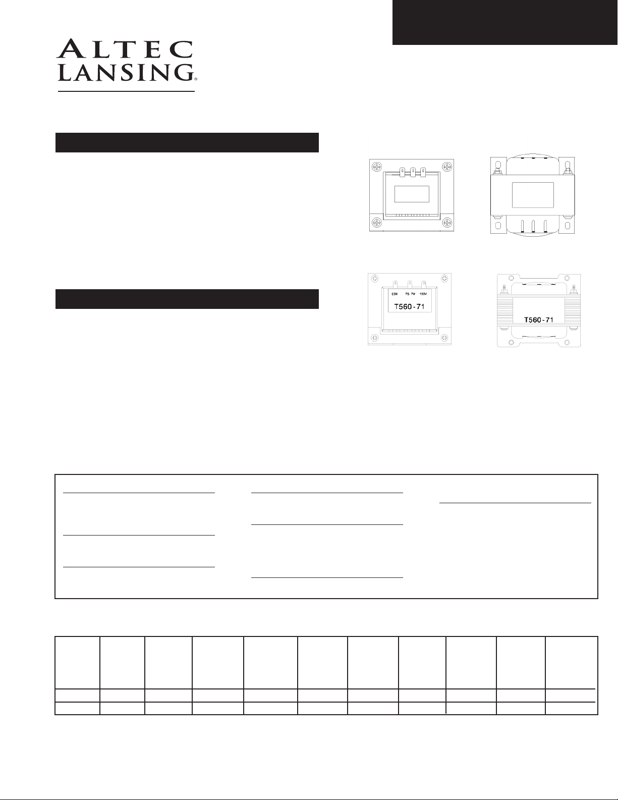
T560-71/T5100-71
70.7 / 100V
Transformers
Altec Lansing is renowned for its high quality transformers.
The new Altec Lansing Professional transformers, T560-71
and T5100-71, are perfect complements to our premium
Duplex® Speakers when the prerequisite is high fidelity.
These transformers are designed for 70.7V or 100V distribution
of amplifier power, with minimal loss, to multiple loudspeakers.
True electrical isolation is provided to the source and the load
by the primary and secondary windings respectively. Installation
is simple with 0.25-inch blade type wire terminals, allowing
either solder connections or crimp type quick-connect wire
terminals.
specifications
Power Rating:
60 Watts (T560-71);
100 Watts (T5100-71)
Frequency Response:
35 Hz to 15 kHz, ±0.5 dB
To tal Harmonic Distortion:
< 0.5% at Rated Power, from
35 Hz to 15 kHz
Phase Response:
-15º to +35º
Insertion loss:
< 1 dB from 35 Hz to 15 kHz
(typically < 0.5 dB from 35 Hz
to 10 kHz)
Primary Taps:
4 Ω and 8 Ω
Secondary Taps:
70.7V and 100V
Hi-Pot: 500 VAC
Weights & measures
Length Width
T560-71
T5100-71
1000 W. Wilshire Blvd., Suite 362 • Oklahoma City, Oklahoma 73116 • Phone: 1-405-848-3108 • Fax: 1-405-848-3217 • www.altecpro.com
3.75”
Height
3.50”
Hole
Center on
Length
3.39”
Hole
Center on
Width
3.00”
Hole
Dimension
0.25” x 0.35”
Winding
Thickness
4.06”
Core
Thickness
2.00”
Bracket
Thickness
0.063”
Weight
8 lbs.
Page 2

ARCHITECTS & ENGINEERS SPECIFICATION
The transformers shall be Altec Lansing Professional model numbers T560-71 and T5100-71, rated at 60 Watts and 100 Watts, respectively.
Their frequency response shall be 35 Hz to 15,000 Hz, ±0.5 dB. Throughout their 35 Hz to 15,000 Hz bandwidth, at rated power, they shall
produce no more than 0.5% T.H.D., and their insertion loss shall not exceed 1 dB. These transformers shall require no more than 10%
above their rated input power to deliver rated power to the load at 35 Hz. The T560-71 and T5100-71 shall provide true electrical
isolation to the source and to the load. Connection to these transformers shall be through 0.25-inch blade type wire terminals. The
nominal primary taps shall be 4 ohm and 8 ohm, and the nominal secondary taps shall be 70.7V and 100V.round white metal grille.E
voltage ratio
4 Ohm
to 70 V
4 Ohm
to 100 V
8 Ohm
to 70 V
8 Ohm
to 100 V
4/8 term
to 70 V
4/8 term
to 100 V
T560-71
T5100-71
impedance ratio
T560-71
T5100-71
wiring diagram
1:4.5
1:3.5
4 Ohm
to 70 V
1:20.8
1:12.5
100 V
70.7 V
8 Ω
4 Ω
1:6.4
1:5.0
4 Ohm
to 100 V
1:41.7
1:25.0
1:3.2
1:2.5
8 Ohm
to 70 V
1:10.4
1:6.3
1:4.6
1:3.5
8 Ohm
to 100 V
1:20.8
1:12.5
1:10.9
1:8.5
4/8 term
to 70 V
1:21.9
1:13.1
1:15.4
1:12.0
4/8 term
to 100 V
1:44.0
1:27.0
E5475 REV01
COMMONCOMMON
P ROFESSIONAl
© 2002 Altec Lansing Professional
1000 W. Wilshire Blvd., Suite 362
Oklahoma City, Oklahoma 73116
Phone: 1-405-848-3108 • Fax: 1-405-848-3217
Web: www.altecpro.com • Email: proinfo@alteclansing.com
 Loading...