

Page 1
SM1
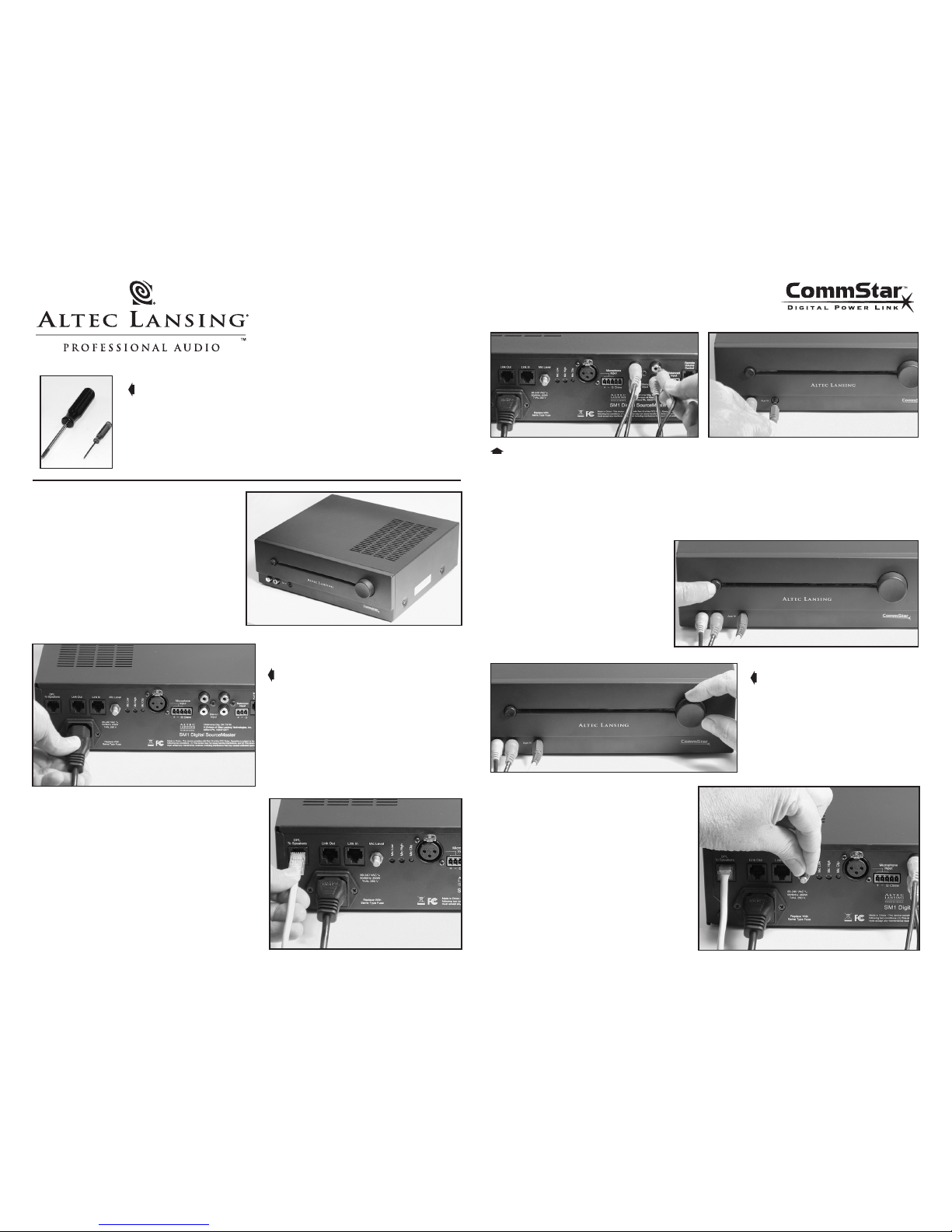
INSTALLATION
GUIDE
STEP ONE ➧
Determine appropriate location for unit.
NOTE: The SM1 requires a minimum of 11 in.
(280 mm) depth, 9.625 in. (245 mm) width, and
3.25 in. (83 mm) height. Space must be provided
both above and below the unit for proper ventilation. The feet will provide 0.2 in. (5 mm) below
the unit. At least 1.75 in. (45 mm) is recommended above the unit.
STEP TWO
NOTE: Verify that the unit’s power switch is
in the off (out) position.
Using the included power cord, connect unit to an appropriate power
source (85-240 VAC, 50/60 Hz).
STEP THREE ➧
Plug CommStar speaker system into the unit’s
DPL To Speakers connector.
NOTE : A maximum of 8 sp eakers can be co nnec ted
to each power sou rce unit . Use only sta ndard wiring
CAT5E cable (no crossover wiri ng) , rated V W-1. Fo r
DPL connecto r pin assignment , see CommStar Tech
Notes, Figure 2.
TOOLS RECOMMENDED FOR INSTALLATION
• A #2 cross-tip screwdriver
(or a powered screwdriver with a #2 cross-tip bit – not shown).
• A mini standard blade screwdriver
STEP FOUR
Connect audio outputs from CD players, Satellite Radio, DVD players, portable music
players, etc. to the RCA inputs on the back panel and/or front panel of the unit
(and/or the stereo mini-jack on the unit’s front panel).
NOTE: As viewed from the back, the leftmost, vertical, red-white RCA pair can accept a higher audio
level than the unit’s other RCA or stereo mini-jack inputs.
STEP FIVE ➧
Depress the front panel power
switch until it clicks, turning the
unit on.
STEP SIX
Adjust front panel control for the
desired music level.
NOTE: It may be necessary to adjust
source to match levels.
STEP SEVEN ➧
NOTE: If not connecting a microphone directly
to the unit, skip to Step Twelve.
Verify that the back panel Microphone
Level control is fully counter-clockwise
(minimum level).
Page 2

STEP EIGHT ➧
Using either the XLR (large photo) or
the euro-block (inset photo) Microphone
Input connectors, plug in the desired
paging microphone.
NOTE: If pre-announcement alert tone is
required, connect switch to the two Chime
terminals of the euro-block Microphone Input
connector. If using a condenser microphone
that requires Phantom Power, see CommStar
Tech Notes Figure 1, Phantom Power Supply
section.
STEP NINE
With the back panel Microphone Level
control fully counter-clockwise (minimum
level), speak forcefully into the paging
microphone and verify that the
Mic Clip
LED is off (or rarely turns on).
NOTE: If the Mic Clip LED is on frequently, internal
gain reduction may be required (CommStar Tech
Notes Figure 1, Microphone Preamp Gain section).
STEP TEN ➧
Still speaking forcefully into the
paging microphone, rotate the rear
panel Microphone Level control
clockwise until the desired paging
output level is achieved from the
sound system.
NOTE: If attenuation of music during a page is
not desired, see CommStar Tech Notes Figure 1,
Background Music Attenuation section.
Mic Clip LED
STEP ELEVEN
Speaking normally into the
paging microphone, adjust the
Microphone’s Low frequency
(large photo) and High frequen
cy (inset photo) controls for the
desired voice contour or timbre.
STEP TWELVE ➧
If using a professional mixer, connect its mono analog output to the
euroblock Balanced line Input
.
NOTE: If m usic- enhan ced signa l pro cessing i s des ired for t he Balanc ed In put, see
CommS tar Tech Note s Figure 1, Ba lance d
Input Sign al Pr ocess ing secti on.
OPTION 1
Use this unit’s Link In jack to connect
a professional mixer (or other source)
with an AES/EBU output. For Link In
details, see CommStar Tech Notes, Figure 5.
NOTE: The last speaker of one CommStar
system may be connected to the Link In
jack of another SM1 (or a C1), allowing for
system expansion.
OPTION 2 ➧
Other systems with an AES/EBU input may be connected to this unit’s
Link Out jack. For Link Out connector
pin assignment, see CommStar Tech Notes,
Figure 4.
NOTE: This unit’s Link Out may be connected to the Link In of another SM1 (or a
C1), allowing for system expansion.
OPTION 3
If remote volume control is required, only use CommStar model
RVC, and connect it to the unit’s
Remote Volume Control
jack.
For Remote Volume Control connector pin assignment, see CommStar Tech
Notes, Figure 3.
© 2006 Altec Lansing Professional • 1000 W. Wilshire Blvd., Suite 362 • Oklahoma City, Oklahoma 73116 • Phone: 1.405.848.3108 • Fax: 1.405.848.3217 • Email: proinfo@alteclansing.com
APXXXX R01
 Loading...