

Page 1
HIGH ACOUSTIC OUTPUT
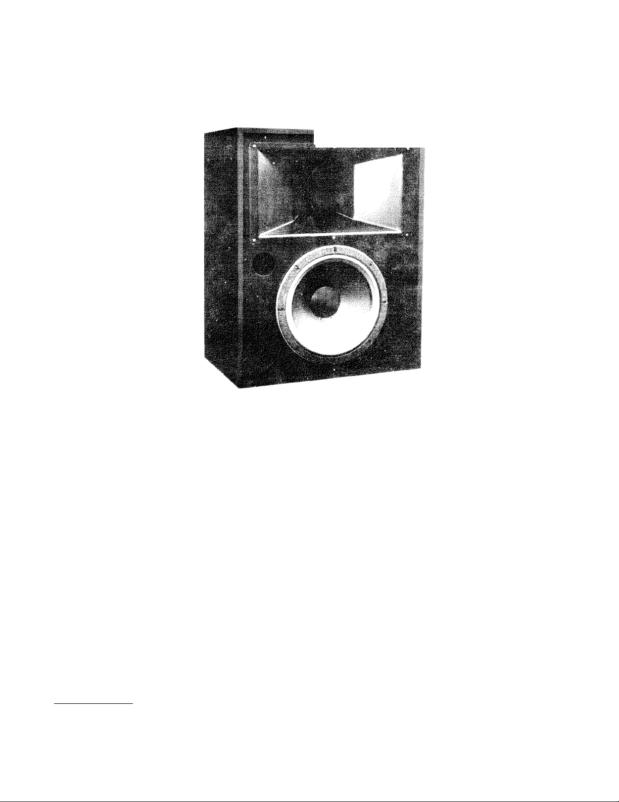
M500 Maestro Monitor - High Output Performance!
HIGH ACOUSTIC OUTPUT 250 WATT
FRONT MOUNTED COMPONENTS
RUGGED PASSIVE CROSSOVER
TWO-WAY VENTED SYSTEM
16" DIRECT RADIATOR
909 DRIVER AND HORN
T’-NUT SUSPENSION
APPLICATIONS
• Music Playback in Conference Facilities
• Small Dance Environments
• Simple Cluster in Houses of Worship
Page 2
SPECIFICATIONS FOR THE M500 MAESTRO MONITOR TWO-WAY SYSTEM
System Type:
Pressure Sensitivity:
Frequency Response:
Power Handling:
Maximum Long-Term
Output:
Impedance:
Distribution Pattern:
Components:
Crossover Network:
Two-way, vented, full range
loudspeaker system.
96.5 dB SPL (1W, 500 Hz - 3kHz,
re: 20/tPa, see Note 1)
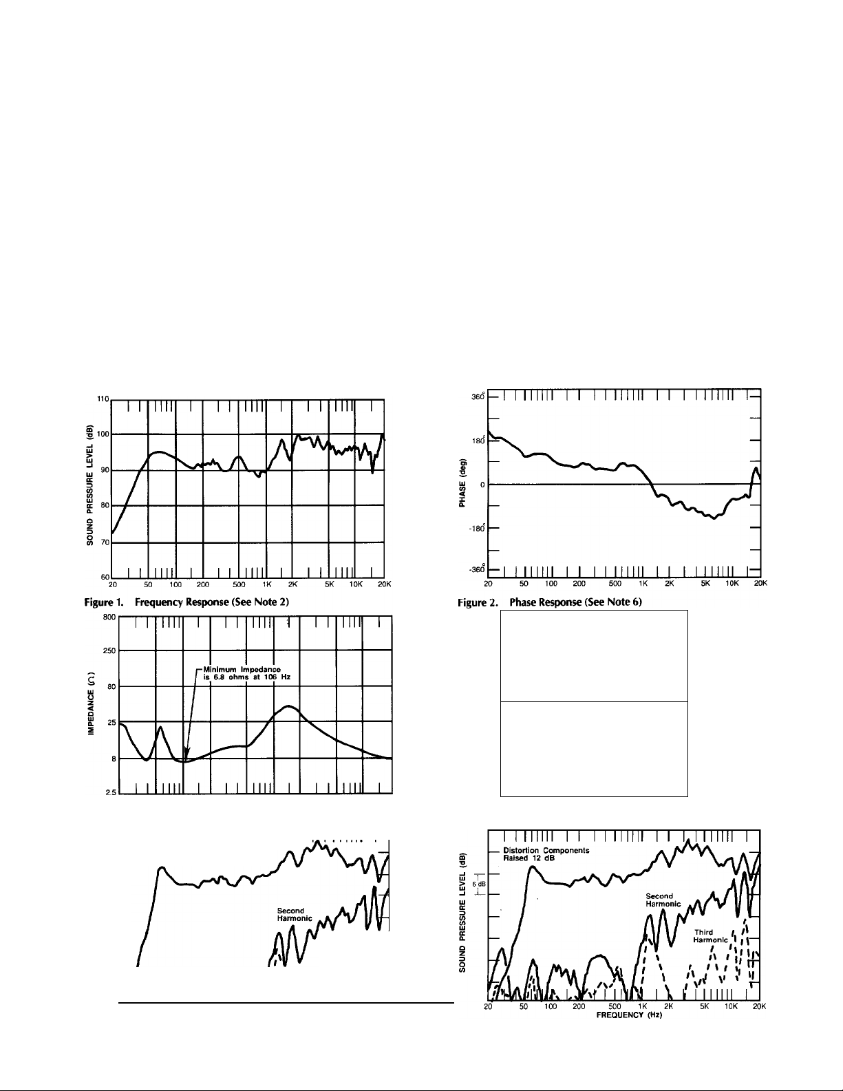
46 Hz - 20 kHz (see Figure 1,
Note 2)
250 watts, 80 Hz-20 kHz, AES method
(see Note 3)
120.5 dB SPL (250 watts input, 1 m,
re: 20/jPa, see Note 4)
6.8 ohms minimum, maximum
inductive phase angle = 39° @ 1028
Hz, maximum capacitive phase
angle = 41 ° @ 9 Hz, (see Figures 3 and
4, Note 5)
90° horizontally x 40° vertically
(see Figure 8).
Model 3154 low frequency loud
speaker, model 909-8A high frequency
driver, model MR994A Mantaray® high
frequency horn.
Part number 56-06-027908, at 630 Hz,
with choice of high frequency
attenuation.
Enclosure:
Input Connection:
Replacement H.F.
Diaphragm:
Replacement L.F.
Recone Kit:
Replacement Grille:
Dimensions:
Net Weight:
Shipping Weight:
Finish:
Vented type for optimum response,
built of (1.9 cm) black stained
birch plywood (unfinished veneer
model; 9815-8A) with appropriate
bracing and stiffeners, lined with glass
wool, including Vie" tee-nut mounting
points on each side and a removable
grille.
Red and black five-way binding posts.
Model 26420
Model R3154
RC-M500
33" (83.8 cm) high
261/2" (67.3 cm) wide
171/2" (44.5 cm) deep
86 lbs. (39.1 kg)
98 lbs. (44.5 kg)
Black stained birch veneer (M500)
and unfinished birch veneer (9815-8A),
black grille cloth.
50 100 200
Figure 3. Magnitude of Impedance
Distortion Components
Raised 18 dB
j
__
i/\I iAi/SAiiuK\l\ \\ A/fMvii'*r
20 50 100 200 500 IK 2K 5K 1
Figure 5. Harmonic Distortion at 0.01 Rated Power
(2.5 watts, See Note 7)
500 IK 2K
FREQUENCY (Hz)
I I I m i l l I I
FREQUENCY (Hz)
5K 10K 20K
Third / ;•
Harmonic/lf I
III» I,
»X
. 30 -
---------1--------
I 20 -
г--------1
--------1-------
A. Maximum Inductive
Phase Angle is
39° at 1028 Hz
A
1--------
C ? 10
u
<
Ш
IC
10
-
20
_____I_____
30
10 20 30
Figure 4. Complex Impedance
Figure 6. Harmonic Distortion at 0.1 Rated Power
(25 watts, See Note 7)
B. Maximum Capacitive
i 1 i
L
Phase Angie is
41° at 9 Hz
50 60
-
Page 3

BO® 270®
BO® 270'
M® 270'
315 Hz
800 Hz
2000 Hz
400 Hz
8000 Hz
20000 Hz
BO® 270'
10000 Hz
Figure 7. One-third Octave Polar
Response Charts
(See Note 8)
5000 Hz
12500 Hz
HORIZONTAL-
VERTICAL-
SCALE IS 5 dB/div.
6300 Hz
16000 Hz
Page 4

6
5
lU
c
S
31.5 63 125 250 500 1K 2K 4K 8K 16K
FREQUENCY (Hz)
Figure 8. Coverage Angle
31.5 63 125 250 500 IK 2K 4K 8K 16K
FREQUENCY (Hz)
Figure 10. Horizontal Off-Axis Response Contours
DISTANCE (m)
31.5 63 125 250 500 IK 2K 4K 8K 16K
FREQUENCY (Hz)
Figure 9. Q and Dl
FREQUENCY (Hz)
Figure 11. Vertical Off-Axis Response Contours
10000 10631 11663 13326 14157
TIME (JJS)
Figure 12. Energy Time Curve (See Note 9)
Page 5

NOTES ON MEASUREMENT CONDITIONS
1. Pink noise signal, one Watt calculated using
E'2/Zmin, 3.16 meter measurement distance
referred to one meter.
2. On-axis, one Watt calculated using E''2/Zmin,
3.16 meter measurement distance referred to
one meter, low frequencies corrected for
anechoic chamber error.
3. This system rating patterned after the AES
method for individual driver, where the test
signal is pink noise with 6dB crest factor over
the bandwidth of the system, with power cal
culated using E*2/Zmin, for two hours.
4. This measurement made under the same con
ditions as Pressure Sensitivity, but at rated
power, and takes into account any power
compression effects due to non-linearities in
the system.
5. The loudspeaker system should be connected
to the 8-Ohm tap on amplifiers using trans
former coupled output sections.
6. Phase response of the system is measured at
a time corresponding to the energy arrival of
the high frequency component where the
amplitude response is optimally flat, as noted
on figure 12.
7. Distortion components invalid above 10 kHz.
The distortion at any given frequency may be
found by graphically taking the difference
between the fundamental and harmonic,
adding the number of Decibels which the
harmonic has been raised on the graph and
apply the formula:
percent distortion = 100 X 10"
(-dB change/20)
8. The axis of rotation for all polar plots is the
apparent apex of the high frequency driver.
Plots below 200 Hz have not been shown be
cause of their lack of pertinent information.
9. The time window has been chosen to resolve
the arrival times of the low and high frequency
components. Frequency bandwidth of the
measurement, 0 Hz - 20 kHz.
10. Response decay of the system. Time window
is selected to display loudspeaker and box
characteristics without room reflections.
5/16-18 FORGED
EYE BOLT
Figure 14.
5/16-18 HEX NUT-
CENTER OF GRAVITY
A = 16 in. (34.3cm.)
B = 8 3/4 in. (19.0cm.)
FLAT WASHER
LOUDSPEAKER SYSTEM IS SHOWN SUSPENDED WITH
LOW FREQUENCY DRIVER TOWARD THE BOTTOM.
Page 6

63.5cm.
,T"
10.2cm.
25"
4”—
10.2cm
<)
-9-
-------
I
■ 17.5” -
44.5cm.
9.5”
24.1cm.
LOUDSPEAKER SYSTEM IS SHOWN WITH LOW
FREQUENCY DRIVER TOWARD THE BOTTOM
Figure 15.
ARCHITECT'S AND ENGINEER'S SPECIFICATIONS
The loudspeaker shall be the Altec Lansing Maestro
Series M500. It shall be of the two-way bass reflex
type, consistingof a front mounted 16-inch (40.6
cm) low-frequency loudspeaker, a high-frequency
compression driver on an injection molded con
stant directivity horn, and a dividing network
having a crossover frequency of 630 Hz. The
loudspeaker system shall meet the following per
formance criteria: Power handling, 250 watts of
pink noise with 6 dB crest factor, band width
limited from 48 Hz to 20 kHz. Frequency response,
smooth and uniformly usable at high levels from
48 Hz to 20 kHz. Pressure sensitivity, 96.5 db SPL
at one watt, 500 Hz to 3 kHz, measured at a
distance of one meter on axis. Impedance, 8 ohms
nominal, 6.8 ohms minimum. Distribution pattern
90° horizontally nominal from 2 kHz to 20 kHz
X 40° vertical nominal from 2 kHz to 20 kHz
with asymmetrical coverage in the vertical plane.
The enclosure shall be constructed of braced
3/4-inch (1.9 cm) birch plywood damped with
sound absorbing glass wool. The M500 shall
have a black stained finish. The dimensions shall
be 33 inches high by 26V2 inches wide by 171/2
inches deep (83.8 cm high x 67.3 cm wide x
44.5 cm deep). The loudspeaker system shall
weigh 86 lbs. (39.1 kg).
RO. BOX 26105 • OKLAHOMA CITY, OK • 73126-0105 U.S.A. • 405/324-5311 OR FAX: 405/324-8981
PRINTED IN U.S.A. 8/90
LANSING*
a MARK IV company
©1990 ALTEC LANSING CORPORATION
AL-1602 42-02-027992
 Loading...