

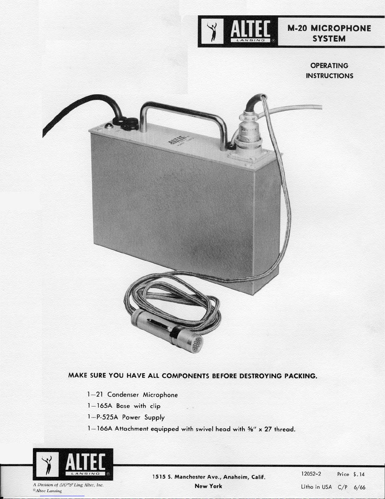
Page 1
Page 2
SPECIFICATIONS
Frequency Response: See curve.
Output Level with various loads:
Unbalanced—High impedance (10,000 ohms or higher)—
30 db re 1 V. 10 dynes/cm-600 ohms—49 dbm re 10
dynes/cm-150 ohms—53 dbm re 10 dynes/cm-30 ohms—
59 dbm re 10 dynes/cm-Balanced—(Using 4665 plug-in
transformer)
600, 150 or 30 ohms—48 dbm re 10 dynes/cm-Power
Requirements: 117 V., 60 cycles, 15 watts Physical: P-525A
Power Supply—width 85/8", height 23/8", depth 71/2".
Finish—21 microphone, stainless steel; 165A base—
gray anodize; P-525A Power Supply—silver gray
cover with gray anodized panel.
Mounting—166A holder attachment threaded 5/8"—27
to mate with 22C floor or 24C desk stand or other
standard microphone stand. Weight—M-20 System
(unpacked)—6 lbs., 1 1 oz.
Accessories: 4665 plug-in transformer for balanced output line.
167A extension cable 25 ft. long equipped with
Cannon RWK 6-22C and RWK 6-21C cable con-
nectors.
22C floor stand, adjustable 35" to 64".
24C desk stand.
11853 rack mounting assembly for two P-525
power supplies, 31/2 inches high x 19 inches
wide x 71/2 inches deep.
168A or 170B wind screen
169A shock mount
OPERATION
The "Lipstik" microphone system is designed to work with any existing microphone preamplifier or facility regardless of the input
impedance. Aside from the outstanding advantages of this microphone, it differs from the conventional only in that the P-525A
power supply must be connected between microphone and amplifier. The 165A base, containing the 5840 vacuum tube and 21
microphone, is terminated at the end of a 15' cable in a Cannon connector which in turn mates with its companion fitting on the
panel of the P-525A power supply. Extension cables may be used as described below. The output appears at the end of the 2conductor shielded cable extending from the power supply. The power supply must be energized from the 117 VAC 50-60 cps supply. The 166A holder will snugly grip the 165A base providing a light streamlined swivel attachment for floor or desk stand. Its
modern line is achieved with ruggedness by combining a molded, high impact Styrene part with a satin chrome die cast swivel,
containing the standard RTMA 5/8—27 thread. A jumbo size fountain pen clip provided, will allow the microphone to be attached
to the lapel affording great freedom of action to the user.
OUTPUT CONNECTIONS
Unbalanced: As supplied, the P-525A power supply is equipped with an internal shorting plug which connects the output cable to the
cathode follower, through isolating resistor and condenser. This condition is preferred when the following amplifier has a high impedance or unbalanced (transformerless) input. It may also be operated into amplifiers having low impedance input connections where
line balance is not of importance and a small reduction of sensitivity can be tolerated. An instance of this operation would be a
portable P.A. application in which microphone lines of limited length are used. When the plug is inserted, the black wire of the
output cable is ground, thus is common with the shield.
Balanced: Broadcast and recording applications normally require balanced or at least ungrounded signal lines in the interest of
suppression of unwanted longitudinal signal currents and in maintaining the highest possible signal to noise ratio. This feature is
provided by means of a plug-in transformer (4665) which may be inserted in the P-525A power supply (installation instructions are
given under P-525A power supply). The socket into which the transformer is inserted is strapped to provide a load impedance of
150 ohms. Other load impedances of 30 and 600 ohms may be obtained by re-strapping the socket as indicated on the transformer
schematic. Because of the great latitude in loading permitted by the cathode follower, it is suggested that all load impedances between 30 and 250 ohms be fed from the P-525A without modification of the transformer socket strapping.
Termination: When the 4665 balancing transformer is used, no termination other than that provided by the input transformer of the
following amplifier is required. The unbalanced output (no 4665 transformer) requires termination when working into transformer
loads of 600 ohms or less. A 1/2 watt resistor matching the transformer impedance within ± 20% should be connected across the
power supply output. This is most easily accomplished by installing the resistor in the power supply connector which will plug into
the amplifier.
Sensitivity: The voltage developed at the grid of the first tube following the P-525A power supply, for a given microphone signal
input, will be identical for all balanced line impedances where the amplifier input is matched, using the 4665 transformer. It will
have the same value when the unbalanced (direct cathode follower) output is fed into the first tube of an amplifier not having an
input transformer. However, when the unbalanced output is fed into low impedance transformers and loaded with a resistor as described under Termination, the sensitivity will vary depending upon the load impedance. With a 600 ohm resistor termination working into a 600 ohm transformer, the voltage will be comparable to the above; with a 150 ohm resistor and 150 ohm transformer,
the voltage will be 4 db lower and with a 30 ohm resistor and 30 ohm transformer, the voltage will be 10 db lower. These sensitivities are listed in the specifications relative to microphone inputs of 10 dynes/cm-.
Extension Cable: The cable length supplied between microphone base and Cannon connector is 15 feet. Heavy duty, 25' extension
cables are available as listed, or single lengths of Suprenant 5426 or equivalent six-conductor cable may be utilized to separate
microphone base and power supply up to 400 feet. Belond 400 feet, large conductors should be used for the heater leads to avoid
excessive voltage drop.
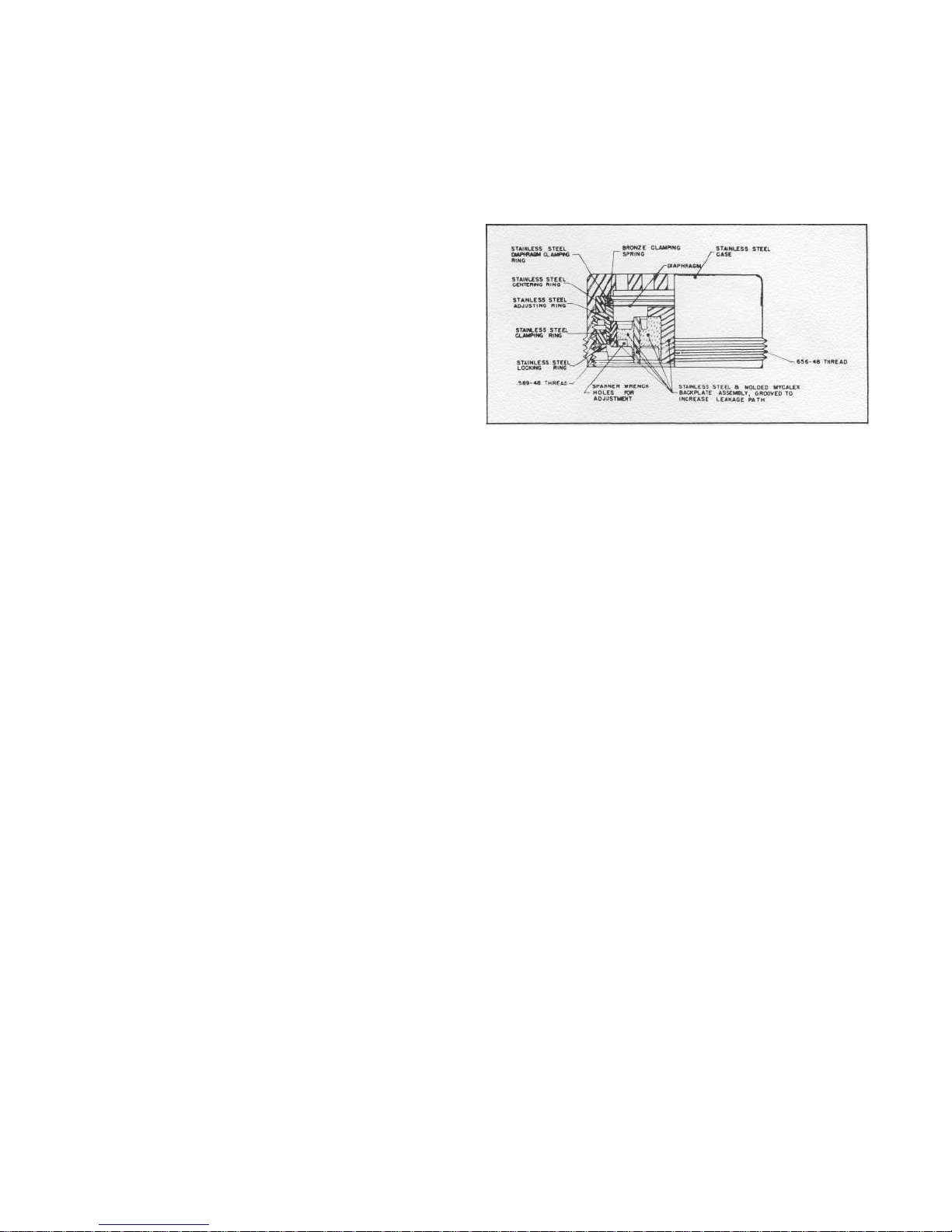
21 Microphone (Fig. 1): The condenser microphone depends for its operation upon variations in its electrical capacitance caused
by microscopic deflections of the diaphragm to a fixed electrode, when exposed to the pressure varations of a sound wave. The
capacitance variation is converted to electrical signal by supplying a polarizing potential to the microphone through an extremely
high resistance. In this case, the potential is 200 volts and the charging resistance is the insulation resistance of the associated vacuum
tube and socket. Since the voltage e across the condenser is proportional to the charge Q divided by the capacitance c, it will decrease for a positive pressure applied to the diaphragm and increase for a negative applied pressure. Thus, the output is proportional to the diaphragm displacement for all frequencies above those at which the microphone reactance, 1/wc, is commensurate
with the leakage resistance. The capacitance of the condenser is approximately 6 mmf. Because of this high internal impedance, it is
necessary to place the cathode follower tube, which serves as an impedance transformer, in close proximity to the microphone.
Page 3

170B WINDSCREEN .. .The 170B windscreen has been developed for the M-20 and M-30 Altec microphone systems and is extremely
effective in wind noise reduction and "Pop" elimination. The 170B windscreen will attenuate wind noise approximately 24 db
without deteriorating the HF response, or discrimination in the case of the AA-30 usage. An exploded view, Fig. 1, is shown to aid
in the installation of the 170B windscreen. Remove the condenser microphone from its base by unscrewing it counter-clockwise.
Caution: The microphone unit 29B or 21D is a precision element and extreme care should be exercised
in handling. Under no circumstances permit anything to touch the contact end of the microphone
— the end unscrewed from the base — as this could result in damage to the microphone unit.
Slip the split ferrule over the base with the split end toward the cord on the base. Replace the condenser microphone in the
base, inside the ferrule. The windscreen may now be slid over the condenser microphone and onto the ferrule until it 'bottoms.' It
will be noted that the ferrule is split to provide tension on the windscreen and holds it firmly in place regardless of the position of
the microphone and still allows it to be used with any base or stand accessory. If, for any reason, it should be desired to operate
either the M-20 or M-30 Altec microphone system without the 170B windscreen (after it has been installed), it may be removed
without detaching the split ferrule.
The "Pop," or explosive sound produced by most people when pronouncing the letter "P" and sometimes "B" in certain words,
is effectively reduced with the 170B windscreen and therefore greatly increases the ease of close proximity work.
165A Base: The base performs the multiple purpose of mounting the microphone, housing the tube, and enclosing the cable connections to the tube. The inner structure of this assembly employs a printed circuit phenolic sleeve which supports the tube socket, providing solder terminating areas for cable wires and tube socket tabs, as well as providing the interconnecting wiring between socket
and cable. The gold plated contact pin at the apex of the assembly is supported by a phenolic bearing cemented into the center
hole of the socket and is connected to the grid by means of the compression spring which surrounds the pin. The cable clamp assembly consists of a special "O" ring, a brass washer, the anodized aluminum clamping nut which completes the case contour, and a
gold plated brass part which supports the printed circuit sleeve and provides threads for mating the outer shell with the clamping
nut. The cable shield and ground wire solder to the brass part and complete the connection to the microphone case through the
outer aluminum shell. The 15' foot length of Tensolite 1883-H6 cable which is part of the base is a six-conductor shielded wire of
small diameter and good flexibility, having an overall jacket of woven fiberglass material providing excellent abrasion resistance.
P-525A Power Supply: This unit, by means of a transformer, dry disk rectifiers and filters, supplies direct current potentials for
operation of the 5840 cathode follower tube and condenser microphone in the 165A base. The circuits are conventional and the
location of components are shown in the accompanying photographs. The shorting plug indicated must be removed when the line
balancing transformer is used. When the transformer is inserted in the socket, it will be seen that two holes in the chassis line up
with threaded inserts in the transformer (plug end). It is recommended that the transformer be secured to the chassis using the two
screws furnished.
Service Data: Caution: when removing the cover from the P-525A power supply or the outer shell from the 165A base, disconnect
the power supply from the power line. The metal condenser cans in the power supply are at a positive potential to ground and
require approximately two minutes to lose the charge after the system is disconnected. If the system fails to operate and the pilot
lamp does not glow, check power line connection and fuse located inside of chassis. If system operates but produces loud hum
when the base or microphone is touched, it is an indication of a poor ground connection between the microphone case and the
cable end of the assembly. To correct, tighten microphone and shell.
If the system is inoperative, but the power supply is producing normal heater and B supply voltages, the potential across R4 should
be measured. R4 is the cathode load resistor for the 5840 tube in the 165A base. With the base disconnected from the power
supply, no potential should exist. With the base connected and the microphone button either on or off of the base, the potential
across R4 should be a nominal 200 volts. If this potential is not obtained, the 5840 vacuum tube is faulty or a cable short or open
exists. If the 200 volts is obtained with the microphone button removed from the base, but not when it. is connected; the microphone
backplate has accumulated moisture. This sometimes occurs when the microphone has been stored in atmospheres approaching
100% humidity. The condition will sometimes correct itself in a short time due to the heating effect of the vacuum tube. If not, the
microphone button can be removed from the base and placed in a ventilated 200° F. oven for a period of seven hours. There will
be no harmful effects so long as the temperature does not inadvertently exceed 600° F.
The shell of the 165A base may be easily removed for inspection by holding firmly the knurled cable clamp nut and unscrewing
the upper shell and microphone. It is recommended that the microphone not be removed from the base unless absolutely necessary.
When it is removed, fingers and dirt should be kept away from the back plate surface and the breath, which contains moisture,
should not be used to blow the assembly clean. The 5840 vacuum tube is a premium type designed for dependable performance
under conditions of shock and vibration. Because of its rugged construction, it should provide extreme service life unless subjected
to drastic abuse. It may be removed from its socket by grasping the two sides of the envelope with the fingers, through the openings in the phenolic sleeve, and rocking gently while withdrawing. When free, the tip end should be depressed into the sleeve until
the pins clear the socket allowing it to be tilted out the larger opening in the sleeve. When re-inserting the tube, the same procedure
should be used, entering the tip end of the sleeve first and depressing until the pins clear the opening, allowing alignment with the
socket. When the shell is removed from the base, extreme care should be exercised to protect the spring loaded contact pin at the
apex of the assembly from damage. Before reassembling, the vinyl insulator surrounding the soldered tube socket connections should
be checked, as this is the only insulator between this point and the outer shell. The cable attached to the base may be replaced in
the field, if necessary, the cable clamp is released by holding the upper gold plated brass part by means of a length of 1/8 inch
diameter drill rod entered in the radially located hole and unscrewing the knurled nut using pliers w ith padded jaws. Connections
to the printed circuit may be soldered using a minimum of heat and preferably using low temperature solder intended for the purpose such as National Lead Co. No. 604-AG. When reassembling the clamp, the 1/8" diameter drill rod serves also as a gauge, the
knurled aluminum nut being tightened until it touches the rod.
Page 4

 Loading...