

Page 1
KEY FEATURES
it Compact Size
it Versatile Mounting Provisions
it Low-Flux-Leakage Magnet Design
it Extended Bass Response
it 70 / 100 Volt Transformer
Version Available
Ml 00 / Ml OOT
Weather Resistant
Compact Loudspeaker System
PRIMARY SPECIFICATIONS
Frequency Response:
Usable Low-Frequency
Limit:
Long-Term Average
Power Handling:
MlOO
MIOOT
Sound Pressure Level
Dispersion Angle:
Directivity Factor:
Re(Q)
Directivity Index:
Di:
85-20,000 Hz, ± 3 dB,
1 Meter on Axis, Swept
1/3-Octave, Anechoic
Environment.
65 Hz, (10-dB-down point)
Capacity per EIA Standard
RS-426A
160 watts.
1 to 30 watts in 3 dB steps.
85 dB at 1 Meter, 1 Watt
Input, Anechoic Environ
ment, Band-Limited Pink
Noise Signal, 300 to
2,000 Hz.
100° ± 25° Horiz. and Vert.,
1.500- 10,000 Hz. Included
by 6-dB-Down Points on
Polar Responses, Indicated
One-Third-Octave Bands of
Pink Noise.
Median: 9.5 (-Fl 3.4,-5.4),
1.500- 20,000 Hz
Median: 9.8 dB (-1-3.8 dB,
-3.6 dB), 2,000-20,000 Hz
DESCRIPTION
The Altec Lansing MlOO and MIOOT are extremely
compact high-performance monitor loudspeaker sys
tems. They are ideally suited for indoor or outdoor
applications requiring high-quality sound reproduction.
As a near-field monitor in control rooms or broadcast
studios, or as a foreground or background loudspeaker
in restaurants and clubs, they are the choice of profes
sional users. The MlOO has a 4 ohm impedance and the
Ml OOT includes an internal 70.7 /100 volt transformer for
use in distributed loudspeaker systems. Their high
power handling also makes them suitable for nearfield
monitoring in live performance situations. Threaded
inserts in the cabinet in combination with the optional
mounting hardware provide a flexible mounting system
for virtually any application. The low-frequency section
is a 5Va' direct radiating woofer with a polypropylene
cone installed in an optimally vented high-impact
polystyrene enclosure. This combination produces
extended bciss response with relatively high efficiency
for a small enclosure. The use of plastic materials for
the enclosure and cone allow the loudspeaker system
to be used in high-humidity environments. The high-fre
quency section is a r direct-radiating soft dome tweet
er. The tweeter is ferro-fluid cooled eind uses flexible
tinsel lead wires to prevent thermal or mechanical
failure. These features in addition to the large magnetic
system make this the most rugged tweeter ever used in
a system this size. To prevent loudspeaker failure from
being accidently over-driven, independent woofer and
tweeter protection circuits have been incorporated.
These circuits will automatically reduce the power being
delivered to the drivers if their threshold is exceeded,
greatly reducing the possibility of driver failure. Both
drivers feature low-flux-leakage designs enabling the
speaker to be used in close proximity to video monitors.
For very critical video monitoring applications, a mini
mum distance of four inches from the edge of the
loudspeaker to the edge of the CRT is recommended.
Page 2
Ml 00 / M100T Specifications (continued)
Transducer Complement,
High-Frequency:
Low-Frequency:
Box Tuning Frequency:
Crossover Frequency:
Ml00 Impedance,
Nominal:
Minimum:
Enclosure Materials:
Replacement Parts
MIOO/MIOOT,
Woofer:
Tweeter:
Grille:
MlOO,
Network:
MIOOT,
Network:
Transformer:
Color: Black
Optional Accessories:
2.5cm (1 inch) Tweeter
13cm (5'/4 inch) Woofer
75 Hz
3,500 Hz
4 ohms
3.7 ohms at 270 Hz
High impact polystyrene
structural foam.
MIOO-RLF
MIOO-RHF
MIOO-RG
MIOO-RNW
MIOOT-RNW
MIOOT-RXFMR
M-IOOMB mounting bracket.
(Order separately)
Dimensions,
Height:
Width:
Depth:
Net Weight:
Shipping Weight:
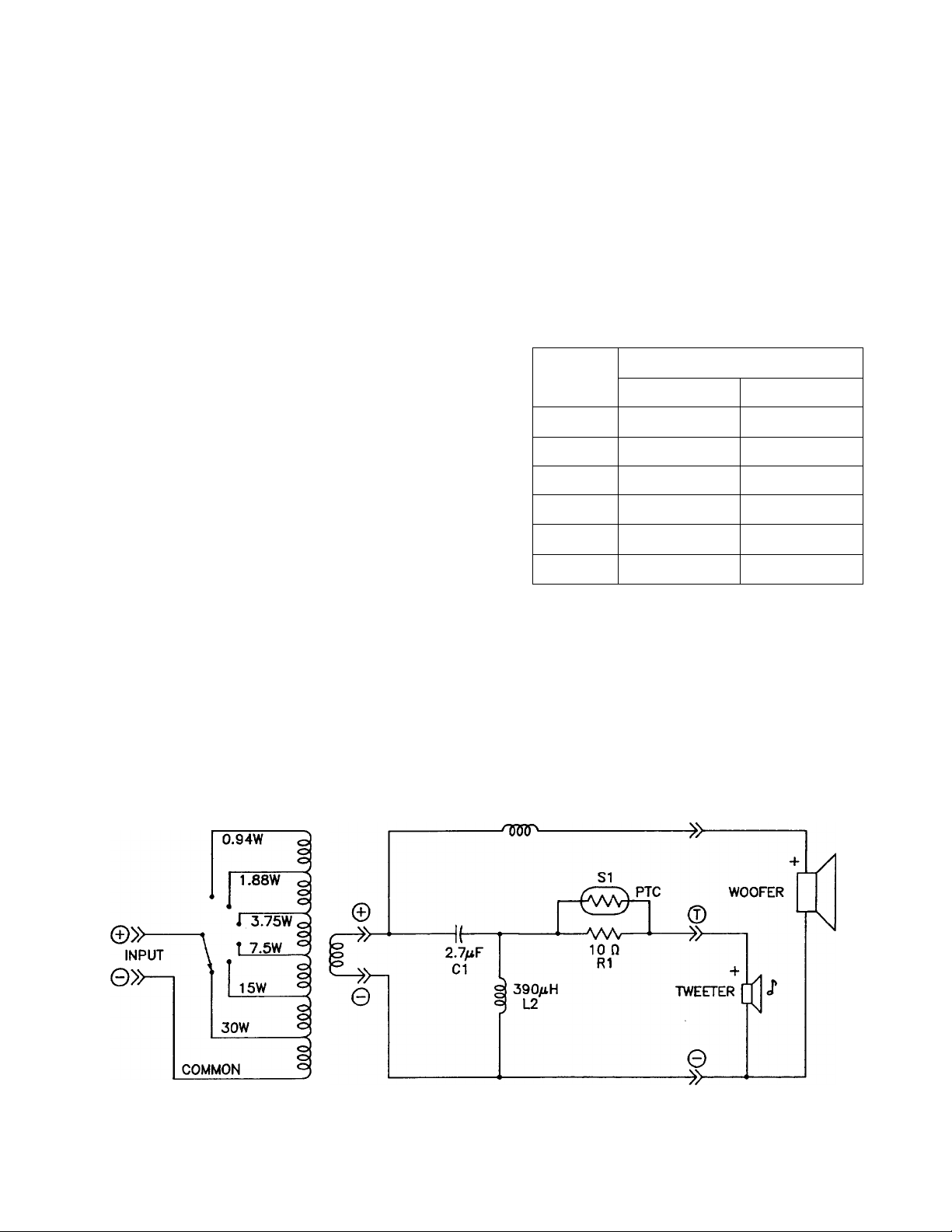
MIOOT Transformer Impedances
Power
Tap
30W 335R 167«
15W 670n 335«
7.5W 1360«
3.7W 2700« 1360«
1.9W 5400« 2700«
0.94W N/A 5400«
24.9 cm (9.8 in.)
17.8 cm (7.0 in.)
15.0 cm (5.9 in.)
2.6 kg (5.7 lb) each
5.7 kg (12.7 lb) per pair.
Impedance
100-Volt 70-Volt
670«
WATTAGE SHOWN
IS FOR 70.7V
LINE.
MIOOT / Ml00 Schematic
LI
I6O/4H
J'cT
Page 3
m 90
o.
to 80
100
to
UJ
liJ
oc
o
UJ
Q —
Z-D
O'
g
s
<
UJ
m
70
FREQUENCY IN HERTZ
FIGURE — 1
Axial Frequency Response
360
300
200
rn 1 ■ ■ 1 11 ■ 1 1nr ■ I 1
A
100
80
60
40
30
20
HORIZONTAL 0
VERTICAL A
100 200 500 1000 2000
FREQUENCY (Hz)
FIGURE —2
Beamwidth vs. Frequency
SOO 1000 2000
HT
Í1 - -
II
___
№
7K
5000 10000 20000
n
¥
210* ^ I _
---------------ISO*
^ 150*
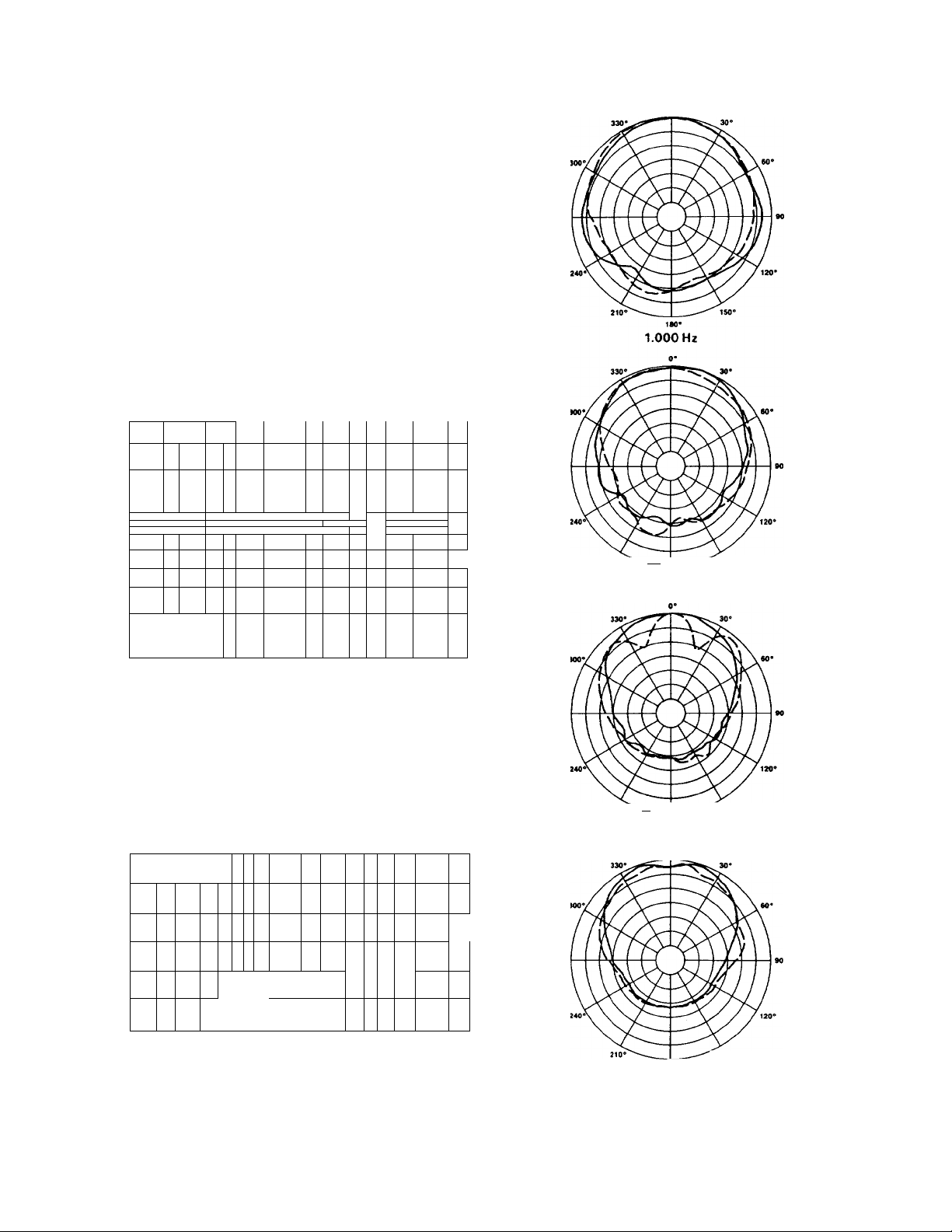
2.000 Hz
210*^--»..^ I_________________150*
ISO*
4.000 Hz
NUMBERS INDICATE
100
10
SPEDFIC R« VALUES
100
<
0 «1
1 C
«
0 «
> o
s
O
yC>> a
1 e
® M* ^ ^
4
to
5"
500 1000 2000 5000 10000 20000
FREQUENCY IN HERTZ
í:
FIGURE — 3
Directivity vs. Frequency
Whole Space (anechoic)
IT ^ ^
g
X
m
o
+ 20 ^
O)
H
: CÍ
> CM
€1
+ 10
-<
z
D
m
X
p
q!
x
____
150*
SO* Horizontal
8,000 Hz Vertical — — —
FIGURE —4
Polar Response
O
•q:
tr
O
Ü
<
u.
>
t
>
h-
Ü
UJ
QC
Q
Page 4
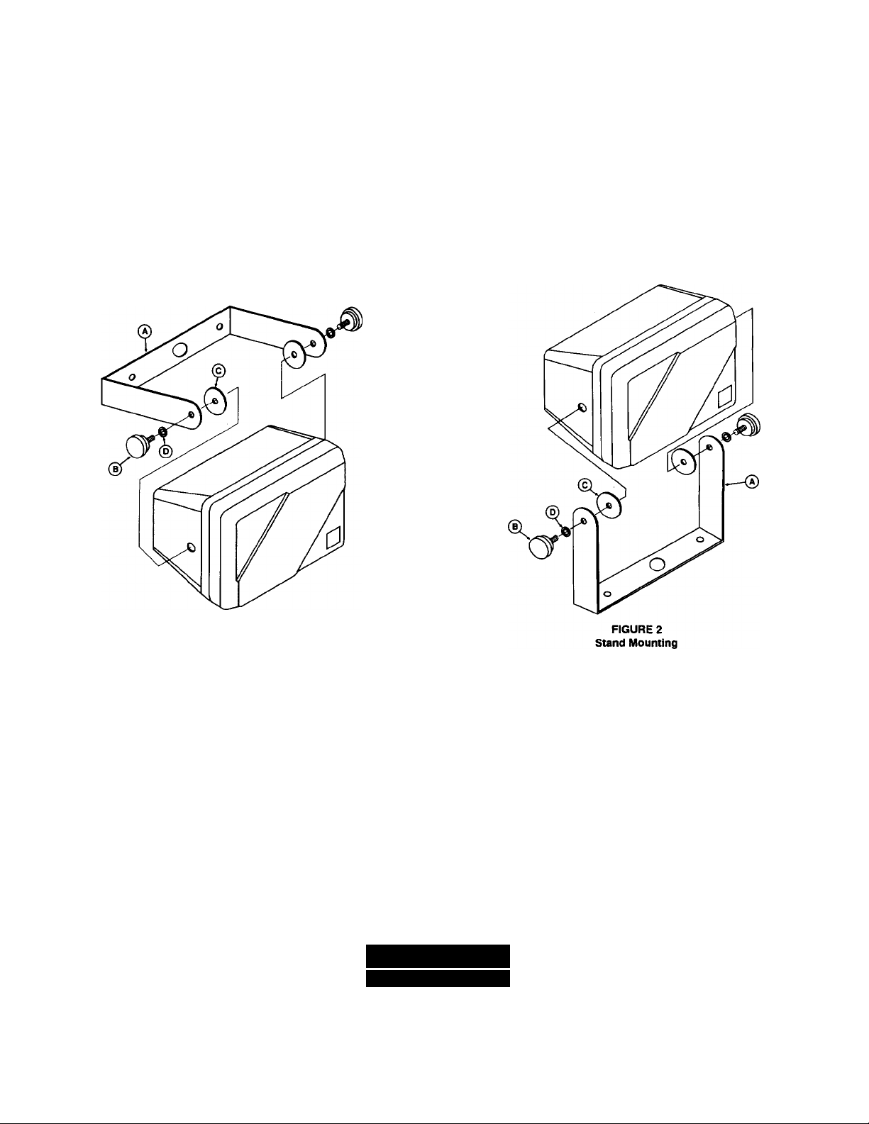
INSTALIATION NOTES
On the back of the Ml00 are two '/4-20" threaded inserts.
These are intended to be used with mounting systems
which have 2-3/8" mounting centers, such as the Omni
mount Systems Series 25. A U-type bracket, the
Ml00MB is also available. This will allow the Ml 00 to be
mounted on walls or ceilings. A microphone stand
adaptor is also included. Complete mounting instmctions are include with the Ml 00MB. Care should be
taken to ensure that the chosen fixing point is strong
enough to support the Ml00. Care should also be taken
to ensure that the Ml00 is not exposed to direct precipi
tation. If the speaker system is not used with one
of the mounting brackets, such as on a bookshelf, then
the rubber feet that are included with the Ml00 should
be attached to the speaker. If the spieaker is placed on
the bottom side, then a mbber foot should be attached
to each of the two rear comers only. This will compen
sate for the 3° draft that is molded into the cabinet, and
allows the baffle to sit perpendicular to the surface that
the speaker is placed on. If the speaker is to be placed
on its side, then a rubber foot should be attached to
each of the four comers. The nameplate that is at
tached to the grille may be rotated depending on which
mounting orientation is used.
FIGURE 1
Wall Mounting
ARCHITECT'S and ENGINEER'S SPECIFICATION
The loudspeaker shall be a two-way system con
sisting of a 13 cm (5% inch) low-frequency loud
speaker, 2.5 cm (1 inch) high-frequency loud
speaker,
[MlGOT only: 30-watt line transformer,]
and frequency dividing network installed in a
vented enclosure. [MIOOTonly: The line transform
er shall have power taps for 30 watts, 15 watts, 7.5
watts, 3.7 watts, 1.9 watts, and 0.94 watts. The
power taps shall be switch selectable.] The divid
ing network crossover frequency shall be 3,500 Hz.
The dividing network shall include a protection cir
cuit for the high-frequency loudspeaker.
ALJTEIO
LAIN!SI INI
P.O. BOX 26105 • OKLAHOMA CITY, OK 73126-0105 • U.S.A. • 405/324-5311 or FAX: 405/324-8981
© 1991 ALTEC LANSING CORPORATION
The loudspeaker system shall meet the following
performance criteria: Power handling, [Ml 00 only:
160 watts,] [MIOOT only: 30 watts.] Frequency
response, ±3 dB from 85 Hz to 20 kHz. Pressure
sensitivity, 84 dB SPL at one watt, 100 Hz to 10 kHz
measured at a distance of one meter on axis. The
enclosure shall be molded of high impact polysty
rene stmctural foam. The unit shall be 24.9 cm
(9.8 inch) high, 17.8 cm (7.0 inch) wide, 16.8 cm
(6.6 inch) deep. The loudspeaker shall be the
Altec Lansing Maestro series MlOO [lOOT].
PRINTED IN U.S.A. 5/91
Revision 1
42-02-037525 42-07-037525 531703
 Loading...