

Page 1

ADA890
User Guide Altec Lansing
Amplified Speaker System
Manuel de l’utilisateur Enceintes amplifiées
Altec Lansing
Manual del usuario Altec Lansing
Sistema de altavoces amplificado
Manuale d’Uso Altec Lansing
Sistema amplificato di altoparlanti
Benutzerhandbuch Altec Lansing
Aktivlautsprecheranlage
© 2000 Altec Lansing Technologies, Inc. Milford, PA 18337
THX and the THX logo are trademarks of Lucasfilm Ltd.
Manufactured under license from Dolby Laboratories.
“Dolby” and the double-D symbol are trademarks of Dolby Laboratories.
A6612
Page 2
The lightning flash with arrowhead, within an equilateral triangle, is
intended to
alert the user to the presence of uninsulated “dangerous voltage”
within the product’s enclosure that may be of sufficient magnitude to
constitute a risk of electric shock
to persons.
Read Instructions — All the safety and operating instructions should be read before the appliance is operated.
Retain Instructions — The operating instructions should be retained for future reference.
Heed Warning — All warnings on the appliance and in the operating instructions should be adhered to.
Follow Instructions — All operating and use instructions should be followed.
Water and Moisture — The appliance should not be used near water – for example, near a bathtub, washbowl, kitchen sink, laundry tub, in a wet basement, or near a
swimming pool, etc.
Outdoor Use — Warning: To reduce the risk of fire or electric shock, do not expose this appliance to rain or moisture.
Location — The appliance should be installed in a stable location.
Ventilation — The appliance should be situated so that its location or position does not interfere with its proper ventilation. For example, the appliance
should not be situated on a bed, sofa, rug, or similar surface that may block the ventilation openings; or placed in a built-in installation, such as a closed bookcase or cabinet
that may impede the flow of air through the ventilation openings.
Heat — The appliance should be situated away from heat sources such as radiators, heat registers, stoves, or other appliances (including amplifiers) that produce heat.
Power Sources — The appliance should be connected to a power supply only of the type described in the operating instructions or as marked on the appliance.The unit
should be installed close to the AC power outlet so that the power plug can be readily removed from the outlet in the event of a hazardous problem.
Power-Cord Protection— Power-supply cords should be routed so that they are not likely to be walked on or pinched by items placed upon or against them. Pay particular
attention to cords at plugs, convenience receptacles, and the point where they exit from the appliance.
Grounding or Polarization — The precautions that should be taken so that the grounding or polarization means of an appliance is not defeated.
Cleaning — The appliance should be cleaned only with a polishing cloth or a soft dry cloth. Never clean with furniture wax, benzine, insecticides or other volatile liquids
since they may corrode the cabinet.
Non-Use Periods — The power cord of the appliance should be unplugged from the outlet when left unused for a long period of time.
Object and Liquid Entry — Care should be taken so that objects do not fall and liquids are not spilled into the enclosure through openings.
Damage Requiring Service — The appliance should be serviced by qualified service personnel when:
• The power-supply cord or the plug has been damaged.
• Objects have fallen, or liquid has been spilled into the appliance.
• The appliance has been exposed to rain.
• The appliance does not appear to operate normally or exhibits a marked change in performance.
• The appliance has been dropped or the enclosure damaged.
Servicing — The user should not attempt to service the appliance. Servicing should be referred to qualified service personnel or returned to the dealer or call the Altec
Lansing service line for assistance.
CAUTION: TO PREVENT THE RISK OF ELECTRIC SHOCK, DO NOT REMOVE COVER
(OR BACK). NO USER- SERVICEABLE PARTS INSIDE. REFER SERVICING TO
QUALIFIED SERVICE PERSONNEL.
The exclamation point within an equilateral triangle is intended to alert
the user to the presence of important operating and maintenance
(servicing) instructions in the literature accompanying the appliance.
SAFETY INSTRUCTIONS
The FCC Wants You to Know
This equipment has been tested and found to comply with the limits for a Class B digital device, pursuant to Part 15 of the FCC rules. These limits are designed to
provide reasonable protection against harmful interference in a residential installation. This equipment generates, uses and can radiate radio frequency energy and, if not
installed and used in accordance with the instructions, may cause harmful interference to radio communications. However, there is no guarantee that interference will
not occur in a particular installation. If this equipment does cause harmful interference to radio or television reception, which can be determined by turning the equipment
off and on, the user is encouraged to try to correct the interference by one or more of the following measures:
a) Reorient or relocate the receiving antenna.
b) Increase the separation between the equipment and receiver.
c) Connect the equipment to an outlet on a circuit different from that to which the receiver is connected.
d) Consult the dealer or an experienced radio/TV technician for help.
FCC Warning
Modifications not expressly approved by the manufacturer could void the user authority to operate the equipment under FCC Rules.
CAUTION
Connecting the Power Cord
AC Wall Socket
Long slot is neutral (ground) side.
Insert the wide blade into the ground
side slot.
To prevent electric shock do not use this (polarized)
plug with an extension cord, receptacle or other outlet
unless the blades can be fully inserted to prevent blade
WARNING
TO REDUCE THE RISK OF FIRE OR ELECTRIC SHOCK, DO
NOT EXPOSE THIS APPLIANCE TO RAIN OR MOISTURE.
Introduction
The ADA890 is a technologically advanced, THX®-Certified multimedia amplified speaker system featuring Dolby Digital and Pro Logic surround sound and stereo
reproduction. Stereo sound can operate in a 2 speaker or 4 speaker configuration (Stereo X 2). Both modes also utilize the subwoofer. The amplifier inputs operate on
analog and digital (S/PDIF)* audio signals. The system also can be used with home Gaming Systems.
The unit is comprised of a subwoofer and two satellite speakers. This combination provides surround sound on a desktop by utilizing side firing speakers. For enhanced
surround sound the top speaker portion of each satellite can be separated and placed on a provided stand with long speaker wires. This enables the separated speakers
to be placed for best surround sound performance. Equalizer circuitry automatically resets to conform to the changes that take place when the speakers are separated.
The satellite speakers are magnetically shielded and can be placed close to a monitor without disturbing images. The speaker in the subwoofer is not magnetically
shielded and should not be placed close to a monitor.
Subwoofer frequencies are non directional, therefore the subwoofer does not have to be located in any particular relationship to the satellite speakers. Placing it on the
floor close to a wall, corner of a room, or under a desk gives excellent results.
The main satellite speaker has an LCD display that shows the various conditions of operation. Amaster volume control is used to separately adjust bass, center, surround,
and treble settings. Once the individual functions are set, the control reverts back to becoming a master volume control. This and other features are explained under
"Using The Speaker System".
A headphone jack is available for private listening. Aremote control unit is supplied that can access all the manual functions. The remote control has a mute function
that is not available when using the controls manually.
An LED POWER INDICATOR and DIAGNOSTIC AUDIO SIGNAL switch are provided for trouble shooting the system in the event a malfunction is suspected.
*Sony/Philips Digital Interconnect Format.
What is THX Certified
THX Certified products must meet an exclusive set of performance standards established by THX Lucasfilm® which is a division of the world-renonwned film
production company, Lucasfilm Ltd. These THX performance standards were originally developed in response to George Lucas’ personal desire to insure that the
original Star Wars™ soundtracks, heard in the cinema, matched those created on the sound stage. Later, these standards were extended to encompass Home Theater
systems and recently adapted to the specialized needs of multi-channel surround reproduction from movies and games, on DVD, played back on a PC-based multimedia
system. All multimedia products seeking THX Certification must meet these rigorous performance requirements and quality standards before they can carry the THX
logo which is your guarantee that this THX certified Multimedia product will give you performance and reliability, second-to-none, for years
to come.
Setup
Do not plug the AC power plug into the wall outlet until all connections are made.
The ADA890 can be setup in two configurations. For ENHANCED SURROUND SOUND a 5-piece setup is used. For near field STEREO/SURROUND SOUND a
3-piece setup is used. The two modes of operation are described below. The speakers are packaged and shipped in the 5-piece arrangement. Follow the instructions
and pictorial in Figure 1 to make the 5-piece connections.
The ADA890 can be used with Gaming Systems such as the Sony PlayStation and with Sega Dreamcast with the analog input as shown in Figure 2. Playback with this
method will result in simulated Dolby® ProLogic surround sound, when in ProLogic mode, for a great gaming experience. ADA890 also can be used with any other
sound system with dual right and left RCA outputs.
For Dolby® Digital sound with the ADA890 and the Sony PlayStation2, there is an optional optical to S/PDIF converter , called OC1, available for sale on the Altec web
site at www.altecmm.com.
Enhanced Surround Sound Operation (See Figure 1)
1) Connect the left and right satellite speakers.
Notice that the DIN connectors from the left and right satellite speakers are color-coded and plug into the matching color indicators on the back of the subwoofer.
Also note that the connectors have arrows. These arrows should face up as shown in figure 1.
2) Connect the left and right surround speakers.
The left (WHITE) and right (PURPLE) surround speaker connectors are plugged into the corresponding colored inputs on the back of the subwoofer.
3) Connect the subwoofer to the computer. (See Note 1)
The lime color-coded wire connects the FRONT INPUT on the subwoofer to the corresponding output on the computer.
The black color-coded wire connects the SURROUND (SURRD) INPUT on the subwoofer to the corresponding output on the computer.
The black RCA type plug is used to connect the S/PDIF INPUT on the subwoofer to a DVD player or to the corresponding output on the computer (See Note 2).
Plug the AC power plug into the wall outlet. Your ADA890 system is now ready for use.
Note 1: Your computer may have one of several different sound cards. The computer system documentation will provide information on the sound card outputs
used in your model.
Note 2: The supplied S/PDIF connection cable is terminated with RCA type plugs. In some instances this type of plug may not match the corresponding sound card.
A connector cable (Dongle) is provided that will match the computer output and the S/PDIF cable. Some sound cards may not have a rear analog or S/PDIF output.
Refer to your computer system documentation for information on the sound card used in your model. Please see the separate insert for connecting the sound card to
the ADA890 for direct digital pass through for proper THX performance of the ADA890. Following this insert will ensure optimum performance.
2 3
Page 3

Gaming System Operation (See Figure 2)
To connect a Gaming System to the ADA890:
1. Connect the Red and White RCA plugs from the Game System to the respective Red and White jacks of the adaptor cable.
2. Connect the Lime jack of the adaptor cable to one end of the Lime input cable. Connect the other end of the Lime input cable to the FRONT INPUT on the subwoofer.
Near Field Stereo/Surround Sound Operation
(See Figures 3 and 4)
If it is desired to convert to a 3-speaker system, follow the instructions and the pictorial view below.
1) Separate the left and right surround speakers from their stands by gently pulling the speaker up (See Figure 3).
2) Remove the left (WHITE) and right (PURPLE) speaker wires from the subwoofer.
(Set speaker stands aside for future use)
3) Remove the supplied rubber plugs from the top of the satellite speakers.
4) Mount the surround speakers on top of the satellite speakers as shown in Figure 3.
Be sure to line up tabs on the satellite and surround speakers. Gently push down on the satellite speaker to fit into place. (The connections to the satellite speakers
are made automatically once the surround speakers are mounted)
Your ADA890 system is now ready for use.
Placement of Speakers (See Figures 5 and 6)
All stereo information is heard from the satellite and surround speakers. The subwoofer contains no stereo information and its sound is non-directional. As a result, the
subwoofer does not necessarily have to be placed in any particular relationship to the satellites. Placing the subwoofer on the floor close to a wall or corner of a room
provides maximum bass efficiency. The subwoofer is not magnetically shielded and should not be placed near video displays. *
Near Field (3 Piece)
The satellite speakers are magnetically shielded and can be placed close to the computer monitor without distorting video images. Best stereo effects are obtained by
placing the speakers as far apart as is practical.
Enhanced Surround Sound (5 Piece)
Best surround effects are obtained by placing the rear surround speakers slightly behind the user and approximately the same distance apart as the front satellite speakers.
Excellent results are obtained when the surround speakers are in line with, and slightly above the listener's ears.
*Note: Care should be taken not to place diskettes or other magnetic media on the subwoofer.
Using the Speaker System (See Figure 7)
POWER. Press this button to turn power on. The LCD display will illuminate and show the last mode of operation. Press again to turn power off.
MODE SWITCH. Pressing this switch repeatedly will access several modes of operation. Each time the MODE switch is pressed the LCD display will show which
mode is selected. The various modes of operation are described below.
STEREO. In this mode information obtained from the FRONT and S/PDIF** inputs is used. The front information is decoded to stereo. The S/PDIF information may
be PCM*** or Dolby Digital. The automatic decode circuit will process either one. If PCM is sensed it will decode to stereo. If Dolby Digital is detected all channels
will be mixed to provide stereo information. In this stereo mode sound will only be heard from the left and right front speakers and subwoofer. The center channel and
surround speaker will not be operational in this mode.
STEREO X 2. In this mode the operation is the same as for the STEREO mode. The exception is that the two surround speakers will be activated. The front left and
surround left speakers will be one stereo channel and the front right and surround right will be the other channel. The level of the surround speakers can be adjusted
separately. See SURROUND mode operation to make this adjustment. Advantages of operating in this mode are that the stereo effe ct can be enhanced and overall audio
is increased by the use of two additional amplified speakers. The center channel is not operational in this mode.
PRO LOGIC. In this mode only information obtained from the front analog input are used. All five speakers will be activated. The front left/right speakers will provide
stereo and center information and the surround speakers will provide surround information. No digital inputs (S/PDIF) will be processed in this mode.
**S/PDIF - Sony/Philips Digital Interconnect Format
***PCM - Pulse Code Modulation
QUAD. In this mode separate inputs are used for the FRONT and SURROUND channel sets (Refer to Figure 2). The front channel set input is the LIME input. The
surround channel set input is the BLACK input. The front information is decoded to stereo and feeds the front left/right speakers and the subwoofer. The surround
information provides the surround channel and also is sent to the subwoofer. All five speakers are operational in the QUAD mode.
DOLBY DIGITAL. In this mode only information obtained from the FRONT and S/PDIF inputs is used. The front information is decoded to stereo and subwoofer . The
S/PDIF information may be Dolby Digital or PCM. The automatic decode circuit will process either one. If PCM is sensed, it will be decoded to Prologic. If Dolby
Digital is sensed it, will be decoded to Dolby Digital and the front information will be reduced to a lower level. All five speakers are operational in this mode. This mode
reproduces analog and digital simultaneously.
Note: If your computer has a separate sound card with an S/PDIF output, you may use this output to feed the S/PDIF input with the front channel information. Refer to
your system documentation for its output information
BASS. The BASS button has two modes of operation: BASS level control or CENTER level control.
A) BASS LEVEL CONTROL. The bass level control is accessible in all modes of operation. If it is desired to increase/decrease BASS response, press this button.
The LCD display will show BASS. Also, the volume level indicators will show the last setting of the control. Rotate the master volume control clockwise to increase
bass and counterclockwise to decrease bass. As bass response is increased/decreased the volume level indicator bars will show in ascending or descending order the bass
level change.
B) CENTER LEVEL CONTROL. This function is only operational in Pro Logic and Dolby Digital mode. Depress and hold the BASS button until the function
indicator shows CENTER. Rotate the master volume control clockwise to increase center level and counterclockwise to decrease center level. The volume level indicator
bars will show in ascending or descending order the center level change.
TREBLE. The TREBLE button allows 2 modes of operation, TREBLE level control or SURROUND level control.
C) TREBLE LEVEL CONTROL. The treble level control is accessible in all modes of operation. If it is desired to increase/decrease TREBLE response, press this
button. The LCD display will show TREBLE. Also, the volume level indicator will show the last setting of the control. Rotate the master volume control clockwise to
increase treble and counterclockwise to decrease treble. As treble level is increased/decreased the volume indicator bars will show in ascending or descending order the
treble level change.
D) SURROUND LEVEL CONTROL. This function is operational in Pro Logic, Dolby Digital, Quad, and Stereo X2 modes. Depress and hold the TREBLE button
until the LCD display shows SURROUND. Rotate the master volume control clockwise to increase surround level and counterclockwise to decrease surround level. The
volume indicator bars will show in ascending or descending order the center level change.
NOISE TEST. To check the overall sound system a noise test is provided. To enter the NOISE mode, the system must be in the DOLBY DIGITAL or PRO LOGIC
MODE. Hold the MODE button down until the LCD display shows NOISE. (While the mode button is held down in the DOLBY DIGITAL mode, the LCD will
temporarily show STEREO, however, the mode is still DOLBY DIGITAL. In the PRO LOGIC mode while holding down the MODE button the LCD display will
temporarily show QUAD, however, the mode is still PRO LOGIC.)
The noise will sequence through each channel in approximately 2 second steps. The noise will be heard through each speaker if the system is operating properly. The
noise will continue to sequence through each channel until interrupted by pressing the MODE button. The purpose of the test is to make sure each speaker is working.
The noise generated is composed of a wide spectrum of audio frequencies which make it suitable to test all the speakers in the system.
MASTER VOLUME CONTROL. The MASTER VOLUME CONTROL provides many functions. It operates as a master volume control for the overall system and
can also be used to individually adjust the volume levels of BASS, CENTER, TREBLE, and SURROUND. If any one of the functions is selected and not adjusted within
a few seconds, the control reverts back to becoming a master volume control.
FLAT RESPONSE SETTING. To set the BASS and TREBLE controls to a flat response (default) and the CENTER and SURROUND controls to mid volume level
positions, both the BASS and TREBLE buttons must be depressed at the same time. The buttons must be kept depressed until the LCD display shows DOLBYDIGITAL.
The amplifier response is now flat (linear). Volume level indicator bars will show in the middle of the display indicating the flat response of the amplifier. If it is desired
to increase/decrease BASS or TREBLE response, press either of these button respectively. Rotate the master volume control clockwise to increase levels and
counterclockwise to decrease levels from the flat setting.
To access CENTER volume level settings the unit may be in Dolby Digital or Pro Logic mode. To access SURROUND volume level settings the unit may be in
the Quad, StereoX2, Dolby Digital, or Pro Logic mode. Press the TREBLE button until the LCD display shows SURROUND or hold the BASS control until the LCD
display shows CENTER. Adjust the master volume control clockwise to increase volume level and counterclockwise to decreased volume level of the SURROUND or
CENTER channels.
HEADPHONE USE. (See Figure 8) Headphone output is active in all modes. If it is desired to listen privately, a headphone jack is available in the side of the left
satellite. Aheadphone (not supplied) with a 3.5 mm(1/8") stereo plug. When the headphone is plugged into the headphone jack, the speakers are muted. The headphone
output is separately amplified and will have all the channels mixed. The master volume control is used to adjust the headphone volume. Remove the headphone plug to
restore speaker amplification.
AC LEVEL POWER INDICATOR. (Please Note: LED is located on front of Subwoofer) Under normal operating line voltages, the LED will glow lime. The LED
will glow red when the line voltage exceeds normal operation. In the red condition, protective circuits may turn off the audio amplifiers. The amplifiers will operate
again when the power indicator glows lime. If the indicator glows red continuously, inform your power company. They may need to reduce the line voltage to normal
levels.
DIAGNOSTIC SWITCH. (See Figure 2 for switch location) In the event it is necessary to troubleshoot the ADA890 to make sure all speakers are operating properly,
press this switch. All speakers will revert to a flat (default) response regardless of previous settings. Atest tone**** will sequence to each speaker separately. Notice if
the speakers are working or sound is distorted or speaker levels are incorrect. This information will help a service technician. At the end of the test the mode will revert
to Dolby Digital regardless of the mode setting prior to performing the test.
The test can be operated as many times as required to assure the system is operating properly.
****To test the subwoofer, the frequency of the tone will change to one suitable for testing the subwoofer.
Remote Control Operation (See Figure 9)
The remote control can perform most of the manual operations. For best performance aim the front part of the control towards the infrared detector shown in Figure 6.
The functions of the control are listed below.
POWER. Press this button to turn power on. The LCD display will illuminate and show one of the modes previously selected. Press again to turn power off.
TREBLE. Press this button if it is desired to adjust the TREBLE level. The LCD display will show TREBLE. To increase/decrease treble volume press the plus (+) or
minus (-) part of the VOL button. The level indicators shown on the LCD display will increase in ascending order as treble volume is increased and will turn off in
descending order as treble volume is decreased.
BASS. Press this button if it is desired to adjust the BASS level. The LCD display will show BASS. To increase/decrease bass volume press the plus (+) or minus (-)
part of the VOLbutton. The level indicators shown on the LCD display will increase in ascending order as bass volume is increas ed and will turn of f in descending order
as bass volume is decreased.
MUTE. This function is only available when using the remote control. Press this button to mute the sound. The LCD display volume level indicators will turn off. The
function indicator remains on. Press this button again to restore sound.
4 5
Page 4
Press any other function and sound will be restored.
CENTER. This function is only operational in the Pro Logic or Dolby Digital mode. Press this button to adjust the volume level of the center channel. The LCD display
will show CENTER. Set the center level by using the plus (+) or minus (-) part of the VOL button. The LCD display will increase in ascending order as volume is
increased and will turn off in descending order as volume is decreased.
SURR(SURROUND). This function is operational in the StereoX2, Quad, Pro Logic, and Dolby Digital mode. Press this button to adjust the volume level of the
surround channel. Set the surround level by using the plus (+) or minus (-) part of the VOL button. The LCD volume level indicators will increase in ascending order
as the volume is increased and will turn off in descending order as the volume is decreased.
MODE. Repeatedly press this button to access all modes of operation: STEREO, STEREO X2, PRO LOGIC, DOLBY DIGITAL and QUAD.
Specifications
System Response 27Hz - 20kHz
Total Amplifier Power 120 Watts
Maximum Peak System Output 103 dB SPL @ 0.7m
Input Impedance >10k Ohms
Analog Input Sensitivity 300 mV for full output
Digital Input S/PDIF*
Satellite Speakers
Drivers Four 3" Full Range
Two 1" Tweeters
Power 60 Watts (15 watts per satellite)
Signal-to-Noise Ratio >70dB
Subwoofer
Driver One 8" dual voice coil
Power 60 Watts
Crossover Frequency 150Hz
Signal-to-Noise-Ratio >70dB
Power Requirements
USA/Canada 120v/60Hz/360W
Europe/United Kingdom and various Asian Countries
230v/50Hz
UL/cUL/CE Approved
Dimensions
Subwoofer 365mm Wide x 260mm Deep x 290mm High
Main Speaker 137mm Wide x 110mm Deep x 162mm High
Surrounds 110mm Wide x 104mm Deep x 117 mm High
*Sony/Philips Digital Interconnect Format
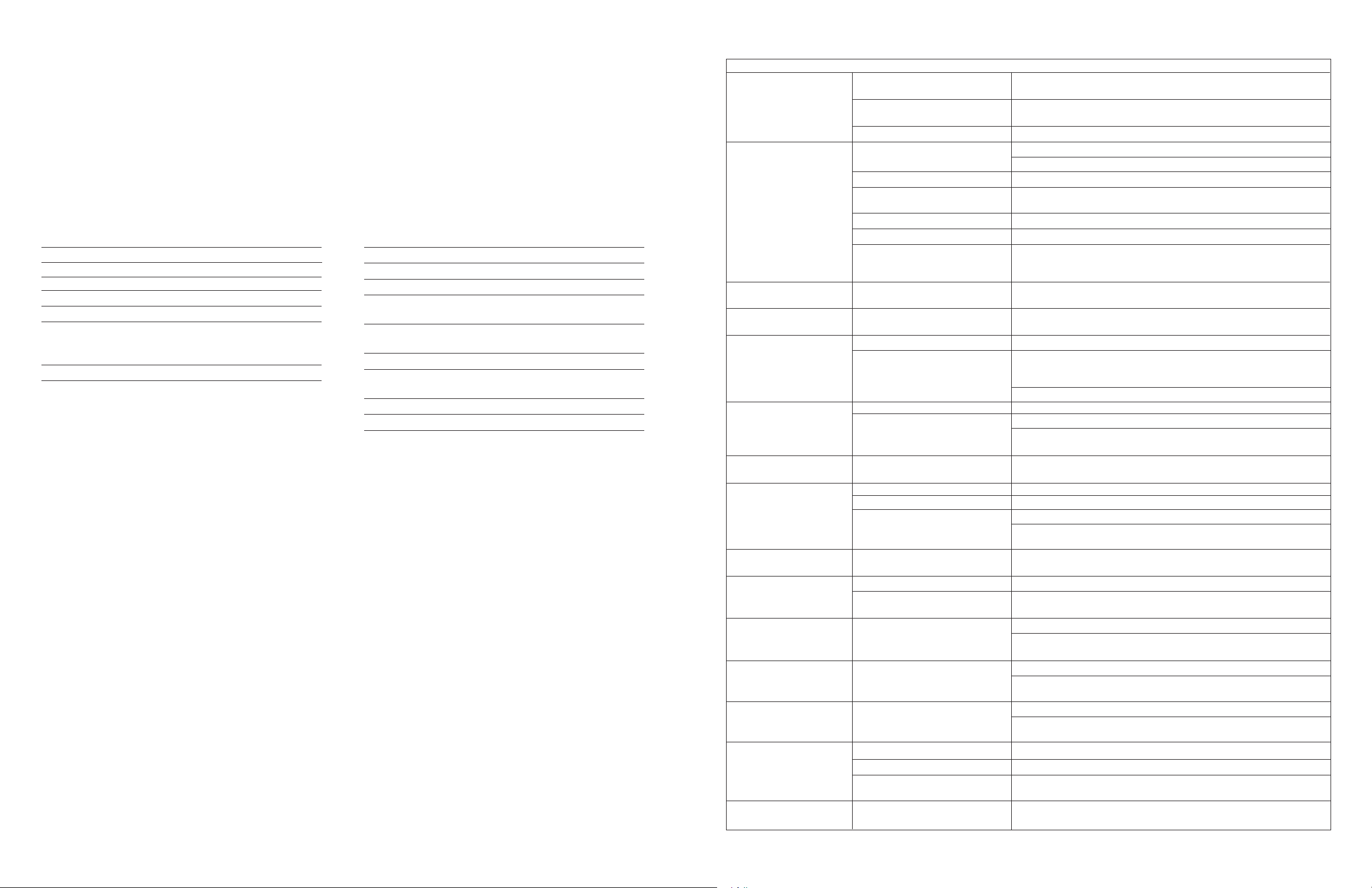
ADA890 Troubleshooting
Symptoms Possible Problem Solution
All indicators are off AC cord is not connected to wall outlet Check to see if the LED is illuminated on the rear of the subwoofer. If not,
connect AC power or try a different outlet.
Control speaker is not connected Connect control speaker to subwoofer
to the subwoofer
Power is off Press power button or use remote to turn on system
No Sound from any Speakers Power is not on Verify the AC line cord is plugged into the wall outlet
Verify power switch has been pressed (Display is on)
Volume setting is too low Raise master volume control
S/PDIF cable is not connected to Connect S/PDIF cable to DVD card and make sure all software drivers for computer are
DVD playback card set to proper output.
Signal cable is disconnected from sound card Connect analog signal cable from sound card (not DVD card) to ADA890 analog input
Right (Control) speaker is disconnected Connect right (Control) speaker
Computer not sending out signal Press the Diagnostic button on the rear of the ADA890 subwoofer. The speakers should
sequentially play a tone. If so, the ADA890 is working properly and problem is cables
or computer settings
Mute turns off unexpectedly Mute was re-pressed or a function System will un-mute whenever the mute button pressed again, if a function button is
was selected pressed, or if the volume control is rotated
Subwoofer emits very loud Signal cable is not completely inserted Make sure signal cable is inserted snugly into signal jack. Especially check the signal cable
humming/buzzing noise into signal jack on subwoofer at the computer end to make sure is completely plugged in
No sound from Subwoofer Subwoofer volume is too low Select Bass function and raise volume level
Press the Diagnostic button on the rear of the ADA890. This will sequentially play a tone
Sound source has very little low from each speaker, including the subwoofer. It will also set the system to the factory
frequency content default levels.
.WAV files often have little low frequency content. Try a music signal with more bass.
No sound from surround speakers Unit is not in a surround mode Press the mode button to select a surround mode.
Select surround level function and raise volume.
Surround level is too low Press and hold Treble and Bass buttons for 3 seconds to reset Treble, Bass, Center, and
Surround levels to default position.
Center and Surround buttons Unit is not in a surround mode Press the mode button to select a surround mode.
do not work
No sound from surround Surround bases are not connected Connect surround bases to rear of subwoofer.
speakers when detached Unit is not in a surround mode Press the mode button to select a surround mode.
Surround level is too low Select surround level function and raise volume
Press and hold Treble and Bass buttons for 3 seconds to reset Treble, Bass, Center, and
Surround levels to default position.
No playback from digital input Digital signal cable is not connected Connect digital signal cable to S/PDIF output of DVD playback card
to soundcard.
Sound is distorted Volume level too high Decrease master volume level
Sound source is distorted .WAV files are often of poor quality so distortion and noise are easily noticed with high
powered speakers. Try a different sound source like a music CD.
Not enough treble Treble setting is too low Select Treble function and increase level
Press and hold Treble and Bass buttons for 3 seconds to reset Treble, Bass, Center, and
Surround levels to default position
Too much treble Treble setting is too high Select Treble function and decrease level
Press and hold Treble and Bass buttons for 3 seconds to reset Treble, Bass, Center, and
Surround levels to default position
Too much bass or Bass setting is too high Select Bass function and decrease level
subwoofer distorted Press and hold Treble and Bass buttons for 3 seconds to reset Treble, Bass, Center, and
Surround levels to default position
Remote Control does not work Batteries are dead or not installed Replace or install new batteries
Remote is not pointed at speakers Point remote control at the right (control) speaker.
Remote signal path is blocked Removed any object that is blocking the signal from the remote to the right (control)
speaker next to the LCD display
No sound when playing DVD PCM Jack on dongle is connected Switch out the PCM RCA jack on dongle and connect the AC3 jack
to the system
6 7
Page 5

Introduction
Le système ADA890 est un système de haut-parleurs amplificateurs homologué THX®, bénéficiant pour le son d’ambiance et la reproduction stéréophonique des
technologies Dolby Digital et Pro Logic. L’effet stéréophonique peut être obtenu en des configurations de deux ou quatre haut-parleurs (Stereo X 2). Ces deux modes
exploitent le caisson d’extrêmes graves. Les entrées des amplificateurs peuvent traiter simultanément des signaux audionumériques (S/PDIF)* et analogiques. Le
système peut être utilisé avec des modules de jeux vidéo.
L’appareil est constitué d’un subwoofer (caisson d’extrêmes graves) et de deux haut-parleurs satellites. Cette combinaison assure une acoustique ambiophonique sur un
ordinateur de bureau en utilisant des haut-parleurs latéraux. Pour une ambiophonie améliorée, le haut-parleur supérieur de chaque satellite peut-être détaché, puis placé
sur son socle et relié par des fils de connexion longs. Cela permet de disposer les haut-parleurs de façon à obtenir des performances ambiophoniques optimales. Le circuit
d’équilibrage se réinitialise automatiquement pour prendre en compte les changements intervenus lors de la séparation des haut-parleurs.
Les haut-parleurs satellites sont protégés par un blindage antimagnétique ; ils peuvent donc être placés à proximité d’un moniteur sans entraîner de distorsion d’images.
Le haut-parleur du subwoofer n’est pas doté d’une protection antimagnétique ; il ne doit pas être placé à proximité d’un moniteur.
Les fréquences du subwoofer ne sont pas directionnelles : il n’est donc pas utile de le positionner en adoptant une relation particulière par rapport aux enceintes satellites.
L’installation du subwoofer sur le sol près d’un mur, dans un coin de pièce ou sous un bureau permet d’obtenir d’excellents résultats acoustiques.
Le haut-parleur satellite principal est pourvu d’un affichage à cristaux liquides signalant les diverses phases du fonctionnement. Un bouton principal du volume permet
d’ajuster séparément les sons graves, l’acoustique centrale et ambiophonique et les sons aigus. Une fois la fonction acoustique particulière réglée, le bouton sert à
nouveau au réglage principal du volume. Cette fonction est décrite avec d’autres fonctions dans la section consacrée à l’utilisation du système de haut-parleurs.
Une prise pour casque est disponible pour l’écoute individuelle. Une télécommande est fournie ; elle permet d’accéder à toutes les fonctions manuelles. Elle est munie
d’une fonction d’arrêt du son (silence) qui n’est pas disponible quand on utilise les commandes manuellement.
Un indicateur de mise sous tension par diode électroluminescente (DEL) et un interrupteur DIAGNOSTIC AUDIO SIGNAL (signal audio de diagnostic) sont prévus
pour aider au dépannage du système dans l’éventualité d’une anomalie de fonctionnement.
* Format d’interconnexion numérique DIF (Digital Interconnect Format) mis au point par Sony/Philips.
Qu’est-ce que le label THX ?
Les produits homologués THX doivent satisfaire à un ensemble de normes de performance définis par THX Lucasfilm®, une division de la fameuse maison de
production cinématographique Lucasfilm, Ltd. À l’origine, ces normes de performance THX furent créées pour répondre au souhait émis par George Lucas que les
bandes sonores originales des films Star Wars™, telle qu’elles seraient entendues dans les cinémas, reproduisent exactement les sons créés en studio d’enregistrement.
Plus tard, ces normes furent élargies pour s’appliquer au cinéma à domicile ; elles ont récemment été adaptées aux besoins spécifiques de reproduction sonore
ambiophonique sur plusieurs canaux de films ou jeux sur vidéo ou DVD reproduit sur le système multimédia d’un ordinateur individuel. Tous les produits multimédia
souhaitant recevoir l’homologation THX doivent satisfaire à ces exigences et normes de qualité rigoureuses avant de pouvoir arborer le label THX. Celui-ci vous garantit
que le produit multimédia homologué THX vous assurera de hautes performances et une fiabilité inégalables, pendant de nombreuses années à venir.
Installation
Ne pas brancher le connecteur secteur dans la prise murale tant que toutes les connexions ne sont pas établies.
L’installation de l’ADA890 peut se faire sous deux types de configuration. On utilise une installation à cinq éléments pour obtenir l’ambiophonie améliorée. On utilise
une installation à trois éléments pour le son stéréo/ambiophonie. Les deux modes d’utilisation sont décrits ci-dessous. Les haut-parleurs sont conditionnés et expédiés
en vue d’une configuration à 5 éléments. Suivre les instructions et le schéma de la figure 1 pour effectuer les connexions de ces cinq éléments.
L’ADA890 peut être utilisé avec les jeux tels que les Sony PlayStation et Sega Dreamcast avec entrée analogique, comme indiqué à la figure 2. La reproduction sonore,
avec cette méthode, produit un son ambiophonique Dolby® Pro Logic simulé lorsque le mode Pro Logic est choisi, permettant d’accentuer fortement les jeux. ADA890
peut également être utilisé avec tout système comportant des doubles sorties droite et gauche de type RCA.
Pour l’obtention du son Dolby® Digital avec l’ADA890 et la Sony PlayStation2, un convertisseur optique S/PDIF, sous le nom de OC1, est disponible en option. Il est
vendu sur le site Web de la société Altec à l’adresse www.altecmm.com.
Fonctionnement de l’ambiophonie améliorée (voir figure 1)
1) Connecter les haut-parleurs satellites gauche et droit.
Noter que les connecteurs DIN des haut-parleurs satellite gauche et droit sont codés par couleur et se branchent dans les indicateurs de la couleur apparentée à l’arrière
du subwoofer. À noter également que les connecteurs portent des flèches. Elles doivent être orientées vers le haut, conformément à la figure 1.
2) Connecter les haut-parleurs ambiophoniques gauches et droits.
Les connecteurs des haut-parleurs ambiophoniques gauche (BLANC) et droit (VIOLET) se branchent dans les entrées de code-couleur correspondant derrière
le subwoofer.
3) Connecter le subwoofer à l’ordinateur (voir Remarque 1)
Le fil codé en jaune vert relie l’entrée FRONT INPUT du subwoofer à la sortie correspondante sur l’ordinateur.
La prise noire permet de connecter l’entrée SURROUND (SURRD) INPUT du subwoofer à la sortie correspondante sur l’ordinateur.
La prise noire de type RCA permet de connecter l’entrée S/PDIF INPUT sur le subwoofer à un lecteur de DVD ou à la sortie correspondante sur l’ordinateur.
(Voir remarque 2)
Brancher le cordon d’alimentation dans une prise murale. Le système ADA890 est maintenant prêt à fonctionner.
Remarque 1 : il existe plusieurs fabricants de cartes sonores, et il est difficile de prévoir celle qui équipe votre ordinateur. La documentation de votre système vous
apportera des informations sur le type de sortie de signal que votre modèle utilise.
Remarque 2 : Le câble connecteur S/PDIF fourni se termine par des prises de type RCA. Dans certains cas, il se peut que ces dernières ne correspondent pas à la carte
son utilisée. Un câble de connection (Dongle) est fourni, pour adapter la sortie de l'ordinateur au câble S/PDIF. Il est possible que certaines cartes son ne soient pas
équipées d'une sortie analogique ou S/PDIF. Vous reporter au manuel d'utilisation de votre ordinateur pour plus d'informations sur la carte son utilisée sur votre modèle.
Voir la notice séparée et suivre les directives qui y sont données pour effectuer la connexion de la carte son à l'ADA890, avec liaison numérique directe, et obtenir une
performance THX optimale de l'ADA890.
Fonctionnement avec un module de jeux (voir figure 2)
Pour connecter un jeu vidéo à ADA890 :
1. Connecter les fiches RCA rouge et blanche du module de jeux vidéo aux jacks rouge et blanc correspondants du câble d’adaptation.
2. Connecter la fiche à l’une des extrémités du fil d’entrée codé en jaune vert. Connecter l’autre extrémité du fil codé en jaune vert à l’entrée FRONT INPUT
du subwoofer.
Fonctionnement du son ambiophonique/stéréo en champ proche (voir figure 3 et 4)
Pour installer la configuration à 3 haut-parleurs, suivre les directives et consulter la vue générale ci-dessous.
1) Séparer les haut-parleurs ambiophoniques gauche et droit de leurs socles en soulevant doucement chaque enceinte vers le haut (voir figure 3).
2) Retirer les fils gauche (BLANC) et droit (VIOLET) du subwoofer. (Ranger les socles de haut-parleur pour utilisation ultérieure)
3) Retirer les bouchons de caoutchouc au sommet des haut- parleurs satellite.
4) Monter les haut-parleurs ambiophoniques au-dessus des haut-parleurs satellites conformément à la figure 3. (La connexion aux haut-parleurs satellites est
automatiquement établie dès que les haut-parleurs ambiophoniques sont montés)
Le système ADA890 est maintenant prêt à fonctionner.
Positionnement des haut-parleurs (voir figure 5 et 6)
Toute l’information stéréo est diffusée par les haut-parleurs satellites et ambiophoniques. Le subwoofer ne contient pas d’informations stéréophoniques, et son acoustique
est non-directionnelle. Par conséquent, le subwoofer n’a pas besoin d’être positionné en tenant compte d’une relation particulière par rapport aux satellites. Placer le
subwoofer sur le sol à proximité d’un mur ou dans le coin d’une pièce pour obtenir des performances optimales sur les graves. Le subwoofer n’a pas de blindage
antimagnétique ; il ne doit pas être placé à proximité des écrans vidéo.*
* REMARQUE : éviter de poser des disquettes ou autres supports magnétiques sur le subwoofer.
Champ proche (3 éléments)
Les haut-parleurs ambiophoniques et satellites possèdent un blindage antimagnétique ; ils peuvent donc être placés à proximité d’un moniteur sans entraîner de distorsion
d’images. On obtient les meilleurs résultats stéréo en plaçant les haut-parleurs le plus loin possible les uns des autres.
Ambiophonie améliorée (5 éléments)
On obtient les meilleurs résultats de son d’ambiance en plaçant les haut-parleurs ambiophoniques légèrement en arrière de l’auditeur, et en maintenant entre eux à peu
près le mêm écart de séparation que pour les haut-parleurs satellites. On obtient d’excellents résultats lorsque les haut-parleurs ambiophoniques placés au même niveau
que les oreilles de l’auditeur, et légèrement au-dessus de celles-ci.
Fonctionnement du système de haut-parleurs (voir figure 7)
POWER (PUISSANCE). Appuyer sur ce bouton pour mettre le système sous tension. L’affichage à cristaux liquides s’allume et indique le dernier mode de
fonctionnement à avoir été utilisé. Un nouvel appui sur bouton met le système hors tension.
MODE SWITCH (changement de mode). La pression répétée de ce bouton permet d’accéder aux divers modes de fonctionnement. Lors de chaque pression sur le
bouton, l’affichage à cristaux liquides indique quel mode a été sélectionné. Les divers modes de fonctionnent sont décrits ci-dessous.
STEREO. Dans ce mode de fonctionnement, les informations sont obtenues de la partie frontale (FRONT INPUT) et les entrées S/PDIF* sont utilisées. Ces informations
peuvent être au format PCM*** ou Dolby Digital. Le circuit de décodage automatique traite l’un et l’autre. Si ce sont des informations PCM qui sont détectées, les
données seront décodées en stéréophonie. Si ce sont des informations Dolby Digital, tous les canaux seront mixés pour obtenir des informations stéréophoniques. Dans
ce dernier mode stéréo, le son ne provient que des haut-parleurs gauche et droit et du subwoofer. Le canal central et le haut-parleur d’ambiance ne fonctionnent pas dans
ce mode.
STEREO X 2. Le fonctionnement dans ce mode est identique à celui du mode STEREO ; la seule différence est que les deux enceintes d’ambiance (surround) sont
activées. Les haut-parleurs avant et d’ambiance gauches forment l’un des canaux stéréo, et les haut-parleurs avant et d’ambiance droits forment l’autre canal. Le niveau
des haut-parleurs d’ambiance peut être ajusté de manière séparée. Voir à la rubrique SURROUND (Mode d’ambiance) comment effectuer ce réglage. Les avantages du
fonctionnement sous ce mode sont un perfectionnement du mode stéréo et le rehaussement du niveau audio au sens large, par l’ajout de deux enceintes amplifiées. Le
canal central ne fonctionne pas dans ce mode.
PRO LOGIC. Dans ce mode, seules les informations obtenues de la sortie frontale (FRONT INPUT) sont utilisées. Les cinq haut-parleurs sont actifs, Les enceintes
avant, gauche et droite, apportent les informations stéréo ainsi que les informations centrales, les autres haut-parleurs surround apportent les informations d’ambiance.
Aucune entrée numérique (S/PDIF) n’est traitée dans ce mode.
** S/PDIF – Sony/Philips Digital Interconnect Format, format d’interconnexion numérique conçu en collaboration par Sony et Philips.
*** - Pulse Code Modulation, modulation par impulsions et codage.
QUAD. Dans ce mode, des entrées séparées sont utilisées pour les ensembles de canaux FRONT et SURROUND (voir figure 2). L’entrée de canal avant est l’entrée
codée en JAUNE VERT. L’entrée du canal d’ambiance est codée en NOIR. Les informations de l’avant (FRONT) sont décodées en stéréo et alimentent les haut-parleurs
avant gauche et droit, ainsi que le subwoofer. Les informations d’ambiance alimentent le canal d’ambiance et sont également envoyées au subwoofer. En mode QUAD,
les cinq haut-parleurs fonctionnent.
DOLBY DIGITAL. Dans ce mode, seules les informations obtenues des entrées FRONT et S/PDIF sont utilisées. Les informations du canal avant (FRONT) sont
décodées vers le canal stéréo et le subwoofer. Les informations S/PDIF peuvent être soit en format Dolby Digital, soit en format PCM ; le circuit de décodage
automatique traite l’un comme l’autre. S’il détecte des données PCM, celles-ci sont décodées en Pro logic. S’il détecte des données Dolby Digital, elles sont décodées
en Dolby Digital et les informations de partie frontale seront réduites à un niveau inférieur. Les cinq haut-parleurs fonctionnent en ce mode. Ce mode reproduit
simultanément des informations analogiques et numériques.
8 9
Page 6

Remarque : si votre ordinateur possède une carte sonore séparée, munie d’une sortie S/PDIF, vous pouvez utiliser cette sortie pour alimenter l’entrée S/PDIF avec les
informations du canal avant. Reportez-vous à la documentation fournie avec votre ordinateur à la section des signaux de sortie.
BASS (graves). Ce bouton assure deux modes de fonctionnement : le réglage du niveau des graves (BASS) et de l’acoustique centrale (CENTER).
A) RÉGLAGE DU NIVEAU DES GRAVES. Le réglage du niveau des graves est accessible dans tous les modes de fonctionnement. Appuyer sur ce bouton pour
augmenter/diminuer la réponse des graves. L’affichage à cristaux liquides indique BASS. Les indicateurs du volume indiquent également le dernier réglage effectué pour
cette commande. Tourner le bouton principal du volume dans le sens horaire pour accentuer les graves, et dans le sens anti-horaire pour les diminuer. Au fur et à mesure
de l’augmentation ou de la diminution du réglage du niveau des graves, les barres d’histogramme indiquant le niveau de volume indiqueront le changement du niveau
des graves en ordre ascendant ou descendant.
B) MODE DU NIVEAU CENTRAL. Cette fonction n’est opérationnelle que dans les modes Pro Logic et Dolby Digital. Maintenir le bouton BASS enfoncé jusqu’à
ce que l’indicateur de fonction affiche CENTER. Tourner le bouton principal du volume dans le sens horaire pour augmenter le volume central, et dans le sens antihoraire pour le baisser. Les barres d’histogramme indiquant le niveau de volume indiqueront le changement du niveau central en ordre ascendant ou descendant.
TREBLE (aigus). Ce bouton assure deux modes de fonctionnement : le réglage de niveau des aigus et de l’acoustique ambiophonique (SURROUND).
C) RÉGLAGE DU NIVEAU DES AIGUS. Le réglage du niveau des aigus est accessible dans tous les mode de fonctionnement. Appuyer sur ce bouton pour
augmenter/diminuer la réponse des aigus. L’affichage à cristaux liquides indique TREBLE. Les indicateurs du volume s’allument aussi en indiquant le dernier niveau
réglé. Tourner le bouton principal du volume dans le sens horaire pour accentuer les aigus et dans le sens anti-horaire pour les diminuer. Les barres d’histogramme
indiquant le niveau de volume indiqueront le changement du niveau des aigus en ordre ascendant ou descendant.
D) RÉGLAGE DU NIVEAU D’AMBIANCE. Cette fonction n’est opérationnelle que dans les modes Pro Logic, Dolby Digital, Quad et Stereo X 2. Maintenir le
bouton TREBLE enfoncé jusqu’à ce que l’affichage à cristaux liquides indique SURROUND. Tourner le bouton principal du volume dans le sens horaire pour augmenter
le volume ambiophonique, et dans le sens anti-horaire pour le baisser. Les barres d’histogramme indiquant le niveau de volume indiqueront le changement du niveau
ambiophonique en ordre ascendant ou descendant.
Test NOISE (test du bruit). Le test de bruit permet de vérifier l’état général de la chaîne audiophonique. Pour passer en mode NOISE, le système doit se trouver ne
mode DOLBY DIGITAL ou PRO LOGIC. Maintenir le bouton MODE enfoncé jusqu’à ce que l’affichage à cristaux liquides indique NOISE. (Lorsque le bouton du
mode est maintenu enfoncé en mode DOLBY DIGITAL, le LCD affiche temporairement STEREO. Toutefois, le mode est toujours DOLBY DIGITAL. En mode PRO
LOGIC, lorsque le bouton du mode est maintenu enfoncé, le LCD affiche temporairement QUAD ; toutefois, le mode est toujours PRO LOGIC).
Le test de bruit passe automatiquement de canal en canal, par pas de 2 secondes environ. Si le système fonctionne normalement, le bruit se fera entendre dans chaque
haut-parleur. Le bruit continuera à passer de canal en canal jusqu’à ce qu’il soit interrompu par appui du bouton MODE. L’objectif du test est d’assurer que chacun des
haut-parleurs est en fonctionnement.
Le bruit produit au cours du test est composé d’une vaste plage de fréquences audibles choisies pour permettre de tester chacun des haut-parleurs du système.
RÉGLAGE PRINCIPAL DU VOLUME. Le réglage principal du volume assure un grand nombre de fonctions. Il sert de commande générale du volume pour
l’ensemble du système et il permet également de régler séparément les niveaux des graves (BASS), de l’acoustique centrale (CENTER), des aigus (TREBLE) et des
sons d’ambiance (SURROUND). Si l’une de ces fonctions est sélectionnée sans être réglée dans les secondes qui suivent, la réglage principal du volume redevient
prioritaire.
RÉGLAGE DE LA FIDÉLITÉ UNIFORME. Pour régler les commandes des graves et des aigus BASS et TREBLE sur une fidélité uniforme (par défaut) et les
commandes d’acoustique centrale et ambiophonique SURROUND sur les niveaux de volume intermédiaires, appuyer en même temps sur les boutons BASS et TREBLE.
Il faut maintenir l’appui sur les boutons jusqu’à ce que l’affichage à cristaux liquides affiche les mots DOLBY DIGITAL. La réponse de l’amplificateur est maintenant
uniforme (linéaire). Des barres d’histogramme d’indication du niveau de volume s’affichent au milieu de l’affichage pour refléter la réponse uniforme de l’amplificateur.
Appuyer respectivement sur l’un ou l’autre des boutons BASS et TREBLE pour augmenter/diminuer la réponse des graves ou des aigus. Tourner le bouton du volume
dans le sens horaire pour augmenter le niveau, et dans le sens anti-horaire pour abaisser les niveaux par rapport au niveau de fidélité uniforme.
Pour accéder aux niveaux de volume de l’acoustique centrale (CENTER), l’appareil doit se trouver en mode Dolby Digital ou Pro Logic. Pour accéder aux niveaux de
volume (SURROUND), l’appareil peut se trouver ne mode Quad, Stereo X 2, Dolby Digital ou Pro Logic. Appuyer sur le bouton TREBLE jusqu’à ce que l’affichage
à cristaux liquides indique SURROUND, ou maintenez l’appui sur le contrôle des graves (BASS) jusqu’à ce que l’affichage à cristaux liquides affiche CENTER. Régler
le bouton du volume dans le sens horaire pour augmenter le volume, et dans le sens anti-horaire pour baisser le niveau de volume des canaux SURROUND ou CENTER.
UTILISATION DU CASQUE. (voir figure 8). La sortie casque est active dans tous les modes. Si une écoute privée est souhaitée, un prise jack pour casque est
disponible sur le côté de l’enceinte satellite de gauche. Le casque (non fourni) doit comporter une fiche de type jack de 3,5 mm de diamètre. Lorsque le casque est
branché à la prise de casque, les haut-parleurs n’émettent aucun son. La sortie de casque est amplifiée de manière indépendante et représente un mixage de tous les
canaux. Le bouton de contrôle du volume est utilisé pour ajuster le volume du casque. Il suffit de retirer la prise du casque pour rétablir l’amplification des enceintes.
INDICATEUR DE NIVEAU D’ALIMENTATION CA. (Veuillez noter que la diode électroluminescente [DEL] est placée sur la face avant du subwoofer). Sous une
tension d’alimentation normale, la DEL prend une couleur jaune verte. Cette DEL prend une couleur rouge si la tension d’alimentation dépasse le niveau de
fonctionnement normal. Si cela se produit, des circuits de protection électrique peuvent couper l’alimentation des amplificateurs audio. Leur fonctionnement est rétabli
lorsque la DEL revient à la couleur jaune verte. Si l’indicateur de niveau de tension prend une couleur rouge de manière continue, informer l’EDF ou les services
d‘électricité. Il se peut qu’ils aient à ramener la tension à des niveaux plus normaux.
TOUCHE DE DIAGNOSTIC. (Voir son emplacement à la figure 2.) S’il s’avère nécessaire de faire subir un test à l’ADA890, pour vérifier le bon fonctionnement des
haut-parleurs, appuyer sur cette touche. Tous les haut-parleurs reviennent à une réponse uniforme (linéaire), leur réglage par défaut, sans égard aux réglages précédents.
Une tonalité de test**** sera diffusée tour à tour par chacun des haut-parleurs. Noter si les haut-parleurs fonctionnent, ou si le son qu’ils émettent est anormal ou
déformé, ou si les niveaux sonores sont incorrects. Ces informations seront utiles au technicien du service d’assistance. À la fin du test, le mode revient à Dolby Digital,
quel qu’ait été le réglage du mode avant l’exécution du test.
Le test peut être exécuté autant de fois que nécessaire pour s’assurer du bon fonctionnement du système.
**** Pour tester le subwoofer, la fréquence de la tonalité s’adaptera en fonction des besoins du subwoofer
Fonctionnement de la commande à distance (voir figure 9)
La commande à distance peut effectuer la plupart des fonctions manuelles. Pour obtenir les meilleurs résultats, diriger la partie antérieure de la commande vers le
détecteur de signaux infrarouges indiqué à la figure 6. Les fonctions de la commande sont indiquées ci-après.
POWER (alimentation). Appuyer sur ce bouton pour mettre l’appareil sous tension. L’affichage à cristaux liquides s’allume et indique celui des modes qui a été
précédemment sélectionné. Appuyer une nouvelle fois pour mettre l’appareil hors tension.
TREBLE (aigus). Appuyer sur ce bouton si un réglage des aigus est souhaité. L’affichage à cristaux liquides affiche TREBLE. Pour augmenter ou diminuer le volume
des aigus, appuyer sur la partie du bouton VOL (volume) portant un signe plus (+) ou un signe moins (-). Les indicateurs de niveau affichés sur l’affichage à cristaux
liquides augmenteront en ordre ascendant lorsque le volume des aigus est augmenté et descendent puis disparaissent lorsque le volume des aigus est diminué.
BASS (graves). Appuyer sur ce bouton si un réglage des graves est souhaité. L’affichage à cristaux liquides affiche BASS. Pour augmenter ou diminuer le volume des
graves, appuyer sur la partie du bouton VOL(volume) portant un signe plus (+) ou un signe moins (-). Les indicateurs de niveau affichés sur l’affichage à cristaux liquides
augmenteront en ordre ascendant lorsque le volume des graves est augmenté et descendent puis disparaissent lorsque le volume des aigus est diminué.
MUTE (sourdine). Cette fonction n’est disponible que lorsque la commande à distance est utilisée. Appuyer sur ce bouton pour couper le son. Les indicateurs de volume,
sur l’affichage à cristaux liquides, disparaissent. L’indicateur de la fonction reste affiché. Appuyer sur le bouton une nouvelle fois pour rétablir le niveau sonore original.
Appuyer sur le bouton de n’importe quelle autre fonction pour rétablir le volume sonore.
CENTER (volume du canal central). Cette fonction n’est opérationnelle que dans les modes Pro Logic et Dolby Digital). Appuyer sur ce bouton pour ajuster le niveau
du volume du canal central. L ’af fichage à cristaux liquides af fiche CENTER. Ajuster le niveau du canal central en appuyant sur la partie du bouton VOL(volume) portant
un signe plus (+) ou un signe moins (-). L’affichage à cristaux liquides augmentera en ordre ascendant lorsque le volume est augmenté et ordre descendant lorsque le
volume est diminué.
SURR(SURROUND, ambiophonie). Cette fonction n’est opérationnelle que dans les modes Stereo X 2, Quad, Pro Logic et Dolby Digital. Appuyer sur ce bouton pour
ajuster le niveau du volume du canal d’ambiance. Ajuster le niveau du canal d’ambiance en appuyant sur la partie du bouton VOL (volume) portant un signe plus (+)
ou un signe moins (-). Les indicateurs de l’affichage à cristaux liquides augmenteront en ordre ascendant lorsque le volume est augmenté et en ordre descendant lorsque
le volume est diminué.
MODE. Appuyer sur ce bouton de manière répétée pour accéder aux divers modes de fonctionnement : STEREO, STEREO X 2, PRO LOGIC, DOLBY DIGITAL
et QUAD.
Caracteristiques
Puissance totale amplificateur 120 Watts
Sortie du système pour une
Sensibilité d'entrée analogique 300 mV pour amener l'amplificateur
Haut-Parleurs Amplificateurs Satellites
Réponse du système 27 Hz - 20 kHz
amplitude de crête 103 dB SPL @ 0,7 m
Impédance d'entrée > 10 kOhms
à la sortie maximale
Entrée digitale S/PDIF*
Amplificateurs Quatre unités 76,2 mm (3 pouces), pleine gamme
Deux haut-parleurs d’aigus de 31,8 mm (1 pouce)
Puissance 60 watts (15 watts par attaqueur)
Rapport signal/bruit >70 dB
Subwoofer
Attaqueur Une bobine mobile double de 203,2 mm
(8 pouces)
Puissance 60 watts
Fréquence de coupure 150 Hz
Rapport signal/bruit >70 dB
Alimentation Nécessaire
Europe/Royaume-Uni et divers pays d’Asie
230V/50Hz
États-Unis/Canada 120V/60Hz/360 W
Approuvée UL/CUL/EC
Dimensions
Subwoofer
365 mm de large x 260 mm de profondeur x 290 mm de haut
Haut-parleur principal
137 mm de large x 110 mm de profondeur x 162 mm de haut
Enceintes d’ambiance
110 mm de large x 104 mm de profondeur x 117 mm de haut
*Sony/Philips Digital Interconnect Format
10 11
Page 7

Dépannage – ADA890
SYMPTÔMES PROBLÈME POSSIBLE SOLUTION
Tous les indicateurs sont inactivés Le cordon secteur n’est pas branché dans la prise. Vérifier si la DEL à l’arrière du subwoofer est allumée. Si ce n’est pas le cas, enficher la prise su cordon
d’alimentation ou essayer une autre prise de courant.
L’enceinte principale n’est pas reliée au subwoofer. Relier l’enceinte principale au subwoofer.
Le système est éteint. Appuyer sur le bouton POWER ou utiliser la télécommande pour mettre le système sous tension.
Aucun son ne provient Le système n’est pas allumé. Vérifier que l’interrupteur marche/arrêt est activé (l’affichage est sous tension).
des haut-parleurs Le volume est trop bas. Augmenter le réglage principal du volume.
Le câble S/PDIF n’est pas connecté à la Connecter le câble S/PDIF à la carte DVD et s’assurer que tous les pilotes pour l’ordinateur sont
carte de lecture DVD. paramétrés pour la sortie correcte.
Le câble du signal est débranché de la carte sonore. Connecter le câble du signal analogique provenant de la carte sonore (et non la carte DVD) à l’entrée
analogique de l’ADA890.
L’enceinte droite (principale) est débranchée. Connecter l’enceinte droite (principale).
L’ordinateur n’envoie pas de signal. Appuyer sur le bouton Diagnostic, placé à l’arrière du subwoofer ADA890. Les haut-parleurs devraient,
chacun à leur tour, émettre une tonalité. Si c’est le cas, l’ADA890 fonctionne normalement et le problème
réside au niveau des câbles ou des paramètres de l’ordinateur.
L’arrêt du son MUTE Le bouton MUTE a été réactivé ou une fonction Le système annule la sourdine (l’arrêt du son) quand le bouton MUTE est réactivé, lorsque l’on appuie
intervient inopinément vient d’être sélectionnée. sur un bouton de fonction, ou si l’on tourne le bouton du volume.
Le subwoofer émet un Le câble de signal n’est pas enfoncé à fond dans Vérifier que le câble est enfoncé à fond dans son jack. Vérifier particulièrement du côté de l’ordinateur
bourdonnement très bruyant son jack sur le subwoofer. pour vérifier que la fiche est bien enfoncée à fond.
Aucun son ne provient du subwoofer Le volume du subwoofer est trop faible. Sélectionner la fonction des graves BASS et augmenter le volume.
Le son provenant de la source audio a un contenu Appuyer sur le bouton Diagnostic, placé à l'arrière du subwoofer ADA890. Les haut-parleurs devraient,
à faible teneur en basses fréquences. chacun à leur tour, émettre une tonalité. Le fait d'appuyer sur ce bouton remet également le système à ses
réglages d'usine.
Les fichiers .WAV ont souvent une faible teneur en basses fréquences. Essayer un signal musical
contenant plus de graves.
Aucun son ne provient du L'appareil n'est pas en mode SURROUND Appuyer sur le bouton MODE pour sélectionner un mode SURROUND.
subwoofer des enceintes d'ambiance (mode ambiophonique).
Le volume sonore du haut-parleur d'ambiance Sélectionner la fonction SURROUND et augmenter le volume.
est trop faible Appuyer sur TREBLE et BASS et maintenir 3 secondes pour remettre les aigus, les graves, l'acoustique
centrale et ambiophonique à leurs niveaux par défaut.
Les boutons CENTER et L'appareil n'est pas en mode SURROUND Appuyer sur le bouton MODE pour sélectionner un mode SURROUND.
SURROUND ne fonctionnent pas (ambiophonie).
Aucun son ne provient des Les bases ambiophoniques ne sont pas connectées Connecter les bases ambiophoniques à l'arrière du subwoofer.
enceintes d'ambiance lorsqu'elles L'appareil n'est pas en mode SURROUND Appuyer sur le bouton MODE pour sélectionner un mode SURROUND.
sont détachées (ambiophonie).
Le volume sonore du haut-parleur d'ambiance Sélectionner la fonction de niveau SURROUND et augmenter le volume
est trop faible Appuyer et maintenir la pression sur les boutons TREBLE et BASS pendant 3 secondes pour remettre les
aigus, les graves, l'acoustique centrale et ambiophonique à leurs niveaux par défaut.
Pas de lecture en provenance Le câble du signal numérique n'est pas connecté Connecter le câble du signal numérique à la sortie S/PDIF ou à la carte de lecture DVD.
de l'entrée numérique à la carte sonore.
Distorsion du son Le volume est trop élevé. Baisser le niveau acoustique principal.
Distorsion du son provenant de la source. Les fichiers .WAV sont souvent d'une qualité médiocre, et par ce fait les distorsions ou les bruits sont
plus aisément remarqués sur des enceintes amplifiées. Essayer une source différente, par exemple un
disque compact.
Sons aigus insuffisants Le réglage TREBLE est trop bas Sélectionner la fonction TREBLE et augmenter le niveau.
Appuyer sur TREBLE et BASS et maintenir 3 secondes pour remettre les aigus, les graves, l'acoustique
centrale et ambiophonique à leurs niveaux par défaut.
Sons aigus excessifs Le réglage TREBLE est trop élevé Sélectionner la fonction TREBLE et baisser le niveau.
Appuyer sur TREBLE et BASS et maintenir 3 secondes pour remettre les aigus, les graves, l'acoustique
centrale et ambiophonique à leurs niveaux par défaut.
Sons graves excessifs, ou distorsion Le réglage BASS est trop élevé Sélectionner la fonction BASS et baisser le niveau.
du son provenant du subwoofer Appuyer sur TREBLE et BASS et maintenir 3 secondes pour remettre les aigus, les graves, l'acoustique
centrale et ambiophonique à leurs niveaux par défaut.
La télécommande ne fonctionne pas Les piles sont mortes ou non installées Remplacer ou installer les piles
La télécommande n'est pas pointée vers Diriger la télécommande vers l'enceinte de droite (principale).
les haut-parleurs
Le chemin du signal distant est entravé Retirer le ou les objets empêchant le signal de parvenir de la commande à distance à l'enceinte de droite
(principale), à côté de l'affichage à cristaux liquides.
Aucun son n'est produit lors de la Le jack PCM du connecteur intermédiaire est Détacher le jack PCM du connecteur intermédiaire et brancher le jack AC3 au système.
lecture de DVD connecté au système.
12 13
Introducción
El ADA890 es un sistema de altavoces amplificado para multimedia de tecnología avanzada, certificado por THX®, que ofrece reproducción de sonido circundante y
estéreo Dolby Digital y Dolby Pro-Logic. El sonido estéreo puede funcionar en una configuración de 2 altavoces o de 4 altavoces (Stereo X2). Ambos modos utilizan
también el subaltavoz. Las entradas al amplificador pueden funcionar con señales de audio analógicas y digitales (S/PDIF)*. El sistema puede utilizarse también con los
sistemas de juegos para el hogar.
La unidad consta de un subaltavoz de graves y dos altavoces satélites. Esta combinación ofrece sonido circundante en un escritorio utilizando altavoces de disparo lateral.
Para obtener un mejor sonido circundante, la parte del altavoz superior de cada satélite puede separarse y colocarse en una plataforma suministrada, utilizando cables
largos de altavoz. Esto permite colocar los altavoces separados de forma de optimizar el rendimiento del sonido circundante. Los circuitos ecualizadores se reajustan
automáticamente para adaptarse a los cambios que ocurren cuando se separan los altavoces.
Los altavoces satélites tienen blindaje antimagnético y pueden colocarse cerca de un monitor sin perturbar las imágenes. El subaltavoz no tiene blindaje antimagnético
y no se debe colocar cerca de un monitor.
Las frecuencias del subaltavoz de graves no son direccionales, por lo cual no es necesario colocar dicho altavoz en ninguna posición en particular con respecto a
los altavoces satélites. Se consiguen excelentes resultados colocando el subaltavoz de graves en el piso, cerca de una pared o esquina de una habitación, o debajo de
un escritorio.
El altavoz satélite principal tiene una pantalla LCD que muestra las diversas condiciones de funcionamiento. Se utiliza un control maestro de volumen para ajustar por
separado los niveles de graves, central, circundante, y agudos. Una vez fijada cada una de las funciones, el control vuelve a transformarse en un control maestro de
volumen. Esta y otras funciones se explican en la sección “Uso del sistema de altavoces”.
El sistema tiene un conector para audífonos, que permiten oír en forma privada. Se suministra una unidad de control remoto que da acceso a todas las funciones manuales.
El control remoto tiene una función de silenciamiento que no está disponible cuando se usan los controles de forma manual.
El sistema tiene un INDICADOR LED DE ENCENDIDO y un interruptor de DIAGNÓSTICO DE LA SEÑAL DE AUDIO, que permiten investigar problemas en caso
de sospecharse una falla del sistema.
*Formato de Interconexión Digital de Sony/Phillips
Qué es la certificación de THX
Los productos certificados por THX deben cumplir con una serie exclusiva de normas de rendimiento establecidas por THX Lucasfilm®, una división de la renombrada
compañía de producción cinematográfica, Lucasfilm, Ltd. Estas normas de rendimiento de THX surgieron originalmente en respuesta al deseo personal de Geor ge Lucas
de que las bandas de sonido de Star Wars™ en los cines se correspondieran con las creadas en el estudio de sonido. Más tarde, esas normas se extendieron a los sistemas
de cine en casa ( “Home Theater”) y se adaptaron recientemente a las necesidades especializadas de la reproducción de sonido circundante multicanal de películas y
juegos, en DVD, reproducidos en sistemas multimedia de ordenadores personales (PC). Todos los productos multimedia que aspiran a la certificación THX tienen que
cumplir con estos rigurosos requisitos de rendimiento y calidad, a fin de poder lucir el logotipo THX, que es una garantía de que este producto multimedia certificado
por THX le proporcionará un rendimiento y una fiabilidad de la más alta calidad, durante muchos años.
Instalación
No inserte el enchufe de alimentación de CA en el tomacorriente de pared hasta haber hecho todas las conexiones.
El ADA890 puede instalarse en dos configuraciones. Para obtener sonido CIRCUNDANTE MEJORADO, se usa una configuración de 5 piezas. Para el sonido de campo
próximo ESTÉREO/CIRCUNDANTE, se usa una configuración de 3 piezas. Los dos modos de operación se describen más abajo. Los altavoces se empacan y se envían
en la configuración de 5 piezas. Para hacer las conexiones de las 5 piezas, siga las instrucciones y diagramas que aparecen en la Figura 1.
El ADA890 puede usarse con sistemas de juegos como el Sony PlayStation y con Sega Dreamcast con la entrada analógica mostrada en la Figura 2. La reproducción
con este método dará por resultado un sonido simulado circundante Dolby® ProLogic, en el modo ProLogic, generando una excelente experiencia en los juegos. El
ADA890 puede utilizarse también con cualquier otro sistema de sonido que tenga dobles salidas RCA derecha e izquierda.
Para el sonido Dolby® digital con el ADA890 y el Sony PlayStation2, hay un convertidor opcional de óptico a S/PDIF*, llamado OC1, que se vende en el sitio web de
Altec, www.altecmm.com.
Funcionamiento con sonido circundante mejorado (vea la Figura 1)
1) Conecte los altavoces satélites izquierdo y derecho.
Observe que los conectores DIN de los altavoces satélites izquierdo y derecho están codificados por color y se conectan a los conectores del mismo color en la parte
posterior del subaltavoz. Observe también que los conectores tienen flechas. Estas flechas deben estar hacia arriba, como se muestra en la Figura 1.
2) Conecte los altavoces circundantes izquierdo y derecho.
Los conectores izquierdo (BLANCO) y derecho (MORADO) de los altavoces circundantes se conectan en las correspondientes entradas coloreadas de la parte
posterior del subaltavoz.
3) Conecte el subaltavoz al ordenador (vea la Nota 1).
El alambre verde conecta la ENTRADA FRONTAL del subaltavoz a la correspondiente salida de audio del ordenador.
El alambre negro conecta la ENTRADA CIRCUNDANTE (SURRD) del subaltavoz a la correspondiente salida de audio del ordenador.
El conector negro tipo RCA se utiliza para conectar la ENTRADAS/PDIF del subaltavoz a un reproductor DVD o a la correspondiente salida de audio del ordenador
(Vea la nota 2).
Conecte el enchufe de alimentación eléctrica de CA al tomacorriente en la pared. Su sistema ADA890 se encuentra listo para usar.
Nota 1: Su ordenador puede tener diferentes tarjetas de sonido. La documentación del ordenador contendrá información sobre las salidas de la tarjeta de sonido que
se utilizan en su modelo.
Nota 2: El cable de conexión S/PDIF suministrado tiene conectores tipo RCA. En algunos casos, este tipo de conector puede no corresponderse con la tarjeta de
sonido. Se suministra un cable adaptador que compatibiliza la salida del ordenador y el cable S/PDIF. Algunas tarjetas de sonid o pueden no tener una salida analógica
Page 8

o S/PDIF posterior. Consulte la documentación de su ordenador para obtener información sobre la tarjeta de sonido utilizada en su modelo. Vea el inserto separado
para conectar la tarjeta de sonido al ADA890 para la entrada digital directa a fin de que el ADA890 funcione correctamente según la norma THX. Si cumple con lo
indicado en ese inserto, obtendrá un rendimiento óptimo.
Uso con sistemas de juegos (vea la Figura 2)
Para conectar un sistema de juegos al ADA890:
1. Conecte los conectores RCA rojo y blanco del sistema de juegos a los respectivos conectores rojo y blanco del cable adaptador.
2. Conecte el conector verde del cable adaptador a un extremo del cable de entrada verde. Conecte el otro extremo del cable de entrada verde a la ENTRADA FRONT AL
del subaltavoz.
Funcionamiento con sonido estéreo/circundante en el campo próximo (vea las Figuras 3 y 4)
Si desea convertir el sistema a uno de 3 altavoces, siga las instrucciones y los diagramas que aparecen más abajo.
1) Separe los altavoces circundantes izquierdo y derecho de sus bases, tirando suavemente del altavoz hacia arriba (vea la Figura 3).
2) Saque los alambres izquierdo (BLANCO) y derecho (MORADO) del subaltavoz.
(Guarde las bases de los altavoces para usarlas más adelante).
3) Saque los tapones de goma suministrados de la parte superior de los altavoces satélites.
4) Monte los altavoces circundantes encima de los altavoces satélites, como se muestra en la Figura 3.
(Las conexiones a los altavoces satélites se efectúan automáticamente una vez montados los altavoces circundantes).
Su sistema ADA890 se encuentra listo para usar.
Lugar de colocación de los altavoces (vea las Figuras 5 y 6)
Toda la información en estéreo se oye desde los altavoces satélites y circundantes. El subaltavoz no contiene información en estéreo y su sonido no es direccional. Por
lo tanto, no es necesario colocar dicho altavoz en ninguna posición en particular con respecto a los altavoces satélites. Se consiguen una máxima eficiencia de graves
colocando el subaltavoz de graves en el piso, cerca de una pared o esquina de una habitación. El subaltavoz no tiene blindaje antimagnético y no se debe colocar cerca
de monitores de video.*
Campo próximo (3 piezas)
Los altavoces satélites tienen blindaje antimagnético y pueden colocarse cerca de un monitor sin distorsionar las imágenes de video. Para obtener el mejor efecto de
estéreo, conviene colocar los altavoces lo más separados posible, dentro de lo que resulte práctico.
Sonido circundante mejorado (5 piezas)
Se obtienen los mejores efectos de sonido circundante colocando los altavoces circundantes traseros ligeramente detrás del usuario y separados aproximadamente la
misma distancia que los altavoces satélites. Se obtienen excelentes resultados cuando los altavoces circundantes están alineados con las orejas del escucha, y a una altura
ligeramente mayor.
* Nota: Se debe tener cuidado de no poner disquetes u otros medios magnéticos sobre el subaltavoz.
Uso del sistema de altavoces (vea la Figura 7)
POWER. Presione este botón para encender el sistema. Se iluminará la pantalla LCD y mostrará el último modo de operación. Presiónelo otra vez para apagarlo.
INTERRUPTOR MODE.Al presionar este interruptor reiteradamente, se accede a varios modos de operación. Cada vez que se presiona el interruptor, la pantalla LCD
indica qué modo se ha seleccionado. Acontinuación se describen los diferentes modos de operación.
ESTÉREO. En este modo, se utiliza la información obtenida de las entradas FRONTAL y S/PDIF**. La información frontal se decodifica para obtener estéreo. La
información S/PDIF puede ser PCM** o Dolby Digital. El circuito de decodificación automática procesará cualquiera de los dos. Si detecta PCM, decodificará a estéreo.
Si detecta Dolby Digital, se mezclarán todos los canales para generar información en estéreo. En este modo de estéreo, el sonido solamente saldrá de los altavoces
frontales izquierdo y derecho y del subaltavoz. El canal central y el altavoz circundante no funcionarán en este modo.
ESTÉREO X 2. En este modo, el funcionamiento es el mismo que en el modo ESTÉREO. La diferencia es que se activarán los dos altavoces circundantes. Los altavoces
circundantes frontal izquierdo y circundante izquierdo formarán un canal de estéreo, y los altavoces frontal derecho y circundante derecho formarán el otro canal. El
nivel de los altavoces circundantes puede ajustarse por separado. Vea la sección del modo de operación CIRCUNDANTE para hacer este ajuste. Las ventajas de
funcionar en este modo son que el efecto estéreo puede mejorarse y el audio total se aumenta por medio del uso de dos altavoces amplificados adicionales. El canal
central no funciona en este modo.
PRO LOGIC. En este modo, solamente se usa la información obtenida de la entrada analógica frontal. Se activan los cinco altavoces. Los altavoces frontales derecho
e izquierdo proveerán la información en estéreo y central, y los altavoces circundantes proveerán la información circundante. En este modo, no se procesarán entradas
digitales (S/PDIF).
**S/PDIF – Formato de interconexión digital de Sony/Philips
**PCM – Modulación de código de pulso
QUAD. En este modo, se usan entradas separadas para los canales FRONTAL y CIRCUNDANTE (vea la Figura 2). La entrada del canal frontal es la entrada VERDE.
La entrada del canal circundante es la entrada NEGRA. La información frontal se decodifica a estéreo y alimenta los altavoces frontales izquierdo y derecho y el
subaltavoz. La información circundante provee el canal circundante y también se envía al subaltavoz. En el modo QUAD, funcionan los cinco altavoces.
DOLBY DIGITAL. En este modo, solamente se utiliza la información obtenida de las entradas FRONTAL y S/PDIF. La información frontal se decodifica a estéreo y
al subaltavoz. La información S/PDIF puede ser Dolby Digital o PCM. El circuito de decodificación automática procesa cualquiera de las dos señales. Si detecta PCM,
decodificará a Pro Logic. Si detecta Dolby Digital, decodificará a Dolby Digital y la información frontal se reducirá a un nivel más bajo. En este modo, funcionan los
cinco altavoces. Este modo reproduce señales analógicas y digitales simultáneamente.
Nota: Si su ordenador tiene una tarjeta de sonido separada con una salida S/PDIF, puede usar dicha salida para alimentar la entrada S/PDIF con la información de canal
frontal. Para obtener información sobre las salidas, consulte la documentación del sistema.
14 15
BASS. El botón BASS permite operar en dos modos: control de nivel de GRAVES o control de nivel del CENTRO.
A) CONTROL DE NIVEL DE GRAVES. El control de nivel de graves es accesible en todos los modos de operación. Presione el botón BASS si desea aumentar o
disminuir la respuesta de GRAVES. La pantalla LCD indicará BASS. Además, los indicadores de nivel mostrarán la última opción elegida en el control. Haga girar el
control de volumen maestro en sentido horario para aumentar los graves y en sentido antihorario para disminuir los graves. Al aumentar o disminuir el volumen, las
barras indicadoras de nivel de volumen indicarán el cambio de graves, en orden creciente o decreciente.
B) MODO DE NIVEL DELCENTRO. Esta función sólo se activa en el modo Pro Logic y Dolby Digital. Mantenga presionado el botón BASS hasta que el indicador
de función indique CENTER. Haga girar el control de volumen maestro en sentido horario para aumentar el volumen del centro, y en sentido antihorario para hacerlo
disminuir. Las barras indicadoras de nivel de volumen mostrarán el cambio de volumen, en orden creciente o decreciente.
TREBLE. El botón TREBLE permite funcionar en dos modos: control de nivel de AGUDOS o control de nivel CIRCUNDANTE.
C) CONTROLDE NIVELDE AGUDOS. El control de nivel de agudos es accesible en todos los modos de operación. Presione el botón si desea aumentar o disminuir
la respuesta de AGUDOS. La pantalla LCD indicará TREBLE. Además, el indicador de nivel de volumen mostrará la última opción elegida en el control. Haga girar el
control de volumen maestro en sentido horario para aumentar los agudos y en sentido antihorario para disminuir los agudos. Al aumentar o disminuir el volumen, las
barras indicadoras mostrarán el cambio de agudos, en orden creciente o decreciente.
D) CONTROL DE NIVEL CIRCUNDANTE. Esta función sólo funciona en los modos Pro Logic, Dolby Digital, Quad y Stereo X2. Mantenga presionado el botón
TREBLE hasta que la pantalla LCD indique SURROUND. Haga girar el control de volumen maestro en sentido horario para aumentar el volumen circundante y en
sentido antihorario para hacerlo disminuir. Las barras indicadoras de volumen mostrarán el cambio de volumen en orden creciente o decreciente.
PRUEBA DE RUIDO. Para verificar el sonido general del sistema, se provee una prueba de ruido. Para ingresar al modo de RUIDO, el sistema debe estar en el modo
DOLBY DIGITAL o PRO LOGIC. Presione el botón MODE hasta que la pantalla LCD indique NOISE. (Mientras mantiene presionado el botón en el modo DOLBY
DIGITAL, el LCD mostrará temporalmente ESTÉREO, pero el modo seguirá siendo DOLBY DIGITAL. En el modo PRO LOGIC, mientras mantiene presionado el
botón MODE, la pantalla LCD mostrará temporalmente QUAD. No obstante, el modo seguirá siendo PRO LOGIC).
El ruido pasará por cada canal en etapas de aproximadamente 2 segundos. El ruido se oirá en cada altavoz si el sistema está funcionando correctamente. El ruido
continuará circulando por cada canal hasta que se interrumpa al presionar el botón MODE. El propósito de la prueba es verificar que cada uno de los altavoces esté
funcionando.
El ruido generado se compone de un amplio espectro de frecuencias de audio que sirven para probar todos los altavoces del sistema.
CONTROL DE VOLUMEN MAESTRO. El CONTROL DE VOLUMEN MAESTRO provee muchas funciones. Funciona como control de volumen maestro para el
sistema entero, y puede usarse también para ajustar por separado los niveles de volumen de GRAVES, CENTRO, AGUDOS, y CIRCUNDANTE. Si se selecciona
cualquiera de estas funciones y no se ajusta la misma en unos segundos, el control vuelve a ser un control de volumen maestro.
OPCIONES DE RESPUESTA PLANA. Para fijar los controles de GRAVES y AGUDOS a una respuesta plana (la respuesta predeterminada) y los controles de
CENTRO y CIRCUNDANTE a posiciones de nivel medio, se deben presionar los botones BASS y TREBLE al mismo tiempo. Se deben mantener presionados los
botones hasta que la pantalla LCD indique DOLBY DIGITAL. La respuesta del amplificador será ahora plana (lineal). Las barras indicadoras de nivel de volumen
aparecerán en el medio de la pantalla para indicar la respuesta plana del amplificador. Si desea aumentar o disminuir la respuesta de GRAVES o AGUDOS, presione el
botón BASS o TREBLE, respectivamente. Haga girar el control de volumen en sentido horario para aumentar los niveles y en sentido horario para disminuirlos con
respecto al nivel de respuesta plana.
Para obtener acceso a los niveles de volumen de CENTRO, la unidad debe puede estar en el modo Dolby Digital o en el modo Pro Logic. Para obtener acceso a los
niveles de volumen de CIRCUNDANTE, la unidad puede estar en el modo Quad, Stereo X2, Dolby Digital o Pro Logic. Presione el botón TREBLE hasta que la pantalla
LCD indique SURROUND, o sostenga el control BASS hasta que la pantalla indique CENTER. Ajuste el control de volumen MAESTRO en sentido horario para
aumentar el nivel de volumen de los canales CIRCUNDANTE o CENTRO.
USO DE AUDÍFONOS. (Vea la Figura 8). La salida de audífonos está activa en todos los modos. Si se desea oír en forma privada, hay una salida de audífono en el
costado del altavoz satélite izquierdo. Un audífono (no se suministra) con un conector estéreo de 3,5 mm (1/8”). Cuando se conecta el audífono al correspondiente
conector, los altavoces quedan silenciados. La salida de audífono tiene amplificación separada y tendrá todos los canales mezclados. El control maestro de volumen se
utiliza para ajustar el volumen de audífono. Para reactivar la amplificación de los altavoces, retire el conector de audífonos.
INDICADOR DE NIVEL DE CA. (Nota: el LED está ubicado en el frente del subaltavoz). En condiciones de voltaje normal de operación, el LED se iluminará en
verde. El LED se pondrá rojo cuando el voltaje de la línea exceda el voltaje de operación normal. En este caso, los circuitos protectores pueden apagar los amplificadores
de audio. Los amplificadores volverán a funcionar cuando el indicador de alimentación vuelva a verde. Si el indicador está rojo continuamente, informe a la compañía
de electricidad. Puede ser necesario que reduzcan el voltaje de la línea a los niveles normales.
INTERRUPTOR DE DIAGNÓSTICO. (Vea la ubicación del interruptor en la Figura 2). Si fuere necesario probar el ADA890 para verificar que todos los altavoces
estén funcionando correctamente, presione este interruptor. Todos los altavoces volverán a una respuesta plana (predeterminada), cualesquiera sean los parámetros
anteriores. Se oirá una secuencia de tonos de prueba**** por separado en cada altavoz. Vea si los altavoces están funcionando o si el sonido está distorsionado, o si los
niveles de los altavoces son incorrectos. Esta información ayudará al técnico de servicio. Al final de la prueba, el modo volverá a Dolby Digital, cualquiera sea el modo
previo a la realización de la prueba.
Esta prueba puede llevarse a cabo tantas veces como sea necesario para asegurar que el sistema esté funcionando correctamente.
****Para probar el subaltavoz, la frecuencia del tono cambiará a una frecuencia apropiada para dicha prueba.
Uso del control remoto (vea la Figura 9)
El control remoto puede realizar la mayoría de las funciones manuales. Para obtener el mejor funcionamiento, apunte la parte frontal del control hacia el detector
infrarrojo, según se muestra en la Figura 6. Acontinuación se enumeran las funciones del control.
POWER. Presione este botón para encender el sistema. Se iluminará la pantalla LCD y mostrará uno de los modos seleccionados anteriormente. Presiónelo otra vez
para apagarlo.
TREBLE. Presione este botón si desea ajustar el nivel de AGUDOS. La pantalla LCD indicará TREBLE. Para aumentar o disminuir el volumen de agudos, presione
las teclas de más (+) o de menos (-) del botón VOL. Los indicadores de nivel de volumen en la pantalla LCD aumentarán en orden ascendente al aumentar el volumen
Page 9

de agudos y se apagarán en orden decreciente al disminuir el volumen de agudos.
BASS. Presione este botón si desea ajustar el nivel de GRAVES. La pantalla LCD indicará BASS. Para aumentar o disminuir el volumen de graves, presione las teclas
de más (+) o de menos (-) del botón VOL. Los indicadores de nivel de volumen en la pantalla LCD aumentarán en orden ascendente al aumentar el volumen de graves
y se apagarán en orden decreciente al disminuir el volumen de graves.
MUTE. Esta función de silenciamiento sólo está disponible en el control remoto. Presione este botón para silenciar el sonido. Los indicadores de nivel en la pantalla
LCD se apagarán. El indicador de función permanecerá encendido. Presione otra vez este botón para reactivar el sonido.
Presione cualquier otra función y el sonido se reactivará.
CENTER. Esta función sólo funciona en los modos Pro Logic o Dolby Digital. Presione este botón para ajustar el nivel de volumen del canal central. La pantalla LCD
indicará CENTER. Fije el nivel central utilizando las teclas de más (+) o de menos (-) del botón VOL. Los indicadores de nivel de volumen de la pantalla LCD
aumentarán en orden creciente al aumentar el volumen, y se apagarán en orden decreciente al disminuir el volumen.
SURR.(CIRCUNDANTE). Esta función sólo funciona en los modos Stereo X2, Quad, Pro Logic y Dolby Digital. Presione este botón para ajustar el nivel de volumen
del canal circundante. Fije el nivel circundante utilizando las teclas de más (+) o de menos (-) del botón VOL. Los indicadores de nivel de volumen de la pantalla LCD
aumentarán en orden creciente al aumentar el volumen, y se apagarán en orden decreciente al disminuir el volumen.
MODE. Al presionar reiteradamente este botón, se accede a todos los modos de operación: STEREO, STEREO X2, PRO LOGIC, DOLBY DIGITALy QUAD.
Especificaciones
Respuesta del sistema 27 Hz a 20 kHz
Potencia total del amplificador 120 vatios
Salida máxima del sistema 103 dB SPL a 0,7 m
Impedancia de entrada > 10 kilo-ohmios
Sensibilidad de entrada analógica 300 mV para salida plena
Entrada digital S/PDIF*
Altavoces Satélites
Excitadores Cuatro de 76,2 mm (3 pulgadas) y pleno rango
Dos altavoces de agudos de 31,8 mm (1
pulgada)
Potencia 60 vatios (15 vatios por satélite)
Subaltavoz
Requisitos De Alimentación
Europa, Reino Unido, y diversos países asiáticos
Relación señal-ruido >70 dB
Excitador Uno de 203,2 mm
(8 pulgadas) con doble bobina de voz
Potencia 60 vatios
Frecuencia de cruce 150 Hz
Relación señal-ruido >70 dB
EE.UU. y CANADÁ 120 V/60 Hz/360 W
230 V/50 Hz
Aprobado por UL/cUL/CE
Dimensiones
Subaltavoz 365 mm ancho x 260 mm fondo x 235 mm altura
Altavoz principal 137 ancho x 110 mm fondo x 162 mm altura
Circundantes 110 ancho x 104 mm fondo x 117 mm altura
*Formato de Interconexión Digital de Sony/Phillips
ADA890 – Problemas y soluciones
Síntomas
Todos los indicadores están
apagados
No hay sonido en ningún altavoz
El silenciamiento se apaga
inesperadamente
El subaltavoz emite un zumbido
muy fuerte
No hay sonido en el subaltavoz
No hay sonido en los altavoces
circundantes
Los botones Center y Surround no funcionan
No hay sonido en los altavoces
circundantes al separarlos
No se reproduce la entrada digital
El sonido está distorsionado
No hay suficientes agudos
Demasiados agudos
Demasiados graves o el subaltavoz
distorsiona
El control remoto no funciona
No hay sonido al reproducir DVD
Posible problema
El cable de alimentación no está conectado al
tomacorriente
El altavoz de control no está conectado al subaltavoz
El sistema está apagado
El sistema no está encendido
El nivel de volumen es demasiado bajo
El cable S/PDIF no está conectado a la tarjeta
reproductora de DVD
El cable de señal está desconectado de la tarjeta de
sonido
El altavoz derecho (de control) está desconectado
El ordenador no está enviando una señal de salida
Se presionó otra vez el botón de silenciamiento o se
escogió una función
El cable de señal no está totalmente inserto en el
conector de señal del subaltavoz
El volumen del subaltavoz es demasiado bajo
La fuente de sonido tiene muy poco contenido de
bajas frecuencias
La unidad no está en el modo circundante
El nivel circundante es demasiado bajo
La unidad no está en el modo circundante
Las bases circundantes no están conectadas
La unidad no está en el modo circundante
El nivel circundante es demasiado bajo
El cable de señal digital no está conectado a la tarjeta de sonido
El nivel de volumen es demasiado alto
La fuente de sonido está distorsionada
El nivel de agudos es demasiado bajo
El nivel de agudos es demasiado alto
El nivel de graves es demasiado alto
Las baterías están descargadas o no están instaladas
El control remoto no está apuntando a los altavoces
El camino de la señal remota está obstruido
El cable PCM del adaptador está conectado al sistema
Solución
Vea si el LED está iluminado en la parte trasera del subaltavoz. Si no lo está, conecte la corriente o
pruebe con otro tomacorriente.
Conecte el altavoz de control al subaltavoz
Presione el botón de encendido o use el control remoto para encender el sistema
Verifique que el cable de alimentación esté enchufado al tomacorriente
Verifique que se haya presionado el interruptor de encendido (la pantalla debe estar iluminada)
Suba el control de volumen maestro
Conecte el cable S/PDIF a la tarjeta DVD y verifique que todos los controladores de software del
ordenador estén configurados con la salida correcta
Conecte el cable de señal analógica de la tarjeta de sonido (no de la tarjeta DVD) a la entrada analógica
del ADA890
Conecte el altavoz derecho (de control)
Presione el botón de Diagnóstico en la parte trasera del subaltavoz del ADA890. Los altavoces deberían
reproducir un tono secuencialmente. Si es así, el ADA890 está funcionando correctamente y el
problema se debe a los cables o a la configuración del ordenador
El sistema anula el silenciamiento cuando se presiona nuevamente el botón de silenciamiento, si se
presiona un botón de función, o si se hace girar el control de volumen
Verifique que el cable esté bien inserto en el conector de señal; revise particularmente el cable de señal
en el extremo del ordenador para comprobar que esté bien enchufado
Seleccione la función Graves y suba el nivel de volumen
Presione el botón de Diagnóstico en la parte trasera del ADA890. Con esto, se reproducirá un tono en
cada altavoz, incluido el subaltavoz. También reinicializará el sistema con los niveles predeterminados
en fábrica
Los archivos .WAV tienen a menudo un contenido muy escaso de bajas frecuencias. Pruebe con una
señal musical con más graves
Presione el botón de modo para seleccionar un modo circundante
Seleccione la función de nivel circundante y suba el volumen
Presione y sostenga los botones Treble y Bass durante 3 segundos para reajustar los niveles de Agudos,
Graves, Centro, y Circundante a la posición predeterminada
Presione el botón de modo para seleccionar un modo circundante.
Conecte las bases circundantes a la parte posterior del subaltavoz
Presione el botón de modo para seleccionar un modo circundante
Seleccione la función de nivel circundante y suba el volumen
Presione y sostenga los botones Treble y Bass durante 3 segundos para reajustar los niveles de Agudos,
Graves, Centro, y Circundante a la posición predeterminada
Conecte el cable de señal digital a la salida S/PDIF de la tarjeta reproductora de DVD
Disminuya el nivel de volumen maestro
Los archivos .WAV son a menudo de baja calidad, por lo cual la distorsión y el ruido se notan
fácilmente con los altavoces autoamplificados. Pruebe una fuente distinta de sonido, como un CD de
música
Seleccione la función de Agudos y aumente el nivel
Presione y sostenga los botones Treble y Bass durante 3 segundos para reajustar los niveles de Agudos,
Graves, Centro, y Circundante a la posición predeterminada
Seleccione la función de Agudos y disminuya el nivel
Presione y sostenga los botones Treble y Bass durante 3 segundos para reajustar los niveles de Agudos,
Graves, Centro, y Circundante a la posición predeterminada
Seleccione la función Graves y disminuya el nivel
Presione y sostenga los botones Treble y Bass durante 3 segundos para reajustar los niveles de Agudos,
Graves, Centro, y Circundante a la posición predeterminada
Coloque de nuevo las baterías, o instale nuevas baterías
Apunte el control remoto al altavoz derecho (de control)
Saque cualquier objeto que obstruya la señal del control remoto al altavoz derecho (de control) al lado
de la pantalla LCD
Desconecte el conector RCS PCM en el adaptador y conecte el conector AC3 al sistema
16 17
Page 10

Introduzione
Lo ADA890 è un sistema tecnicamente avanzato di altoparlanti multimediali amplificati, omologato da THX®, che produce suono Dolby Digitale e Pro Logic surround
con riproduzione stereofonica. Il suono stereofonico può prodursi in una configurazione a 2 altoparlanti o una configurazione a 4 altoparlanti (Stereo X2). Tutte e due
le modalità utilizzano il subwoofer. Le immissioni all’amplificatore possono essere sia segnali audio analogici che digitali (S/PDIF)*. Il sistema può anche venire usato
con sistemi di giochi per uso domestico.
L’apparecchio è composto di un subwoofer e di due altoparlanti satelliti. Questa combinazione fornisce il suono surround su un PC utilizzando altoparlanti ad emissione
laterale. Per ottenere un migliore suono surround, la parte superiore di ciascun altoparlante satellite può essere separata e collocata su un supporto, che viene fornito, con
lunghi fili per l’altoparlante. Questo permette di collocare separatamente gli altoparlanti in modo da ottenere la migliore riproduzione possibile surround del suono. I
circuiti di uguaglianza si ripristinano automaticamente per conformarsi ai cambiamenti che si verificano quando si separano gli altoparlanti.
Gli altoparlanti satelliti sono protetti magneticamente e possono essere sistemati vicino a un monitor senza disturbo delle immagini. L’altoparlante del subwoofer invece
non è protetto magneticamente e non deve essere collocato vicino a un monitor.
Le frequenze del subwoofer non sono direzionali, quindi non è necessario collocare il subwoofer in un rapporto particolare rispetto agli altoparlanti satelliti. Si ottengono
ottimi risultati collocandolo sul pavimento vicino a una parete, in un angolo della stanza o sotto una scrivania.
L’altoparlante satellite principale è munito di un display a cristalli liquidi (LCD) che mostra le varie condizioni di funzionamento. Si usa un comando principale del
volume per regolare separatamente le impostazioni dei bassi, del surround e degli alti. Una volta regolate le singole funzioni, il comando ritorna ad essere il controllo
principale del volume. Questa e altre caratteristiche sono spiegate nel capitolo “Usi del sistema di altoparlanti”.
È disponibile una presa per auricolari per ascoltare in privato. Viene fornita un’unità per il controllo a distanza che può accedere a tutte le funzioni manuali. Il controllo
a distanza ha una funzione di muto che non è disponibile quando si usano i controlli manualmente.
Sono forniti un INDICATORE LED DI CORRENTE e un interruttore di SEGNALE AUDIO DIAGNOSTICO per risolvere i problemi del sistema in caso si sospetti
un guasto.
* Formato di interconnessione digitale Sony/Philips.
Significato dell’omologazione THX
I prodotti dotati di omologazione THX devono soddisfare una serie esclusiva di standard di rendimento stabilita da THX Lucasfilm®che è una divisione della compagnia
di produzione cinematografica rinomata in tutto il mondo, la LucasFilm Ltd. Questi standard di rendimento THX sono stati originariamente sviluppati in risposta al
desiderio personale di George Lucas di garantire che la colonna sonora originale del film Star Wars™ (Guerre Stellari), udita al cinema, fosse conforme a quella creata
nel teatro di posa per la sonorizzazione. Più tardi, questi standard sono stati estesi fino a comprendere i sistemi sonori per abitazione e di recente sono stati adattati alle
esigenze speciali della riproduzione su più canali del suono surround proveniente da film e giochi, su DVD, letti da un sistema multimediale basato su PC. T utti i prodotti
multimediali che richiedono l’Omologazione THX devono soddisfare questi standard rigorosi nei requisiti di rendimento e qualità prima di poter portare il logo THX,
che garantisce che questo prodotto multimediale omologato THX offrirà buon rendimento e affidabilità, non inferiore a nessun’altra, per gli anni a venire.
Impostazione
Non inserire la spina di corrente alternata nella presa alla parete finché non sono stati fatti tutti i collegamenti.
Lo ADA890 può essere impostato in due configurazioni. Per il SUONO SURROUND POTENZIATO, si usa un’impostazione a 5 pezzi. Per il SUONO
STEREO/SURROUND a campo ravvicinato, si usa l’impostazione a 3 pezzi. I due modi di funzionamento sono descritti qui sotto. Gli altoparlanti sono imballati e
spediti nella confezione da 5 pezzi. Seguire le istruzioni e la figura 1 qui sotto per eseguire i collegamenti per 5 pezzi.
Lo ADA890 può essere usato con Sistemi di Giochi come il PlayStation Sony e il Dreamcast Sega con l’immissione analogica configurata come illustrato nella figura
2. La lettura del suono con questo metodo darà per risultato un suono surround simulato Pro Logic Dolby®, quando si trova in modalità Pro Logic, per ottenere migliori
effetti sonori nei giochi. Si può usare lo ADA890 anche con qualsiasi altro sistema sonoro con le due emissioni destra e sinistra RCA.
Per il suono digitale Dolby® con lo ADA890 e la PlayStation2 della Sony, esiste un accessorio opzionale ottico per il convertitore S/PDIF, chiamato OC1, offerto in
vendita sul sito web Altec a: www.altecmm.com.
Funzionamento a suono surround potenziato (Vedere la figura 1)
1. Collegare gli altoparlanti satelliti destro e sinistro.
Notare che i connettori DIN degli altoparlanti sinistro e destro portano codici a colori e si collegano con gli indicatori con lo stesso colore situati nella parte posteriore
del subwoofer. Notare inoltre che i connettori sono muniti di frecce. Esse devono essere rivolte verso l’alto come illustrato nella figura 1.
2. Collegare gli altoparlanti surround sinistro e destro.
I connettori dell’altoparlante surround sinistro (BIANCO) e di quello destro (VIOLA) vanno inseriti nelle prese di colore corrispondente situate nella parte posteriore
del subwoofer.
3. Collegare il subwoofer al computer. (Vedere la Nota 1)
Il filo di colore verde collega l’ENTRATAANTERIORE del subwoofer all’uscita del computer.
Il filo di colore nero collega l’ENTRATASURROUND (SRRD) del subwoofer all’uscita corrispondente del computer.
Si usa una presa nera di tipo RCA per collegare l’ENTRATAS/PDIF del subwoofer al lettore di DVD o all’uscita corrispondente del computer. (Vedere Nota 2)
Inserire la spina di corrente alternata nella presa alla parete. Il sistema ADA890 è ora pronto per l’uso.
Nota 1: Il proprio computer può avere una tra parecchie diverse schede sonore. La documentazione del sistema di computer fornirà le informazioni sulle uscite della
scheda sonora usata nel proprio modello.
Nota 2: Il cavo di collegamento S/PDIF in dotazione termina con spine di tipo RCA. In alcuni casi, questo tipo di spina potrebbe non essere conforme alla scheda
sonora corrispondente. Viene fornito un cavo di collegamento (Dongle) che corrisponde all'uscita del computer e al cavo S/PDIF. Alcune schede sonore possono non
avere un'uscita posteriore analogica o un'uscita S/PDIF . Per avere informazioni sulla scheda sonora usata nel proprio modello, fare riferimento al manuale di istruzioni
del proprio computer. Si prega di consultare l'inserto separato per collegare la scheda sonora allo ADA890 per un attraversamento diretto digitale al fine di ottenere
un buon rendimento dallo ADA890. Osservando le istruzioni dell'inserto si otterrà un rendimento ottimale.
Funzionamento del Sistema di Giochi (Vedere la figura 2)
Per collegare il Sistema di Giochi allo ADA890:
Collegare le spine RCA rossa e bianca del Sistema di Giochi alle rispettive prese rossa e bianca del cavo adattatore.
Collegare la presa verde del cavo adattatore a un’estremità del cavo verde di immissione. Collegare l’altra estremità del cavo verde di immissione all’IMMISSIONE
ANTERIORE del subwoofer.
Funzionamento a campo ravvicinato a suono stereofonico o surround (Vedi le figure 3 e 4)
Se si desidera convertire il sistema al tipo a 3 altoparlanti, seguire le istruzioni e la figura qui sotto.
1 Separare gli altoparlanti surround destro e sinistro dal loro supporto sollevandoli delicatamente (Vedere la figura 3).
2 Rimuovere dal subwoofer i fili destro (VIOLA) e sinistro (BIANCO). Mettere da parte i fili per usarli in futuro.
3 Rimuovere i tappi di gomma in dotazione dalla parte superiore degli altoparlanti satelliti.
4 Montare gli altoparlanti surround sulla parte superiore degli altoparlanti satelliti come illustrato nella figura 3.
Accertarsi di avere allineato le piastrine sugli altoparlanti surround e satelliti. Spingere in basso delicatamente l’altoparlante satellite per inserirlo in posizione.
(Il collegamento agli altoparlanti satelliti avviene automaticamente quando si montano gli altoparlanti surround).
Il sistema ADA890 è ora pronto per l’uso.
Posizionamento degli altoparlanti (Vedere le figure 5 e 6)
Tutti i suoni stereo provengono dagli altoparlanti satelliti e surround. Il subwoofer non contiene alcuna informazione stereo e il suono di esso non è direzionale. Ne
consegue che il subwoofer non ha bisogno di essere collocato in una posizione particolare rispetto ai satelliti. Collocando il subwoofer sul pavimento vicino a una parete
o in un angolo della stanza si ottiene la massima efficienza nella riproduzione dei bassi. Il subwoofer non è protetto magneticamente e non deve essere collocato vicino
al display video.*
Campo ravvicinato (3 pezzi)
Gli altoparlanti satelliti sono protetti magneticamente e possono venire collocati vicino al monitor del computer senza distorcerne le immagini video. Si ottengono i
migliori effetti stereo collocando gli altoparlanti il più lontano possibile l’uno dall’altro.
Suono surround potenziato (5 pezzi)
Si ottengono i migliori effetti surround collocando gli altoparlanti surround posteriori leggermente dietro l’ascoltatore e a circa la stessa distanza l’uno dall’altro degli
altoparlanti satelliti frontali. Si ottengono risultati eccellenti quando gli altoparlanti surround sono sulla stessa linea e leggermente più in alto delle orecchie
dell’ascoltatore.
* Nota: Si deve aver cura di non collocare dischetti o altri mezzi magnetici sopra il subwoofer.
Uso del sistema di altoparlanti (Vedere la figura 7)
ALIMENTAZIONE. Premere questo pulsante per accendere l’apparecchio. Si accenderà il display LCD che indicherà l’ultima modalità di funzionamento. Premere di
nuovo per spegnere l’apparecchio.
CAMBIAMENTO DI MODALITÀ. Premendo ripetutamente il pulsante di accede a diverse modalità di funzionamento. Ogna volta che si preme il pulsante di modalità
il display LCD indicherà quale modalità è stata selezionata. Le varie modalità di funzionamento sono descritte qui sotto.
STEREO. In questa modalità, si utilizzano le informazioni ottenute dalle immissioni ANTERIORE e S/PDIF**. Le informazioni anteriori sono decodificate in suono
stereofonico. Le informazioni S/PDIF possono essere PCM*** o Dolby digitali. Il circuito di decodificazione automatica elaborerà sia le une che le altre. Se viene
avvertito il PCM avverrà la decodificazione in suono stereofonico. Se viene avvertito il Dolby Digitale tutti i canali saranno mescolati per fornire le informazioni
stereofoniche. In questa modalità stereo il suono verrà udito solo dagli altoparlanti anteriore destro e sinistro e dal subwoofer. Il canale centrale e l’altoparlante surround
non sono in funzione in questa modalità.
STEREO X2. In questa modalità il funzionamento è lo stesso della modalità STEREO. L’unica differenza è che saranno attivati i due altoparlanti surround. Gli
altoparlanti anteriore e surround sinistro costituiranno un canale stereofonico, mentre gli altoparlanti anteriore e surround destro costituiranno l’altro canale. Il livello
degli altoparlanti surround può essere regolato separatamente. Per fare questa regolazione, vedere il funzionamento della modalità SURROUND. I vantaggi di far
funzionare l’apparecchio in questa modalità sono che gli effetti stereofonici possono essere potenziati e l’emissione audio complessiva viene aumentata mediante l’uso
di due altri altoparlanti amplificati. Il canale centrale non è in funzione in questa modalità.
PRO LOGIC. In questa modalità sono utilizzate solo le informazioni provenienti dall’emissione anteriore analogica. Saranno attivati tutti e cinque gli altoparlanti. Gli
altoparlanti anteriori sinistri e destri forniranno le informazioni stereofoniche e quelle del canale centrale, mentre gli altoparlanti surround forniranno le informazioni
surround. In questa modalità non verranno elaborate le immissioni digitali (S/PDIF).
** S/PDIF - Sony/Philips Digital Interconnect Format (Formato digitale inter collegato Sony/Phillips)
***PCM - Pulse Code Modulation (modulazione a codice a impulsi)
QUAD (quadrifonia). In questa modalità si utilizzano immissioni separate per i gruppi di canali ANTERIORI e SURROUND (Fare riferimento alla figura 2).
L’immissione dei gruppi di canali anteriori è quella di colore VERDE. L’immissione dei gruppi di canali surround è quella di colore NERO. Le informazioni anteriori
sono decodificate in suono stereofonico e alimentano gli altoparlanti anteriore sinistro e destro e il subwoofer. Le informazioni di surround forniscono il canale surround
e sono inoltre inviate al subwoofer. Nella modalità QUAD tutti e cinque gli altoparlanti sono in funzione.
DOLBYDIGITALE. In questa modalità si utilizzano solo le informazioni ottenute dalle immissioni ANTERIORE e S/PDIF. Le informazioni anteriori sono decodificate
in suoni stereofonici e del subwoofer. Le informazioni S/PDIF possono essere Dolby Digitali o PCM. Il circuito automatico di decodificazione elaborerà sia le une che
le altre. Se viene avvertito il PCM avverrà la decodificazione in Pro Logic. Se viene avvertito il Dolby Digitale avverrà la decodificazione in Dolby Digitale e le
18 19
Page 11

informazioni anteriori saranno ridotte a un livello più basso. In questa modalità, tutti e cinque gli altoparlanti sono in funzione. Questa modalità riproduce allo stesso
tempo i suoni analogici e quelli digitali.
Nota: Se il proprio computer ha una scheda sonora separata con un’emissione S/PDIF, si può usare questa uscita per alimentare nell’immissione S/PDIF le informazioni
del canale anteriore. Fare riferimento alla documentazione del proprio sistema per avere le informazioni sulle emissioni.
BASSI. Il pulsante dei BASSI ha due modalità di funzionamento: il controllo di livello dei BASSI o il controllo di livello del CENTRO.
A) CONTROLLO DI LIVELLO DEI BASSI. Il controllo di livello dei bassi è accessibile in tutte le modalità di funzionamento. Se si desidera aumentare o diminuire
la risposta dei BASSI, premere questo pulsante. Il display LCD indicherà BASSI. Inoltre, gli indicatori di livello del volume mostreranno l’ultima regolazione del
controllo. Ruotare in senso orario il controllo principale del volume per aumentare i bassi e in senso antiorario per diminuirli. Man mano che si aumenta o diminuisce
la risposta dei bassi, le barre indicatrici del livello mostreranno in ordine crescente o decrescente il cambiamento di livello dei bassi.
B) CONTROLLO DEL LIVELLO CENTRALE. Questa funzione è operativa solo nella modalità Pro Logic e Dolby Digitale. Tenere premuto il pulsante dei BASSI
finché l’indicatore di funzione non mostra CENTER (centro). Ruotare in senso orario il controllo principale del volume per aumentare il volume del centro e in senso
antiorario per diminuirlo. Le barre indicatrici del livello mostreranno in ordine crescente o decrescente il cambiamento di livello.
ALTI. Il pulsante degli ALTI consente due modalità di funzionamento, il controllo di livello degli ALTI o il controllo di livello del SURROUND.
C) CONTROLLO DI LIVELLO DEGLI ALTI. Il controllo di livello degli alti è accessibile in tutte le modalità di funzionamento. Se si desidera aumentare o
diminuire la risposta degli ALTI, premere questo pulsante. Il display LCD mostrerà ALTI. Inoltre, l’indicatore di livello del volume mostrerà l’ultima regolazione del
controllo. Ruotare in senso orario il controllo principale del volume per aumentare gli alti e in senso antiorario per diminuirli. Man mano che si aumenta o diminuisce
il volume, le barre indicatrici mostreranno in ordine crescente o decrescente il cambiamento di livello.
D) CONTROLLO DI LIVELLO DI SURROUND. Questa funzione è operativa solo nelle modalità Pro Logic, Dolby Digitale, Quad e Stereo X2. Tenere premuto il
pulsante degli ALTI finché il display LCD non mostrerà SURROUND. Ruotare in senso orario il controllo principale del volume per aumentare il livello del suono
surround e in senso antiorario per diminuirlo. Le barre indicatrici mostreranno in ordine crescente o decrescente il cambiamento di livello centrale.
PROVA DEL RUMORE DI FONDO. Viene fornita una prova del rumore per controllare il livello di rumore di fondo complessivo del sistema. Per attivare la modal ità
NOISE (rumore), il sistema deve trovarsi nella MODALITÀ DOLBY DIGITALE o PRO LOGIC. Tenere premuto il pulsante finché il display LCD non mostra NOISE
(rumore). (Mentre si tiene premuto il pulsante nella modalità DOLBY DIGITALE, il display LCD mostra temporaneamente STEREO, però la modalità è pur sempre
DOLBYDIGITALE. Nella modalità PRO LOGIC, mentre si tiene premuto il pulsante di MODALITÀ, il display LCD mostra temporaneamente QUAD, però la modalità
è pur sempre PRO LOGIC).
La prova del rumore di fondo passerà in sequenza attraverso ciascun canale in fasi di circa 2 secondi. Il suono verrà udito attraverso ciascun altoparlante se il sistema
funziona correttamente. La prova continuerà la sequenza attraverso ciascun canale finché non verrà interrotta premendo il pulsante MODE (modalità). Lo scopo della
prova è di assicurarsi che ciascun altoparlante funzioni.
Il rumore prodotto è composto di una vasta gamma di audio frequenze che la rende adatta a provare tutti gli altoparlanti del sistema.
COMANDO PRINCIPALE DEL VOLUME. IL COMANDO PRINCIPALE DELVOLUME ha molte funzioni. Serve da controllo principale del volume per tutto il
sistema e può anche essere usato per regolare individualmente il livello del volume dei BASSI, del CENTRO, degli ALTI e del SURROUND. Se si seleziona una delle
funzioni e non la si regola entro pochi secondi, il comando ritorna a essere il controllo principale del volume.
REGOLAZIONE DELLA RISPOSTAUNIFORME. Per regolare i controlli dei BASSI e degli ALTI in modo da avere una risposta uniforme (di default) e i controlli
del CENTRO e SURROUND alle posizioni di volume di livello medio, si devono premere allo stesso tempo ambedue i pulsanti dei BASSI e degli ALTI. I pulsanti
devono essere tenuti premuti finché il display LCD non indica DOLBY DIGITALE. La risposta dell’amplificatore è ora uniforme (lineare). Le barre indicatrici del livello
del volume appariranno al centro del display indicando una risposta uniforme dell’amplificatore. Se si desidera aumentare o diminuire la risposta dei BASSI o degli
ALTI, premere il rispettivo pulsante corrispondente. Ruotare in senso orario il controllo del volume per aumentare i livelli e in senso antiorario per diminuirli rispetto
alla regolazione uniforme.
Per accedere alle regolazioni del livello del volume del CENTRO, l’apparecchio deve trovarsi nella modalità Dolby Digitale ovvero Pro Logic. Per accedere alle
regolazioni del livello del volume di SURROUND, l’apparecchio deve trovarsi nella modalità Quad, StereoX2, Dolby Digitale o Pro Logic. Premere il pulsante degli
ALTI finché il display LCD non mostra SURROUND o tenere premuto il controllo dei BASSI finché il display LCD non mostra CENTER (centro). Ruotare in senso
orario il controllo di livello del volume per aumentare il livello dei canali SURROUND e CENTER (centro), e in senso antiorario per diminuirlo.
USO DELL’AURICOLARE. (Vedere la figura 8). L’emissione dell’auricolare è attiva in tutte le modalità. Se si desidera ascoltare in privato, è disponibile una presa
per auricolare sul lato dell’altoparlante satellite sinistro. È necessario un auricolare (non in dotazione) con una presa stereofonica da 3,5 mm. Quando si inserisce
l’auricolare nella presa corrispondente, gli altoparlanti sono in muto. L’emissione dell’auricolare viene amplificata separatamente ed avrà tutti i canali mescolati. Si usa
il comando principale del volume per regolare il volume dell’auricolare. Rimuovere la spina dell’auricolare per ripristinare l’amplificazione degli altoparlanti.
INDICA TORE DELLIVELLO DI CORRENTE ALTERNATA. (Si prega di notare: il LED si trova nella parte anteriore del subwoofer). In tensioni di linea operative
normali, il LED è illuminato in verde. Il LED diventa rosso quando la tensione di linea eccede le condizioni di funzionamento normale. In tale situazione, i circuiti di
protezione possono disattivare gli amplificatori audio. Gli amplificatori saranno nuovamente attivati quando l’indicatore di corrente ridiventa verde. Se l’indicatore
rimane rosso di continuo, informarne la compagnia di erogazione elettrica. Potrebbe essere necessario ridurre la tensione di linea ai livelli normali.
INTERRUTTORE DIAGNOSTICO. (Vedere la figura 2 per la posizione dell’interruttore). Nel caso che sia necessario correggere dei problemi dello ADA890 per
assicurarsi che tutti gli altoparlanti funzionino correttamente, premere questo interruttore. Tutti gli altoparlanti ritorneranno alla risposta uniforme (di default) a
prescindere dalle impostazioni precedenti. Una tonalità acustica**** di prova perverrà a ciascun altoparlante separatamente in sequenza. Notare se gli altoparlanti sono
funzionanti o se il suono è distorto o se il livello degli altoparlanti non è corretto. Queste informazioni aiuteranno il tecnico di servizio. Alla fine della prova, la modalità
ritornerà a quella Dolby Digitale, a prescindere dall’impostazione della modalità scelta prima dell’esecuzione della prova.
La prova può essere effettuata tante volte quante sono necessarie per assicurarsi che il sistema funzioni correttamente.
****Per provare il subwoofer, la frequenza della tonalità cambierà in una adatta per provare il subwoofer.
Funzionamento con il controllo a distanza (Vedere la figura 9)
Il controllo a distanza può eseguire la maggior parte delle operazioni manuali. Per ottenere i migliori risultati rivolgere la parte anteriore del controllo verso il rilevatore
infrarosso come illustrato nella figura 6. Qui sotto sono elencate le funzioni del controllo a distanza.
ATTIVAZIONE (POWER). Premere questo pulsante per accendere l’apparecchio. Il display LCD si illuminerà e indicherà le modalità scelte in precedenza. Premere
di nuovo per spegnere.
ALTI (TREBLE). Premere questo pulsante se si desidera regolare il livello degli ALTI. Il display LCD mostrerà ALTI. Per aumentare o diminuire il volume degli alti,
premere la parte contrassegnata da più (+) o meno (-) sul bottone VOL. Gli indicatori di livello mostrati sul display LCD aumenteranno in ordine ascendente man mano
che viene aumentato il volume e si spegneranno in ordine discendente man mano che viene diminuito.
BASSI (BASS). Premere questo pulsante se si desidera regolare il livello dei BASSI. Il display LCD mostrerà BASSI. Per aumentare o diminuire il volume dei bassi,
premere la parte contrassegnata da più (+) o meno (-) sul bottone VOL. Gli indicatori di livello mostrati sul display LCD aumenteranno in ordine ascendente man mano
che viene aumentato il volume e si spegneranno in ordine discendente man mano che viene diminuito.
MUTO (MUTE). Questa funzione è disponibile solo quando si usa il controllo a distanza. Premere questo pulsante per disattivare il suono. Gli indicatori di livello del
volume del display LCD si spegneranno. L’indicatore di funzione rimarrà acceso. Premere di nuovo questo pulsante per ripristinare il suono.
Premendo qualsiasi altra funzione si ripristinerà il suono.
CENTRO (CENTER). Questa funzione è operativa solo nel modo Pro Logic o Dolby Digitale. Premere questo pulsante per regolare il livello del volume del canale
centrale. Il display LCD mostrerà CENTER (centro). Regolare il livello centrale premendo la parte contrassegnata da più (+) o meno (-) sul bottone VOL. Gli indicatori
di livello mostrati sul display LCD aumenteranno in ordine ascendente man mano che viene aumentato il volume e si spegneranno in ordine discendente man mano che
viene diminuito.
SURROUND (SURR). Questa funzione è operativa solo nelle modalità Stereo X2, Quad, Pro Logic e Dolby Digitale. Premere questo pulsante per regolare il livello
del canale surround. Regolare il livello di surround premendo la parte contrassegnata da più (+) o meno (-) sul bottone VOL. Gli indicatori del livello del volume mostrati
sul display LCD aumenteranno in ordine ascendente man mano che viene aumentato il volume e si spegneranno in ordine discendente man mano che viene diminuito.
MODALITÀ (MODE). Premere ripetutamente questo pulsante per accedere a tutte le modalità di funzionamento: STEREO, STEREO X2, PRO LOGIC, DOLBY
DIGITALE e QUAD.
Caratteristiche Tecniche
Potenza totale dell'amplificatore 120 watt
Emissione massima di picco
Altoparlanti Satelliti Amplificati
Rapporto tra segnale e disturbo >70 dB
Risposta del sistema 27 Hz - 20 kHz
del sistema 103 dB SPL a 0,7 m
Impedenza di immissione >10 k Ohms
Sensibilità di immissione
analogica 300 mV per emissione massima
Immissione digitale S/PDIF*
Driver Quattro da 7,5 cm a gamma completa
2 altoparlanti per note alte da 2,5 cm
Potenza 60 watt (15 watt per satellite)
Subwoofer
Driver Uno da 20 cm a doppio avvolgimento per voce
Potenza 60 Watt
Frequenza di transizione 150 Hz
Rapporto tra segnale e disturbo >70 dB
Requisiti Di Corrente
USA, Canada 120 V, 60 Hz, 360 Watt
Europa, Gran Bretagna e vari paesi asiatici
230 V, 50 Hz
Omologato da UL, cUL, CE
Dimensioni
Subwoofer Larghezza x profondità x altezza
365 mm x 260 mm x 290 mm
Altoparlante principale Larghezza x profondità x altezza
137 mm x 110 mm x 162 mm
Surround Larghezza x profondità x altezza
110 mm x 104 mm x 117 mm
* Formato di interconnessione digitale Sony/Philips.
20 21
Page 12

Soluzione dei problemi dello ADA890
Sintomi Problema possibile Soluzione
Tutti gli indicatori sono spenti Il cavo di CA non è collegato alla presa alla parete Controllare che il LED nella parte posteriore del subwoofer sia illuminato. Se non lo fosse, collegare
l’alimentazione CA a una presa diversa
L’altoparlante di controllo non è collegato Collegare l’altoparlante di controllo al subwoofer
al subwoofer
La corrente è spenta Premere il pulsante della corrente o usare il controllo a distanza per accendere il sistema
Nessun suono da tutti gli altoparlanti La corrente non è accesa Verificare che il cavo di CA sia collegato alla presa alla parete
Verificare che sia stato premuto l’interruttore di alimentazione (il display è acceso).
La regolazione del volume è troppo bassa Alzare il volume del comando principale
Il cavo di S/PDIF non è collegato alla scheda del Collegare il cavo di S/PDIF alla scheda DVD e assicurarsi che tutti i driver di software per il
lettore DVD computer siano regolati all’emissione corretta
Il cavo del segnale è staccato dalla scheda acustica Collegare il cavo del segnale analogico proveniente dalla scheda sonora (non dalla scheda
DVD)all’immissione analogica dello ADA890
L’altoparlante destro (di controllo) è staccato Collegare l’altoparlante destro di controllo
Il computer non invia il segnale Premere il pulsante di diagnostica sul retro del subwoofer dello ADA890. Gli altoparlanti dovrebbero
emettere una tonalità in sequenza. Se avviene, lo ADA890 funziona correttamente e il problema è nel
cavo o nelle regolazioni del computer
Il muto viene disattivato È stato ripremuto il muto o è stata selezionata Il sistema disattiva il muto ogni volta che si preme il pulsante del muto, si preme un pulsante di funzione,
inaspettatamente una funzione o si ruota la manopola del volume
Il subwoofer emette un ronzio Il cavo del segnale non è inserito completamente Assicurarsi che il cavo sia inserito bene nella presa del segnale. Controllare in particolare il cavo
molto forte nella sua presa del segnale sul subwoofer del segnale dal lato del computer per assicurarsi che sia inserito completamente
Nessun suono dal subwoofer Il volume del subwoofer è troppo basso Selezionare la funzione dei Bassi e alzare il livello del volume
La fonte sonora ha un contenuto di bassa frequenza Premere il pulsante di diagnostica sul retro dello ADA890. Una tonalità sarà emessa da ogni altoparlante
troppo debole in sequenza, incluso il subwoofer. Inoltre ripristinerà il sistema alle impostazioni di default.
I file .WAV spesso hanno un contenuto debole alle basse frequenze. Provare un segnale musicale con più suoni bassi
Nessun suono dagli L’apparecchio non si trova nella modalità surround Premere il pulsante di modalità per selezionare la modalità surround.
altoparlanti surround Selezionare la funzione di livello del surround e alzare il volume.
Il livello di surround è troppo basso Premere e tenere premuti i pulsanti dei Bassi e degli Alti per 3 secondi, per ripristinare i livelli di Alti,
Bassi, Centro e Surround alle posizioni di default.
I bottoni Centro e Surround L’apparecchio non si trova nella modalità surround Premere il pulsante di modalità per selezionare la modalità surround
non funzionano Le basi del surround non sono collegate Collegare le basi di surround al retro del subwoofer
Nessun suono dagli altoparlanti L’apparecchio non si trova nella modalità surround Premere il pulsante di modalità per selezionare la modalità surround
surround quando sono staccati Selezionare la funzione di livello surround e alzare il volume.
Il livello di surround è troppo basso Premere e tenere premuti i pulsanti dei Bassi e degli Alti per 3 secondi, per ripristinare i livelli di Alti,
Bassi, Centro e Surround alle posizioni di default.
Nessuna suono dall’immissione Il cavo del segnale digitale non è collegato alla Collegare il cavo del segnale digitale all’uscita di S/PDIF della scheda del lettore DVD
digitale scheda sonora
Il suono è distorto Livello del volume troppo alto Diminuire il livello del volume
La fonte sonora è distorta I file .WAV spesso sono di qualità scadente in modo che si notano facilmente distorsione e disturbo con
gli altoparlanti potenziati. Provare una fonte sonora diversa, come un CD di musica
Livello alti insufficiente La regolazione degli alti è troppo bassa Selezionare la funzione Alti e aumentare il livello
Premere e tenere premuti i pulsanti dei Bassi e degli Alti per 3 secondi, per ripristinare i livelli di Alti,
Bassi, Centro e Surround alle posizioni di default.
Livello alti eccessivo La regolazione degli alti è troppo alta Selezionare la funzione Alti e diminuirne il livello
Premere e tenere premuti i pulsanti dei Bassi e degli Alti per 3 secondi, per ripristinare i livelli di Alti,
Bassi, Centro e Surround alle posizioni di default.
Livello bassi eccessivo o suono La regolazione dei bassi è troppo alta Selezionare la funzione Bassi e diminuirne il livello
distorto del subwoofer Premere e tenere premuti i pulsanti dei Bassi e degli Alti per 3 secondi, per ripristinare i livelli di Alti,
Bassi, Centro e Surround alle posizioni di default.
Il controllo a distanza non funziona Le batterie sono esaurite o non sono state installate Sostituire o installare le batterie
Il controllo a distanza non è rivolto verso gli Rivolgere il controllo a distanza verso l’altoparlante destro (di controllo)
altoparlanti
Il percorso del segnale del controllo a distanza Rimuovere eventuali oggetti che bloccano il segnale proveniente dal controllo a distanza
è bloccato all’altoparlante destro di controllo.
Nessun suono nella lettura di DVD La presa di PCM sul cavo dongle è collegata Disattivare la presa RCA del PCM sul cavo dongle e collegare la presa di AC3 al sistema.
al sistema
Einführung
Das ADA890-Lautsprechersystem ist ein THX®-zertifiziertes Multimedia-Aktivlautsprechersystem mit Dolby Digital und Dolby Pro-Logic Surround Sound und
Stereowiedergabe der höchsten technischen Qualität. Zur Stereowiedergabe kann eine Konfiguration mit 2 Lautsprechern bzw. 4 Lautsprechern (Stereo X 2) verwendet
werden. In beiden Betriebsarten wird auch der Subwoofer eingesetzt. Die Verstärkereingänge können analoge und digitale (S/PDIF)* Audiosigale empfangen. Das
System kann auch mit einem Heim-Spielsystem verwendet werden.
Das System besteht aus einem Subwoofer und zwei Satellitenlautsprechern. Dadurch dass die Lautsprecher eine seitliche Tonausgabe aufweisen, kann diese
Kombination auf der Schreibtischoberfläche einen Surround-Sound erzeugen. Darüber hinaus kann der Surround-Sound noch weiter verbessert werden, indem das
Oberteil eines jeden Satellitenlautsprechers abgenommen und mit langen Lautsprecherkabeln auf mitgelieferten Ständern aufgestellt wird. Dadurch können die
Lautsprecherteile so aufgestellt werden, dass die optimale Surround-Sound-Leistung erzielt wird. Wenn die Lautsprecher auseinander genommen werden, setzt sich die
Equalizer-Elektronik automatisch zurück und passt sich den vorgenommenen Änderungen an.
Die Satellitenlautsprecher sind magnetisch abgeschirmt und können nahe am Monitor aufgestellt werden, ohne die Bildschirmanzeige zu beeinträchtigen. Der
Subwoofer-Lautsprecher ist jedoch nicht magnetisch abgeschirmt und darf daher nicht zu nahe am Monitor aufgestellt werden.
Die Subwoofer-Frequenzen sind ungerichtet. Beim Aufstellen des Subwoofers muss daher keine besondere Beziehung zu den Satelliten beachtet werden. Er kann mit
ausgezeichneten Ergebnissen auf dem Boden neben einer Wand, in einer Zimmerecke oder unter dem Schreibtisch aufgestellt werden.
Eine Leuchtanzeige auf dem Hauptsatellitenlautsprecher weist auf die verschiedenen Betriebszustände hin. Ein Hauptlautstärkenregler ermöglicht die getrennte
Regelung der Bass-, Mitten-, Surround-Sound- und Höheneinstellungen. Nach dem Einstellen der einzelnen Funktionen fällt der Regler wieder auf seine Funktion als
Hauptlautstärkenregler zurück. Diese Funktion und weitere Funktionen werden im Abschnitt „Benutzung des Lautsprechersystems“ näher beschrieben.
Eine Anschlussbuchse für einen Kopfhörer ermöglicht ungestörtes und unstörendes Hören. Alle der manuellen Funktionen sind auch über eine mitgelieferte
Fernbedienung zugänglich. Die Fernbedienung weist auch eine Verstummungsfunktion auf, die bei manueller Bedienung nicht verfügbar ist.
Um nach Fehlern zu suchen, wenn eine Störung angenommen wird, weist das System eine Leuchtanzeige für den Netzstrom und ein diagnostisches Audiosignal auf.
*Sony/Philips Digital Interconnect Format
Was bedeutet „THX-zertifiziert“?
THX-zertifizierte Produkte müssen eine einmalige Reihe von Leistungsnormen erfüllen, die von THX Lucasfilm®, einer Division der weltbekannten
Filmpoduktionsfirma, Lucasfilm Ltd. festgelegt wurden. Diese THX-Leistungsnormen wurden ursprünglich entwickelt, weil George Lucas sicherstellen wollte, dass die
im Kino zu hörenden originalen Star Wars™ Soundtracks denen im Soundstudio entsprechen würden. Diese Normen wurden später auch auf Home Theater-Systeme
erweitert und wurden vor Kurzem auch auf die besonderen Anforderungen der mehrkanaligen Surround-Sound-Wiedergabe von Musik und Spielen auf DVD, die auf
PC-Multimedia-Systemen gespielt werden, erweitert. Alle Multimedia-Produkte, die THX-Zertifizierung beantragen, müssen diese strikten Leistungsanforderungen und
Qualitätsnormen erfüllen, bevor Sie das THX-Logo tragen können. Sie haben damit die Garantie, dass dieses THX-zertifizierte Multimedien-Produkt Ihnen jahrelang
einzigartige Leistung und Zuverlässigkeit liefern wird.
Aufstellung
Das Netzkabel erst nach Herstellung aller Verbindungen in die Netzsteckdose einstecken!
Das ADA890-System kann in zwei Konfigurationen aufgestellt werden. Um den OPTIMALEN SURROUND-Sound zu erhalten, wird es in einer Anordnung als
fünfteiliges System aufgestellt. Um einen Nahfeld-STEREO/SURROUND-Sound zu erhalten, wird es als dreiteiliges System aufgestellt. Diese beiden Betriebsarten
werden nachfolgend beschrieben. Die Lautsprecher werden als fünfteilige Anordnung verpackt geliefert. Zur Herstellung der Verbindungen für die fünfteilige Anordnung
sind die nachfolgenden Anweisungen und Abbildung 1 zu befolgen.
Das ADA890-Lautsprechersystem kann mit Spielsystemen wie der Sony Playstation und Sega Dreamcast benutzt werden, wenn, wie in Abbildung 2 gezeigt, der
Analogeingang verwendet wird. Im Pro Logic-Modus ergibt die Wiedergabe mit dieser Methode einen simulierten Dolby® Pro Logic Surround-Sound, der ein
einmaliges Spielerlebnis ermöglicht. Das ADA890 kann auch mit anderen Sound-Systemen mit doppelten rechten und linken RCA-Ausgängen benutzt werden.
Um mit dem ADA890 und der Sony PlayStation2 einen Dolby® Digital-Sound zu erzielen, ist ein optionaler optischer-S/PDIF-Wandler, der so genannte OC1,
vorgesehen, der auf der Altec-Website unter www.altecmm.com bestellt werden kann.
Betrieb für optimalen Surround-Sound (siehe Abb. 1)
1) Den linken und rechten Satellitenlautsprecher anschließen.
Die DIN-Stecker der linken und rechten Satellitenlautsprecher sind farbkodiert und werden in die entsprechend farbkodierten Buchsen auf der Subwooferrückseite
gesteckt. Die Stecker sind ebenso mit Pfeilen gekennzeichnet. Abb. 1 zeigt, wie diese Pfeile nach oben weisen müssen.
2) Den linken und rechten Surround-Lautsprecher anschließen.
Die Stecker für den linken (WEISSEN) und rechten (LILA) Surround-Lautsprecher werden in die entsprechend farbkodierten Eingänge auf der Subwooferrückseite
gesteckt.
3) Den Subwoofer an den Computer anschließen. (Siehe Hinweis 1)
Der grün markierte Draht verbindet den VORDEREN EINGANG des Subwoofers mit dem entsprechenden Ausgang des Computers.
Der schwarz markierte Draht verbindet den SURROUND-EINGANG (SURRD) des Subwoofers mit dem entsprechenden Ausgang des Computers.
Der schwarze RCA-Stecker verbindet den S/PDIF-EINGANG des Subwoofers mit einem DVD-Player oder dem entsprechenden Ausgang des Computers.
(Siehe Hinweis 2)
Den Netzstecker in die Netzsteckdose einstecken. Das ADA890-System ist nun betriebsbereit.
Hinweis 1: Ihr Computer kann mit einer von verschiedenen Soundkarten ausgestattet sein. Ihre Computergebrauchsanleitung gibt Aufschluss darüber, welche
Soundkartenausgänge in Ihrem Modell benutzt werden.
Hinweis 2: Das mitgelieferte S/PDIF-Verbindungskabel weist RCA-Stecker auf. In einigen Fällen passen diese Stecker nicht für die entsprechende Soundkarte.
Aus diesem Grund wird ein Verbindungskabel (Dongle) mitgeliefert, das als Adapter zwischen dem Computerausgang und dem S/PDIF-Kabel fungiert. Einige
22 23
Page 13

Soundkarten haben keinen hinteren analogen oder S/PDIF-Ausgang. Ihre Computergebrauchsanleitung gibt Aufschluss darüber, welche Soundkartenausgänge in Ihrem
Modell benutzt werden. Der Anschluss der Soundkarte an das ADA-890 für den direkten digitalen Durchgang, der für die ordnungsgemäße THX-Leistung des ADA890
erforderlich ist, wird in einer separaten Beilage beschrieben. Beachten Sie die Anleitungen dieser Beilage, um eine optimale Leistung zu sichern.
Betrieb für Spielsysteme (siehe Abbildung 2)
Anschluss eines Spielsystems an das ADA890:
1. Den roten und den weißen RCA-Stecker des Spielsystems an die entsprechenden roten und weißen Buchsen des Adapterkabels anschließen.
2. Die grüne Buchse des Adapterkabels an ein Ende des grünen Eingangskabels anschließen. Das andere Ende des grünen Eingangskabels an
den VORDEREN EINGANG des Subwoofers anschließen.
Betrieb für Nahfeld-Stereo/Surround-Sound (siehe Abbildungen 3 und 4)
Falls auf ein 3-Lautsprecher-System umgewechselt werden soll, die nachfolgenden Schritte und Abbildung beachten.
1) Linken und rechten Surround-Lautsprecher vorsichtig nach oben ziehen und von ihren jeweiligen Ständern abnehmen (Abb. 3)
2) Linken (WEISSEN) und rechten (LILA) Lautsprecherdraht vom Subwoofer abtrennen.
(Ständer zum späteren Gebrauch bereithalten)
3) Die mitgelieferten Gummistopfen aus der Oberseite der Satellitenlautsprecher entfernen.
4) Die Surround-Lautsprecher wie in Abb. 3 gezeigt oben auf die Satellitenlautsprecher aufsetzen.
Sicherstellen, dass die Laschen an den Satelliten- und Surround-Lautsprechern miteinander ausgerichtet sind. Den Satellitenlautsprecher vorsichtig nach unten
drücken, bis er gut sitzt.
(Die Verbindungen zu den Satellitenlautsprechern werden nach Aufsetzen der Surround-Lautsprecher automatisch hergestellt.)
Das ADA890-System ist nun betriebsbereit.
Aufstellen der Lautsprecher (Abb. 5 und 6)
Die Stereoinformationen werden alle von den Satelliten- und Surround-Lautsprechern abgegeben. Der Subwoofer enthält keine Stereoinformationen, und sein Klang ist
ungerichtet. Beim Aufstellen des Subwoofers muss daher keine besondere Beziehung zu den Satelliten beachtet werden. Der Subwoofer kann mit ausgezeichneten
Ergebnissen für den Bassklang auf dem Boden neben einer Wand oder in einer Zimmerecke aufgestellt werden. Er ist nicht magnetisch abgeschirmt und darf daher nicht
zu nahe an Videoanzeigen aufgestellt werden.*
Nahfeld (3-teilig)
Die Satellitenlautsprecher sind magnetisch abgeschirmt und können neben einem Computermonitor aufgestellt werden, ohne dessen Videowiedergabe zu
beeinträchtigen. Die beste Stereowirkung wird erzielt, wenn die Lautsprecher so weit wie praktischerweise möglich voneinander entfernt aufgestellt werden.
Optimaler Surround-Sound (5-teilig)
Der beste Surround-Sound wird erzielt, indem die Surround-Lautsprecher etwas hinter dem Benutzer angeordnet werden, wobei der Abstand zwischen ihnen ungefähr
dem Abstand zwischen den beiden vorderen Satellitenlautsprechern entsprechen sollte. Es werden ausgezeichnete Ergebnisse erhalten, wenn sich die SurroundLautsprecher auf der gleichen Linie wie die Ohren des Zuhörers und höhenmäßig etwas über ihnen befinden.
*Hinweis: Disketten oder andere magnetische Medien dürfen nicht auf dem Subwoofer abgelegt werden!
Benutzung des Lautsprechersystems (Abb. 7)
POWER (Ein/Aus) Zum Einschalten des Systems diesen Schalter drücken. Ein Anzeigelämpchen leuchtet auf und zeigt die zuletzt benutzte Betriebsart an. Ein
nochmaliges Betätigen schaltet das System wieder aus.
MODUSSCHALTER. Durch wiederholtes Betätigen dieses Schalters wird zwischen den verschiedenen Betriebsarten umgeschaltet. Mit jeder Betätigung des
MODUSSCHALTERS zeigt das Anzeigelämpchen an, welche Betriebsart ausgewählt wurde. Die verschiedenen Betriebsarten werden nachfolgend beschrieben.
STEREO. In diesem Modus werden Informationen aus den VORDEREN und S/PDIF**-Eingängen benutzt. Die vorderen Informationen werden als Stereo dekodiert.
Die S/PDIF-Informationen können vom Typ PCM*** oder Dolby Digital sein. Die automatische Dekodierelektronik kann beide dieser Informationstypen verarbeiten.
Wird PCM wahrgenommen, werden sie als Stereo dekodiert. Falls Dolby Digital wahrgenommen wird, werden alle Kanäle gemischt, um Stereoinformationen
bereitzustellen. In diesem Stereomodus wird der Ton nur aus den linken und rechten vorderen Lautsprechern und Subwoofer abgegeben. Der mittlere Kanal und
Surround-Lautsprecher sind in diesem Modus nicht funktionell.
STEREO X 2. In diesem Modus entspricht der Betrieb dem STEREO-Modus, außer dass die beiden Surround-Lautsprecher aktiviert werden. Die linken vorderen und
linken Surround-Lautsprecher bilden einen Stereokanal, und die rechten vorderen und rechten Surround-Lautsprecher bilden den anderen Kanal. Der Pegel der SurroundLautsprecher kann separat geregelt werden. Zum Vornehmen dieser Einstellung bitte unter Betrieb im SURROUND-Modus nachsehen. Die Vorteile des Betriebs in
diesem Modus bestehen darin, dass der Stereoeffekt optimiert werden kann und der Gesamtklang durch die zusätzlichen beiden Aktivlautsprecher verstärkt wird. Der
mittlere Kanal ist in diesem Modus nicht funktionell.
PRO LOGIC. In diesem Modus werden nur Informationen aus dem vorderen analogen Eingang verwendet. Alle 5 Lautsprecher sind aktiviert. Die vorderen
linken/rechten Lautsprecher liefern Stereo- und Mitteninformationen, die Surround-Lautsprecher liefern Surround-Informationen. In diesem Modus werden keine
digitalen Eingänge (S/PDIF) verarbeitet.
**S/PDIF - Sony/Philips Digital Interconnect Format
***PCM - Pulse Code Modulation
QUAD. In diesem Modus werden separate Eingänge für die VORDEREN und SURROUND-Kanalsätze verwendet (siehe Abbildung 2). Der vordere Kanalsatz-Eingang
ist der GRÜNE Eingang. Der Surround-Kanalsatz-Eingang ist der SCHWARZE Eingang. Die vorderen Informationen werden als Stereo dekodiert und zum Ansteuern
der vorderen linken/rechten Lautsprecher und des Subwoofers verwendet. Die Surround-Informationen stellen den Surorund-Kanal dar und werden auch zur
Ansteuerung des Subwoofers benutzt. Im QUAD-Modus sind alle 5 Lautsprecher funktionell.
24 25
DOLBY DIGITAL. In diesem Modus werden nur Informationen aus den VORDEREN und S/PDIF-Eingängen benutzt. Die vorderen Informationen werden als Stereo
und Subwoofer dekodiert. Die S/PDIF-Informationen können vom Typ Dolby Digital oder PCM sein. Die automatische Dekodierelektronik verarbeitet beide dieser
Typen. Wird PCM wahrgenommen, wird es als Pro Logic dekodiert. Wird Dolby Digital wahrgenommen, wird es als Dolby Digital dekodiert, und die vorderen
Informationen werden auf eine niedrigere Lautstärke reduziert. In diesem Modus sind alle 5 Lautsprecher funktionell. Dieser Modus gibt gleichzeitig analoge und
digitale Eingänge wieder.
Hinweis: Falls Ihr Computer eine getrennte Soundkarte mit einem S/PDIF-Ausgang hat, können Sie die S/PDIF-Eingänge mit den vorderen Kanalinformationen über
diesen Ausgang zur Ansteuerung bereitstellen. Die Gebrauchsanleitung Ihres Systems enthält weitere Informationen über seine Ausgänge.
BASS. Der BASS-Schalter ermöglicht zwei Betriebsarten: die Regelung des Basspegels (BASS) und der Mittenlautstärke (CENTER).
A) REGELUNG DES BASSPEGELS. Der Basspegel kann in allen Betriebsarten geregelt werden. Dieser Schalter wird gedrückt, um den Basspegel zu erhöhen oder
zu reduzieren. Die Funktionsanzeige zeigt BASS an. Auch die Anzeigen der Lautstärkenregler leuchten auf und zeigen die letzte Einstellung an. Den
Hauptlautstärkenregler nach rechts drehen, um den Basspegel zu erhöhen, nach links, um ihn zu reduzieren. Wenn der Pegel erhöht bzw. erniedrigt wird, leuchten jeweils
die Pegelanzeigen in auf- bzw. absteigender Reihenfolge auf.
B) REGELUNG DER MITTENLAUTSTÄRKE. Diese Funktion ist nur im Pro Logic- und Dolby Digital-Modus betriebsfähig. Den BASS-Regler niederhalten, bis
die Funktionsanzeige CENTER anzeigt. Den Hauptlautstärkenregler nach rechts drehen, um die Mittenlautstärke zu erhöhen, nach links drehen, um sie zu reduzieren.
Die Lautstärkenpegelanzeigen leuchten beim Erhöhen der Lautstärke in aufsteigender Reihenfolge auf, und schalten sich beim Erniedrigen der Lautstärke in absteigender
Reihenfolge ab.
HÖHE. Der TREBLE- oder HÖHEN-Schalter ermöglicht zwei Betriebsarten, nämlich die Regelung des Höhenpegels (TREBLE) oder der SURROUND-Lautstärke.
C) REGELUNG DES HÖHENPEGELS. Der Regler für den Höhenpegel kann in allen Betriebsarten betätigt werden. Falls der Höhenpegel erhöht bzw. reduziert
werden soll, wird dieser Schalter gedrückt. Die Funktionsanzeige zeigt TREBLE an. Die Lautstärkenpegelanzeige leuchtet ebenso auf und zeigt die letzte
Reglereinstellung an. Den Hauptlautstärkenregler nach rechts drehen, um den Höhenpegel zu erhöhen, nach links, um ihn zu reduzieren. Wenn der Pegel erhöht bzw.
erniedrigt wird, leuchten jeweils die Pegelanzeige in auf- bzw. absteigender Reihenfolge auf.
D) REGELUNG DES SURROUND-PEGELS. Diese Funktion ist im Pro Logic-, Dolby Digital-, Quad- und Stereo X2-Modus betriebsfähig. Den TREBLE-Regler
niederhalten, bis auf der Funktionsanzeige SURROUND angezeigt wird. Den Hauptlautstärkenregler nach rechts drehen, um die Surround-Lautstärke zu erhöhen, nach
links drehen, um sie zu reduzieren. Die Lautstärkenpegelanzeigen leuchten beim Erhöhen der Lautstärke in aufsteigender Reihenfolge auf, und schalten sich beim
Erniedrigen der Lautstärke in absteigender Reihenfolge ab.
RAUSCHTEST. Um die Gesamtleistung des Sound-Systems zu überprüfen, wird ein Rauschtest bereitgestellt. Um den RAUSCH-Modus (NOISE) zu aktivieren, muss
sich das System im DOLBY DIGITAL- oder PRO LOGIC-Modus befinden. Den Modusschalter (MODE) gedrückt halten, bis auf der Leuchtanzeige NOISE angezeigt
wird. (W enn der Modusschalter im DOLBYDIGITAL-Modus gedrückt gehalten wird, wird kurz STEREO auf der Leuchtanzeige angezeigt. D er Modus ist jedoch immer
noch DIGITAL DOLBY. Wenn der Modusschalter im PRO LOGIC-Modus gedrückt gehalten wird, wird kurz QUAD auf der Leuchtanzeige angezeigt. Der Modus ist
jedoch immer noch PRO LOGIC.)
Das Rauschen steuert nacheinander die einzelnen Kanälen in Intervallen von ca. 2 Sekunden an. Wenn das System ordnungsgemäß funktioniert, ist das rauschen in jedem
Lautsprecher zu hören. Dies wird solange fortgesetzt, bis es durch Drücken des MODE-Schalters abgebrochen wird. Absicht dieses Tests ist es, zu bestätigen, dass jeder
Lautsprecher ordnungsgemäß funktioniert.
Das erzeugte Rauschen besteht aus einem breiten Spektrum von Tonfrequenzen, die sich zum Testen aller Lautsprecher im System eignen.
HAUPTLAUTSTÄRKENREGLER. Der HAUPTLAUTSTÄRKENREGLER (MASTER VOLUME CONTROL) ermöglicht viele Funktionen. Er dient als
Hauptlautstärkenregler für das System insgesamt und kann auch zur individuellen Einstellung der BASS-, MITTEN-, HÖHEN- und SURROUND-Lautstärken benutzt
werden. Wenn eine dieser Funktion ausgewählt wird, jedoch nicht innerhalb einiger Sekunden geändert wird, funktioniert der Regler wieder als Hauptlautstärkenregler.
NEUTRALE VOREINSTELLUNGEN. Um die BASS- und TREBLE- (Höhen-) Regler auf eine neutrale (Standard-) Einstellung und die MITTEN- und
SURROUND-Regler auf einen mittleren Lautstärkenpegel einzustellen, müssen sowohl BASS- und TREBLE-Schalter zusammen niedergedrückt werden. Die Schalter
müssen niedergehalten werden, bis DOLBYDIGITALauf der Leuchtanzeige angezeigt wird. Die Verstärkereinstellungen sind nun neutral (linear). In der Anzeigenmitte
werden nun Lautstärkenpegelanzeigen in Balkenform angezeigt, die eine neutrale Einstellung des Verstärkers angeben. Um BASS oder HÖHE zu erhöhen bzw. zu
reduzieren, den entsprechenden Schalter drücken. Den Hauptlautstärkenregler nach rechts drehen, um die Pegel von der neutralen Einstellung aus zu erhöhen, nach links,
um sie zu erniedrigen.
Die Lautstärkeneinstellungen für CENTER (den MITTENKANAL) können verändert werden, wenn sich die Anlage im Dolby Digital- oder Pro Logic-Modus befindet.
Die Lautstärkeneinstellungen für SURROUND können verändert werden, wenn sich die Anlage im Quad-, Stereo X2-. Dolby Digital- oder Pro Logic-Modus befindet.
Den TREBLE-Schalter drücken, bis auf der Leuchtanzeige SURROUND angezeigt wird oder den BASS-Regler halten, bis auf der Leuchtanzeige CENTER angezeigt
wird. Den Hauptlautstärkenregler nach rechts drehen, um die Lautstärke der SURROUND-Kanäle bzw. Mittenkanäle zu erhöhen, nach links, um sie zu erniedrigen.
BENUTZUNG DER KOPFHÖRER. (Siehe Abb. 8) Der Kopfhörerausgang ist in allen Betriebsarten aktiv. Falls ein Kopfhörer gewünscht wird, ist hierzu eine
Kopfhörerbuchse auf der Seite des linken Satellitenlautsprechers vorgesehen. Dabei handelt es sich um eine Kopfhörerbuchse für Kopfhörer mit einem 3,5 mm (1/8 Zoll)
Stereostecker. Wird der Kopfhörer in diese Buchse eingesteckt, verstummen die Lautsprecher . Der Kopfhörerausgang wird getrennt verstärkt und enthält alle gemischten
Kanäle. Die Kopfhörerlautstärke wird über den Hauptlautstärkenregler eingestellt. Um die Lautsprecherverstärkung wiederherzustellen, einfach den Kopfhörerstecker
aus der Buchse ziehen.
WECHSELSTROMPEGEL-ANZEIGE: (Hinwies: Diese Leuchtanzeige befindet sich auf der Vorderseite des Subwoofers.) Bei normalen Betriebsspannungen
leuchtet diese Anzeige grün auf. Die Anzeige leuchtet rot auf, wenn die normale Betriebsspannung überschritten wird. Im roten Zustand werden die Verstärker evtl.
abgeschaltet. Sie werden erst wieder eingeschaltet, wenn die Anzeige wieder grün aufleuchtet. Falls die Anzeige ununterbrochen rot aufleuchtet, verständigen Sie Ihre
Elektrizitätsgesellschaft. Es ist ggf. erforderlich, dass die Netzspannung auf normale Höhe reduziert werden.
DIAGNOSESCHALTER. (Siehe Abbildung 2 für Schalteranordnung). Falls es notwendig sein sollte, das ADA890 auf Fehler zu überprüfen, um sicherzustellen,
dass alle Lautsprecher ordnungsgemäß funktionieren, diesen Schalter drücken. Unabhängig von den vorherigen Einstellungen, werden hierdurch alle Lautsprecher auf
die neutralen (Standard-) Einstellungen zurückgesetzt. In jedem Lautsprecher wird sequenziell ein Testton**** abgegeben. Es ist darauf zu achten, ob die Lautsprecher
funktionieren bzw. ob der Klang verzerrt ist oder die Lautsprecherlautstärken falsch sind. Diese Informationen werden dem Kundendiensttechniker helfen. Unabhängig
Page 14

von der jeweiligen Moduseinstellung vor dem Test wird der Modus am Ende des Tests auf Dolby Digital zurückgesetzt.
Der Test kann so oft wie nötig durchgeführt werden, um sicherzustellen, dass das System ordnungsgemäß funktioniert.
****Zum Testen des Subwoofers ändert sich die Tonfrequenz zu einer Frequenz, die zum Testen des Subwoofers geeignet ist.
Benutzung der Fernbedienung (Abbildung 9)
Die Fernbedienung kann zur Durchführung der meisten manuellen Bedieneingriffe benutzt werden. Die beste Leistung wird erzielt, wenn die Stirnseite der
Fernbedienungseinheit wie in Abb. 6 gezeigt auf den infraroten Detektor gerichtet wird. Nachfolgend werden die Funktionen der Fernbedienung aufgeführt.
POWER (EIN/AUS). Diese Taste drücken, um den Netzstrom einzuschalten. Die Leuchtanzeige leuchtet auf und zeigt eine der vorher ausgewählten Betriebsarten.
Nochmals drücken, um den Strom abzuschalten.
TREBLE (HÖHE). Diese Taste drücken, um den Höhenpegel zu ändern. Die Leuchtanzeige zeigt TREBLE. Um den Pegel zu erhöhen bzw. zu reduzieren, den (+)bzw. (-)-Bereich der mit VOL (Lautstärke) bezeichneten Taste drücken. Die Lautstärkenpegelanzeigen auf der Leuchtanzeige leuchten beim Erhöhen des Höhenpegels
in aufsteigender Reihenfolge auf, und schalten sich bei dessen Erniedrigen in absteigender Reihenfolge ab.
BASS. Diese Taste drücken, um den Basspegel zu ändern. Die Leuchtanzeige zeigt BASS an. Um den Bass-Pegel zu erhöhen bzw. zu reduzieren, die (+)- bzw. (-)Bereiche auf der mit VOL(Lautstärke) bezeichneten Taste drücken. Die Pegelanzeigen auf der Leuchtanzeige leuchten beim Erhöhen der Basslautstärke in aufsteigender
Reihenfolge auf, und schalten sich beim Erniedrigen der Basslautstärke in absteigender Reihenfolge ab.
MUTE (STUMM). Diese Funktion ist nur bei Benutzung der Fernbedienung verfügbar. Durch Betätigen dieser Taste wird der Ton abgestellt. Die Pegelanzeigen auf
der Leuchtanzeige werden ausgeschaltet. Die Funktionsanzeige bleibt eingeschaltet. Die Taste nochmals drücken, um den Ton wieder einzuschalten.
Auch durch Drücken einer beliebigen anderen Funktion wird der Ton wieder eingeschaltet.
CENTER (MITTE). Diese Funktion ist nur im Pro Logic- oder Dolby Digital-Modus betriebsfähig. Diese Taste drücken, um die Lautstärke des Mittenkanals
einzustellen. Die Leuchtanzeige zeigt CENTER an. Die Mittenlautstärke mit den (+)- bzw. (-)-Bereichen auf der mit VOL (Lautstärke) bezeichneten Taste einstellen.
Die Lautstärkenpegelanzeigen leuchten beim Erhöhen der Lautstärke in aufsteigender Reihenfolge auf, und schalten sich beim Erniedrigen der Lautstärke in absteigender
Reihenfolge ab.
SURR (SURROUND). Diese Funktion ist im StereoX2-, Quad-. Pro Logic- und Dolby Digital-Modus betriebsfähig. Diese Taste drücken, um die Lautstärke des
Surround-Kanals einzustellen. Den Surround-Pegel mit den (+)- bzw. (-)-Bereichen auf der mit VOL (Lautstärke) bezeichneten Taste einstellen. Die
Lautstärkenpegelanzeigen leuchten beim Erhöhen der Lautstärke in aufsteigender Reihenfolge auf, und schalten sich beim Erniedrigen der Lautstärke in absteigender
Reihenfolge ab.
MODE (MODUS). Diese Taste wiederholt drücken, um auf alle Betriebsarten zuzugreifen: STEREO, STEREO X2, PRO LOGIC, DOLBY DIGITAL und QUAD.
Technische Daten
Frequenzbereich 27 Hz - 20 kHz
Gesamtaudioleistung 120 W
Max. Systemausgabe 103 dB SPL bei 0,7 m
Eingangsimpedanz >10 kOhm
Analoge
Eingangsempfindlichkeit 300 mV bei voller Leistung
Digitaler Eingang S/PDIF*
Satellitenlautsprecher
Lautsprecher Vier 3”, voller Frequenzbereich
Zwei 1” Tweeter
Leistung 60 W (15 W pro Satellit)
Störabstand >70 dB
Subwoofer
Lautsprecher Ein 8”-Lautsprecher, doppelte Sprachspule
Leistung 60 W bei 1% THD
Überschneidungsfrequenz 150 Hz
Störabstand > 70 dB
Stromversorgung
USA/Kanada 120 V/60 Hz/360 W
Europa/Großbritannien und mehrere asiatische Länder
230 V/50 Hz
UL/cUL/CE-Zulassung
Abmessungen (Breite x Tiefe x Höhe)
Subwoofer 365 mm x 260 mm x 290 mm
Hauptlautsprecher 137 mm x 110 mm x 162 mm
Surround-Einheiten 110 mm x 104 mm x 117 mm
*Sony/Philips Digital Interconnect Format
26 27
ADA890 Fehler Suche und Behebung
Symptome
Alle Anzeigen ausgeschaltet
Kein Ton aus allen Lautsprechern
Stummschaltung schaltet sich
unerwartet aus
Subwoofer gibt sehr lauten Brummbzw. Summton ab
Kein Ton vom Subwoofer
Kein Ton von den SurroundLautsprechern
Center- und Surround-Schalter
funktionieren nicht
Kein Ton von Surround-Lautsprechern,
wenn diese separat aufgestellt sind
Keine Wiedergabe eines digitalen Eingangs
Verzerrter Ton
Nicht genug Höhe
Zu viel Höhe
Zu viel Bass oder Subwoofer klingt
verzerrt
Fernbedienung funktioniert nicht
Kein Klang, wenn DVD gespielt wird
Mögliche Ursache
Netzkabel nicht an Netzsteckdose angeschlossen.
Lautsprecher mit Reglern nicht an Subwoofer
angeschlossen.
Strom ist ausgeschaltet.
Strom ist nicht eingeschaltet.
Lautstärke ist zu niedrig eingestellt.
S/PDIF-Kabel ist nicht an DVD-Playback-Karte
angeschlossen.
Signalkabel ist von der Soundkarte abgetrennt.
Rechter Lautsprecher (mit Reglern) ist nicht
angeschlossen.
Computer sendet keine Signal
Stummtaste wurde nochmals gedrückt oder es
wurde eine Funktion ausgewählt.
Signalkabel wurde nicht vollständig in die
Signalbuchse auf dem Subwoofer eingesteckt.
Subwoofer-Lautstärke ist zu niedrig.
Tonquelle enthält sehr wenige NiederfrequenzInformationen
System befindet sich nicht im Surround-Modus.
Surround-Pegel ist zu niedrig.
System befindet sich nicht im Surround-Modus.
Surround-Basen sind nicht angeschlossen.
System befindet sich nicht im Surround-Modus.
Surround-Pegel ist zu niedrig.
Digitales Signalkabel ist nicht an Soundkarte
angeschlossen.
Lautstärke ist zu hoch.
Höheneinstellung ist zu niedrig.
Höheneinstellung ist zu hoch.
Basseinstellung ist zu hoch.
Batterien sind tot oder nicht installiert.
Fernbedienung ist nicht auf Lautsprecher gerichtet.
Signalweg der Fernbedienung ist blockiert.
PCM-Buchse an Dongle ist an System angeschlossen.
Lösung
Prüfen, dass Leuchtanzeige hinten an Subwoofer leuchtet. Falls nicht, Netzstrom anschließen oder
andere Steckdose probieren.
Lautsprecher mit Reglern an den Subwoofer anschließen.
Netzschalter drücken oder System mit Fernbedienung einschalten.
Sicherstellen, dass Netzkabel in Wandsteckdose eingesteckt ist.
Sicherstellen, dass Netzschalter gedrückt wurde (Anzeige leuchtet auf)
Hauptlautstärke erhöhen.
S/PDIF-Kabel an DVD-Karte anschließen und sicherstellen, dass alle Software-Treiber für Computer
auf korrekten Ausgang eingestellt sind.
Analoges Signalkabel von Soundkarte (nicht DVD-Karte) an analogen Eingang des ADA890 anschließen.
Rechten Lautsprecher (mit Reglern) anschließen.
Diagnoseschalter auf der Rückseite des ADA890-Subwoofers drücken. Lautsprecher sollten
nacheinander einen Ton abgeben. Ist dies der Fall, funktioniert das ADA890 und das Problem liegt an
den Kabeln oder Computereinstellungen.
System ist nicht mehr stumm, wenn die Stummtaste oder eine Funktionstaste gedrückt oder der
Lautstärkenregler gedreht wird.
Sicherstellen, dass das Signalkabel gut in der Signalbuchse sitzt. Das Signalkabel besonders am
Computerende prüfen und sicherstellen, dass es vollständig eingesteckt ist.
Bassfunktion auswählen und Lautstärke erhöhen.
Diagnoseschalter auf der Rückseite des ADA890-Subwoofers drücken. Lautsprecher, einschließlich
Subwoofer, sollten nacheinander einen Ton abgeben. Dies setzt das System auch auf die
Werkseinstellungen zurück.
.WAV-Dateien haben oft wenig Niederfrequenz-Informationen. Probieren Sie ein Musiksignal mit mehr Bass.
Modustaste drücken, um einen Surround-Modus zu wählen.
Surround-Pegel-Funktion wählen und Lautstärke erhöhen.
Treble- (Höhen-) und Bass-Tasten 3 Sekunden lang drücken, um die Höhen-, Bass-, Mitten- und
Surround-Pegel auf ihre Standardeinstellungen zurückzusetzen.
Modustaste drücken, um einen Surround-Modus zu wählen
Surround-Basen mit der Subwooferrückseite verbinden.
Modustaste drücken, um einen Surround-Modus zu wählen.
Surround-Pegel-Funktion wählen und Lautstärke erhöhen.
Treble- (Höhen-) und Bass-Tasten 3 Sekunden lang drücken, um die Höhen-, Bass-, Mitten- und
Surround-Pegel auf ihre Standardeinstellungen zurückzusetzen.
Digitales Signalkabel an S/PDIF-Ausgang der DVD-Playback-Karte anschließen.
Hauptlautstärke reduzieren.
.WAV-Dateien sind oft von schlechter Qualität, so dass bei Aktivlautsprechern Verzerrung und rauschen
wahrgenommen werden. Eine andere Klangquelle, z.B. eine CD, benutzen.
Treble- (Höhen-) Funktion wählen und Pegel erhöhen.
Treble- (Höhen-) und Bass-Tasten 3 Sekunden lang drücken, um die Höhen-, Bass-, Mitten- und
Surround-Pegel auf ihre Standardeinstellungen zurückzusetzen.
Treble- (Höhen-) Funktion wählen und Pegel reduzieren.
Treble- (Höhen-) und Bass-Tasten 3 Sekunden lang drücken, um die Höhen-, Bass-, Mitten- und
Surround-Pegel auf ihre Standardeinstellungen zurückzusetzen.
Bassfunktion wählen und Pegel reduzieren.
Treble- (Höhen-) und Bass-Tasten 3 Sekunden lang drücken, um die Höhen-, Bass-, Mitten- und
Surround-Pegel auf ihre Standardeinstellungen zurückzusetzen.
Austauschen oder neue Batterien installieren.
Fernbedienung auf den rechten Lautsprecher (mit Reglern) richten.
Sämtliche Objekte, die das Signal der Fernbedienung vom Erreichen des rechten Lautsprechers (mit
Reglern) neben der Leuchtanzeige hindert, entfernen..
PCM RCA-Buchse an Dongle abschalten und die AC3-Buchse an das System anschließen.
Page 15

Figure 1
Figure 2
Figure 1
1) Subwoofer
2) Noir vers sortie S/PDIF
3) Haut-parleur droit
4) Haut-parleur d’ambiance droit
5) Socle de haut-parleur
6) Vers la sortie audio arrière de l’ordinateur (noir)
7) Vers la sortie audio avant de l’ordinateur (vert)
8) Haut-parleur d’ambiance gauche
9) Haut-parleur gauche
10)Vers la carte sonore
1) Subwoofer 8) Left Surround
2) To S/PDIF Output (Black) 9) Left Speaker
3) Right Speaker 10) To Sound Card
4) Right Surround
5) Speaker Stand
6) To Computer Rear Audio Output (Black)
7) To Computer Front Audio Output (Lime)
Figura 1
1 Subwoofer
2 All’emissione S/PDIF (nero)
3Altoparlante destro
4 Surround destro
5 Supporto per altoparlante
6All’emissione audio posteriore del computer (nero)
7 All’emissione audio anteriore del computer (verde)
8 Surround sinistro
9 Altoparlante sinistro
10 Alla scheda sonora
1) White — from Gaming System
2) Red — from Gaming System
3) Adapter Cable
4) Lime — To Front Input on Subwoofer
5) Yellow — Gaming System video (no connection to ADA890)
Figure 2
1) Blanc – Signal provenant du module de jeux
2) Rouge – Signal provenant du module de jeux
3) Câble adaptateur
4) Jaune vert – Vers l’entrée frontale du subwoofer
5) Jaune – Signal vidéo provenant du module de jeux
(pas de connexion au ADA890)
Figura 2
1 Blanco – del sistema de juegos
2 Rojo – del sistema de juegos
3 Cable adaptador
4Verde – a la entrada frontal del subaltavoz
5 Amarillo – video de sistema de juegos (no tiene conexión al ADA890)
Figura 2
1 Bianco - dal Sistema di Giochi
2Rosso - dal Sistema di Giochi
3 Cavo adattatore
4Verde - All’immissione anteriore del subwoofer
5 Giallo - video per Sistema di Giochi (nessuna connessione allo ADA890)
Abbildung 2
1Weiß - von Spielsystem
2Rot - von Spielsystem
3 Adapterkabel
4 Grün - zu vorderem Eingang des Subwoofers
5 Gelb - Spielsystem-Video (kein Anschluss an ADA890)
Figura 1
1 Subaltavoz
2Ala salida S/PDIF (negro)
3 Altavoz derecho
4 Circundante derecho
5 Base del altavoz
6Ala salida de audio trasero del ordenador (negro)
7Ala salida de audio frontal del ordenador (verde)
8 Circundante izquierdo
9 Altavoz izquierdo
10 A la tarjeta de sonido
Abbildung 1
1 Subwoofer
2 zu S/PDIF-Ausgang (schwarz)
3 rechter Lautsprecher
4 rechter Surround
5 Lautsprecherständer
6 zu hinterem Audio-Ausgang (schwarz) des Computers
7 zu vorderem Audio-Ausgang (grün) des Computers
8 Linker Surround
9 Linker Lautsprecher
10 zu Soundkarte
Figure 3
Figure 3
Figura 3
Figura 3
Abbildung 3
28 29
Page 16

Figure 4
Figure 4
1 Subwoofer
2) Vers la sortie S/PDIF (noir)
3) Enceinte droite Entrée analogique
4) Vers sortie audio arrière de l’ordinateur (noir)
5) Vers sortie audio avant de l’ordinateur (jaune vert)
6) Enceinte gauche Ambiophonie droite gauche
7) Vers carte sonore
Figura 4
1 Subaltavoz
2Ala salida S/PDIF (negro)
3 Altavoz derecho
4Ala salida de audio trasero del ordenador (negro)
5Ala salida de audio frontal del ordenador (verde)
6 Altavoz izquierdo
7Ala tarjeta de sonido
Figure 5
Figure 5
Figura 5
Figura 5
Abbildung 5
1) Subwoofer 6) Left Speaker
2) To S/PDIF Output (Black) 7) To Sound Card
3) Right Speaker
4) To Computer Rear Audio Output (Black)
5) To Computer Front Audio Output (Lime)
Figura 4
1 Subwoofer
2 All’emissione S/PDIF (nero)
3Altoparlante destro
4All’emissione audio posteriore del computer (nero)
5 All’emissione audio anteriore del computer (verde)
6 Altoparlante sinistro
7 Alla scheda sonora
Abbildung 4
1 Subwoofer
2 zu S/PDIF-Ausgang (schwarz)
3 rechter Lautsprecher
4 zu hinterem Audio-Ausgang (schwarz) des Computers
5 zu vorderem Audio-Ausgang (grün) des Computers
6 Linker Lautsprecher
7 zu Soundkarte
Figure 6
Figure 6
Figura 6
Figura 6
Abbildung 6
Figure 7
1) Recessed LCD Display
2) Volume Level and Mode Indicators
3) Recessed Infra Red Detector for Remote Control Use
4) On/Off
5) Push Buttons, Mode, Bass and Treble
6) Master Volume Control
Figure 7
1) Affichage à cristaux liquides encastré
2) Indicateurs du niveau de volume et du mode
3) Détecteur infrarouge encastré pour commande à distance
4) On – Off
5) Boutons poussoirs, Mode, graves (BASS) et aigus (TREBLE)
6) Contrôle du volume
Figura 7
1 Pantalla LCD embutida
2 Indicadores de nivel de volumen y de modo
3 Detector infrarrojo embutido para uso con el control remoto
4 Encendido/apagado
5Botones: Mode, Bass y Treble
6 Control maestro de volumen
Figura 7
1 Display LCD incassato
2 Indicatori di livello e di modalità
3Rilevatore infrarosso incassato per il controllo a distanza
4 On/Off (acceso/spento)
5 Pulsanti, modalità, bassi e alti
6 Comando principale del volume
Abbildung 7
1 Zurückgesetzte Leuchtanzeige
2 Lautstärkepegel- und Modusanzeigen
3 Zurückgesetzter Infrarot-Detektor für Fernbedienung
4 Ein/Aus
5 Drucktasten Mode (Modus), Bass und Treble (Höhe)
6Hauptlautstärkenregler
Figure 8
Figure 8
HAUT-PARLEUR GAUCHE
Prise pour casque
Figura 8
ALTAVOZ IZQUIERDO
Conector de audífono
Figura 8
ALTOPARLANTE SINISTRO
Presa dell’auricolare
Abbildung 8
LINKER LAUTSPRECHER
Kopfhörerbuchse
30 31
Page 17

Figure 9
Figure 9
Figura 9
Figura 9
Abbildung 9
FICHES D’ALIMENTATION TYPIQUES POUR LES PAYS INDIQUÉS
1. USA/CANADA (POLARISÉE)
120 – 60 Hz
2. EUROPE
230 – 50 Hz
3. ROYAUME-UNI/SINGAPOUR/HONGKONG
230 – 50 Hz
4. AUSTRALIE/NOUVELLE-ZÉLANDE
240 – 50 Hz
ENCHUFES TÍPICOS PARA LOS PAÍSES INDICADOS
1. EE. UU. / CANADÁ (POLARIZADO)
120 V, 60 Hz
2. EUROPA
230 V, 50 Hz
3. REINO UNIDO / SINGAPUR / HONG KONG
230 V, 50 Hz
4. AUSTRALIA / NUEVA ZELANDA
240 V, 50 Hz
TIPICHE PRESE DI CORRENTE PER I PAESI QUI INDICATI
1 USA, CANADA (POLARIZZATA)
120 V - 60 Hz
2 EUROPA
230 V - 50 Hz
3 REGNO UNITO, SINGAPORE, HONG KONG
230 V - 50 Hz
4 AUSTRALIA, NUOVA ZELANDA
240 V - 50 Hz
TYPISCHE NETZSTECKER FÜR ANGEGEBENE LÄNDER
1. USA/KANADA (POLAR)
120 ~ 60 Hz
2. EUROPA
230 ~ 50 Hz
3. GB/SINGAPUR/HK
230 ~ 50 Hz
4. AUSTRALIEN/NEUSEELAND
240 ~ 50 Hz
32
 Loading...