

Page 1

User Guide Altec Lansing
Amplified Speaker System
ADA880
© 1999 Altec Lansing Technologies, Inc., Milford, PA 18337-0277
Page 2
The lightning flash with arrowhead, within an equilateral
triangle, is intended to alert the user to the presence of
uninsulated “dangerous voltage” within the product’s enclosure
that may be of sufficient magnitude to constitute a risk of
electric shock to persons.
CAUTION: TO PREVENT THE RISK OF ELECTRIC SHOCK, DO
NOT REMOVE COVER (OR BACK). NO USER- SERVICEABLE
PARTS INSIDE. REFER SERVICING TO QUALIFIFED SERVICE
PERSONNEL.
SAFETY INSTRUCTIONS
The FCC Wants You to Know
This equipment has been tested and found to comply with the limits
for a Class B digital device, pursuant to Part 15 of the FCC rules.
These limits are designed to provide reasonable protection against harmful
interference in a residential installation. This equipment generates, uses and can
radiate radio frequency energy and, if not installed and used in accordance with
the instructions, may cause harmful interference to radio communications.
However, there is no guarantee that interference will not occur in a particular
installation. If this equipment does cause harmful interference to radio or
television reception, which can be determined by turning the equipment off and
on, the user is encouraged to try to correct the interference by one or more of
the following measures:
a) Reorient or relocate the receiving antenna.
b) Increase the separation between the equipment and receiver.
c) Connect the equipment to an outlet on a circuit different from
that to which the receiver is connected.
d) Consult the dealer or an experienced radio/TV technician or help.
FCC Warning
Modifications not expressly approved by the manufacturer could void the user
authority to operate the equipment under FCC Rules.
RF Breakthrough Advisory
If this product is placed too close to a high level source of RF energy, RF breakthrough may be experienced which can cause some audio
disturbance. If this happens, move the product as far away as possible from the source until the disturbance is eliminated. Using an audio input
cable with a high percentage of shielding is also helpful in reducing or eliminating interference.
The exclamation point within an equilateral triangle is
intended to alert the user to the presence of important
operating and maintenance (servicing) instructions in
Read Instructions — All the safety and operating instructions should be read before the
appliance is operated.
Retain Instructions — The operating instructions should be retained for future reference.
Heed Warning — All warnings on the appliance and in the operating instructions should be
adhered to.
Follow Instructions — All operating and use instructions should
be followed.
Water and Moisture — The appliance should not be used near water
– for example, near a bathtub, washbowl, kitchen sink, laundry tub, in a wet basement, or near
a swimming pool, etc.
Outdoor Use — Warning: To reduce the risk of fire or electric shock, do not expose this
appliance to rain or moisture.
Location — The appliance should be installed in a stable location.
Ventilation — The appliance should be situated so that its location
or position does not interfere with its proper ventilation. For example, the appliance should not
be situated on a bed, sofa, rug, or similar surface
that may block the ventilation openings; or placed in a built-in installation, such as a closed
bookcase or cabinet that may impede the flow of air through the ventilation openings.
Heat — The appliance should be situated away from heat sources such as radiators, heat
registers, stoves, or other appliances (including amplifiers) that produce heat.
Power Sources — The appliance should be connected to a power
supply only of the type described in the operating instructions or as marked
on the appliance.
Power-Cord Protection — Power-supply cords should be routed so that they are not likely to
be walked on or pinched by items placed upon or against them. Pay particular attention to
cords at plugs, convenience receptacles, and the point where they exit from the appliance.
Grounding or Polarization — The precautions that should be taken so that the grounding or
polarization means of an appliance is not defeated.
Cleaning — The appliance should be cleaned only with a polishing cloth or
a soft dry cloth. Never clean with furniture wax, benzine, insecticides or other volatile liquids
since they may corrode the cabinet.
Non-Use Periods — The power cord of the appliance should be unplugged from the outlet
when left unused for a long period of time.
Object and Liquid Entry — Care should be taken so that objects do not fall and liquids are
not spilled into the enclosure through openings.
Damage Requiring Service — The appliance should be serviced by qualified service
personnel when:
• The power-supply cord or the plug has been damaged.
• Objects have fallen, or liquid has been spilled into the appliance.
• The appliance has been exposed to rain.
• The appliance does not appear to operate normally or exhibits a marked change in
performance.
• The appliance has been dropped or the enclosure damaged.
Servicing — The user should not attempt to service the appliance. Servicing should be
referred to qualified service personnel or returned to the dealer or call the Altec Lansing
service line for assistance.
the literature accompanying the appliance.
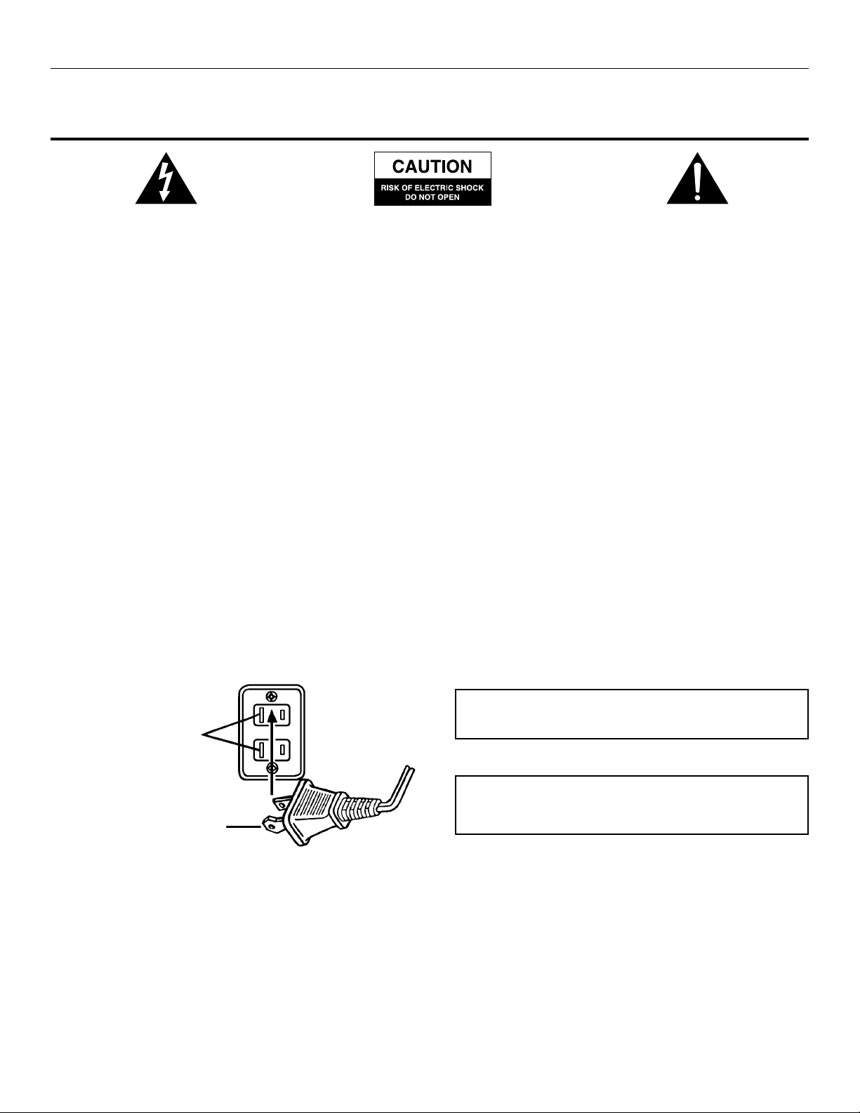
Connecting the Power Cord
AC Wall Socket
Long slot is neutral (ground) side.
Insert the wide blade into the
ground side slot.
CAUTION: To prevent electric shock do not use this (polarized) plug with
an extension cord, receptacle or other outlet unless the blades can be fully
inserted to prevent blade exposure.
WARNING
TO REDUCE THE RISK OF FIRE OR ELECTRIC SHOCK, DO NOT
EXPOSE THIS APPLIANCE TO RAIN OR MOISTURE.
Page 3
SPECIFICATIONS
System Response 20Hz – 20kHz
Total Audio Output 80 Watts
Input Impedance >10k Ohms
Analog Input Sensitivity 300mV for full output
Digital Input S/PDIF*
SATELLITE AMPLIFIED
SPEAKERS
Drivers Four 3” full range
Two 1” Tweeters
Power 40 Watts (10 watts per
driver) at .10% THD
Signal-to-Noise Ratio >70dB
SUBWOOFER
Driver One 8” dual voice coil
Power 40 watts at 1% THD
Crossover Frequency 150Hz
Signal-to-Noise Ratio >70dB
POWER REQUIREMENTS
USA/Canada 120V/240W/60Hz
Europe/United
Kingdom and various
Asian countries 230V/240W/50Hz
UL/CU/CE Approved
DIMENSIONS
Subwoofer 345mm Wide X
290mm Deep X
235mm High
Main Speakers 102mm Wide X
130mm Deep X
155mm High
Surrounds 120mm Wide X
105mm Deep X
108mm High
*Sony Philips Digital Interconnect Format
Introduction
The ADA880 is a technologically advanced multimedia amplified speaker system featuring Dolby Digital AC3 and Dolby Pro-Logic surround
sound and stereo reproduction. The amplifier inputs can simultaneously operate on analog and digital (S/PDIF)* audio signals.
The unit is comprised of a subwoofer and two satellite speakers. This combination provides surround sound on a desktop by
utilizing side firing speakers. For enhanced surround sound the top speaker portion of each satellite can be separated and placed on
a provided stand with long speaker wires. This enables the separated speakers to be placed for best surround sound performance.
Equalizer circuitry automatically resets to conform to the changes that take place when the speakers are separated.
The satellite speakers are magnetically shielded and can be placed close to a monitor without disturbing images. The speaker in the
subwoofer is not magnetically shielded and should not be placed close to a monitor.
Subwoofer frequencies are non directional, therefore, the subwoofer does not have to be located in any particular relationship to the
satellite speakers. Placing it on the floor close to a wall, corner of a room or under a desk gives excellent results.
The main satellite speaker has status indicators to show the various conditions of operation. Amaster volume control is used to
separately adjust bass, center, surround and treble settings. Once the individual functions are set, the control reverts back to
becoming a master volume control. Aremote control unit is supplied that can access all the manual functions. The remote control
has a mute function that is not available when using the controls manually.
The AC3/PRO-LOGIC/STEREO decode circuits operate automatically. If the unit is in the STEREO or PRO-LOGIC mode and an
AC3 signal appears at the input of the amplifier, the circuitry automatically switches over to AC3. This and other automatic features
are explained under “Using the Speaker System.”
If analog and digital signals appear at the input of the amplifier, the analog signal is automatically reduced in volume level.
*Sony/Philips Digital Interconnect Format.
Page 4

Setup
Do not plug the AC power plug into the wall outlet until all connections are made.
The ADA880 can be setup in two configurations. For ENHANCED SURROUND sound a 5-piece setup is used. For near field
STEREO/SURROUND sound a 3-piece setup is used. The two modes of operation are described below. The speakers are packaged
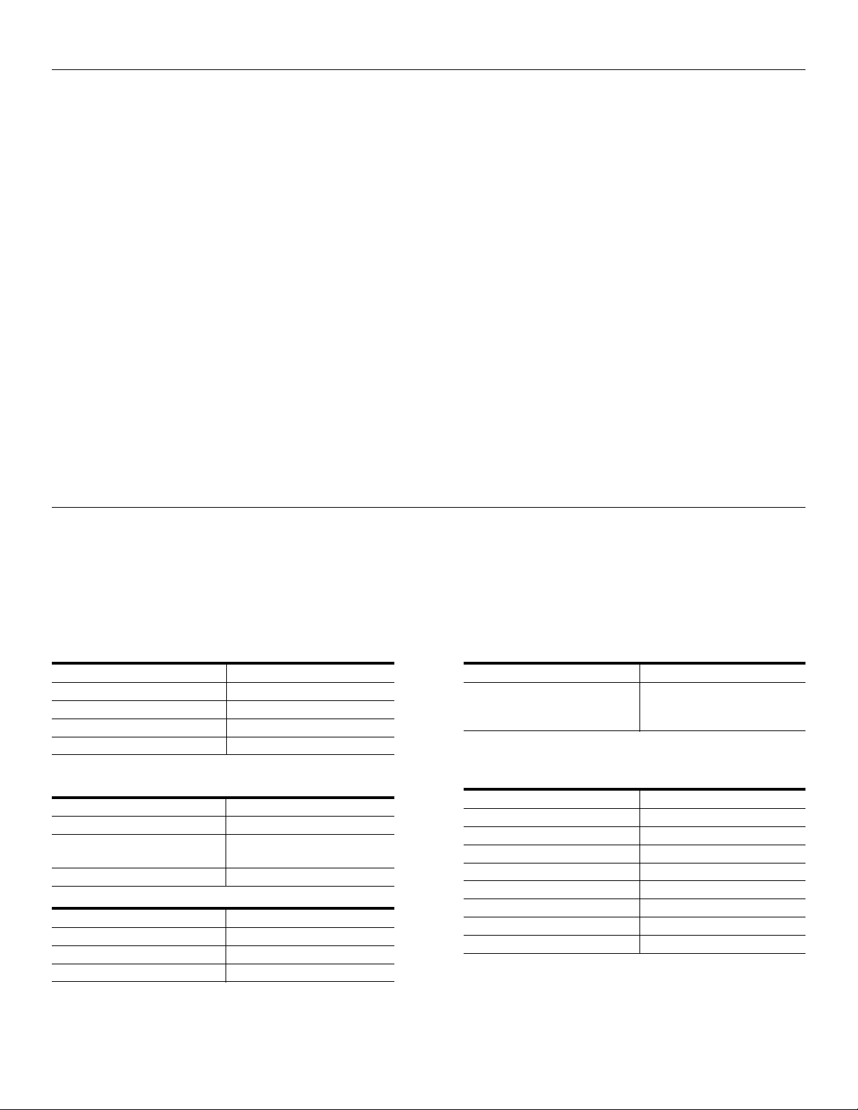
and shipped in the 5-piece arrangement. Follow the instructions and pictorial view below to make the 5-piece connections.
Enhanced Surround Sound Operation (See Figure 1)
1) Connect the left and right satellite speakers.
Notice that the DIN connectors from the left and right satellite speakers are color-coded and plug into the matching color
indicators on the back of the subwoofer. Also note that the connectors have arrows. These arrows should face up as shown
in Figure 1.
2) Connect the left and right surround speakers.
The left (yellow) and right (purple) surround speaker connectors are plugged into the corresponding colored inputs on the
back of the subwoofer.
3) Connect the subwoofer to the computer.
The green color-coded wire connects the ANALOG INPUT on the subwoofer to the AUDIO OUTPUT on the computer.
The black RCA type plug is used to connect the S/PDIF INPUT on the subwoofer to a DVD player.
4) Plug the AC power plug into the wall outlet.
The ADA880 unit should be installed close to the AC power outlet so that the power plug can be readily removed from the
outlet in the event of a hazardous problem.
Your ADA880 system is now ready for use.
Near Field Stereo/Surround Sound Operation (see Figures 2 and 3)
If it is desired to convert to a 3-speaker system, follow the instructions and the pictorial view below.
1) Separate the left and right surround speakers from their stands by gently pulling the speaker up (See Figure 2)
2) Remove the left (yellow) and right (purple) speaker wires from the subwoofer.
(Set speaker stands aside for future use)
3) Remove the supplied rubber plugs from the top of the satellite speakers.
4) Mount the surround speakers on top of the satellite speakers as shown in Figure 2.
(The connections to the satellite speakers are made automatically once the surround speakers are mounted)
The ADA880 unit should be installed close to the AC power outlet so that the power plug can be readily removed
from the outlet in the event of a hazardous problem.
Your ADA880 system is now ready for use.
Figure 1
Figure 2
Page 5
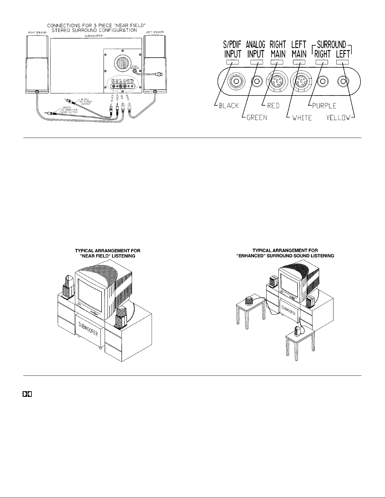
Figure 3
Figure 4
Figure 5
Placement of Speakers (See Figures 4 and 5)
All stereo information is heard from the satellite and surround speakers. The subwoofer contains no stereo information and its sound is
non-directional. As a result, the subwoofer does not necessarily have to be placed in any particular relationship to the satellites. Placing
the subwoofer on the floor close to a wall or corner of a room provides maximum bass efficiency. The subwoofer is not magnetically
shielded and should not be placed near video displays.*
Near Field
The satellite and surround speakers are magnetically shielded and can be placed close to the computer monitor without distorting video
images. Best stereo effect is obtained by placing the speakers as far apart as practical.
Enhanced Surround Sound
Best surround effect is obtained by placing the surround speakers forward of the monitor and approximately the same distance apart as
the satellite speakers. Excellent results are obtained when the surround speakers are in line with, and slightly above the listeners ears.
*Note: Care should be taken not to place diskettes or other magnetic media on the subwoofer.
Using the Speaker System (See Figure 6)
*POWER. Press this button to turn power on. Agreen indicator will glow. Press again to turn power off.
DOLBY. The DOLBY button allows 2 modes of operation – STEREO or SURROUND. Repeatedly pressing this button toggles
between the two modes.
See A) B) C) below.
A) STEREO. When the function indicator is off: the unit is in the STEREO mode.
B) SURROUND. When the function indication is amber the unit is in the SURROUND PRO-LOGIC mode.
C) DOLBY DIGITAL (AC3). When the function indicator is green: The unit is in the DOLBY DIGITAL (AC3) mode. This function
is selected automatically whenever a Dolby Digital Surround Signal is detected at the input. The automatic selection will occur
regardless of the mode of operation, STEREO or SURROUND.
*Note: If the AC source of power is turned off before the power switch is turned off on the unit a “pop” sound may be heard from
the speakers. This is normal and not a problem. To avoid the “pop” sound, turn off the unit first.
Page 6

BASS. The BASS button allows 2 modes of operation: BASS level control or CENTER level control.
See D) and E) below.
D) BASS LEVEL CONTROL. The bass level control is accessible in all modes of operation. If it is desired to increase/decrease
BASS response, press this button. The green function indicator above the control will glow. Also, the volume level indicators
will glow showing the last setting of the control. Rotate the master volume control clockwise to increase bass and counter
clockwise to decrease bass. Only 6 of the 7 level indicators are operational in this mode. As volume is increased/decreased
only one level indicator at a time will glow in ascending or descending order. As the volume control is varied and passes through
the flat response setting of the control, the 2 center indicators will glow. (This is the equivalent of a manual volume control set
at center detent indicating flat response.)
E) CENTER LEVEL MODE. This function is only operational in the SURROUND mode. Hold the BASS button depressed
until the function indicator begins flashing on/off. Rotate the master volume control clockwise to increase the center volume
and counterclockwise to decrease center volume. The green volume level indicators will glow in ascending order as volume
is increased and will turn off in descending order as volume is decreased.
TREBLE. The TREBLE button allows 2 modes of operation, TREBLE level control or SURROUND level control.
See F) and G) below.
F) TREBLE LEVEL CONTROL. The treble level control is accessible in all modes of operation. If it is desired to
increase/decrease TREBLE response, press this button, the green function indicator above the control will glow. Also, the
volume level indicators will glow showing the last setting of the control. Rotate the master volume control clockwise to increase
treble and counter clockwise to decrease treble. Only 6 of the 7 volume level indicators are operational in this mode. As volume
is increased/decreased only one level indicator at a time will glow in ascending or descending order. As the volume control
is varied and passes through the flat response setting of the control the 2 center indicators will glow. (This is the equivalent
of a manual volume control set at center detent indicating flat response.)
G) SURROUND. This function is only operational in the SURROUND mode. Hold the TREBLE button depressed until the
function indicators begin flashing on/off. Rotate the master volume control clockwise to increase the surround volume and
counter-clockwise to decrease the surround volume. The green volume indicators will glow in ascending order as volume
is increased and will turn off in descending order as volume is decreased.
MASTER VOLUME CONTROL. The MASTER VOLUME CONTROL provides two functions. It operates as a master volume
control for the overall system and can also be used to individually adjust the volume levels of BASS, CENTER, TREBLE and
SURROUND. If any one of the functions is selected and is not adjusted within a few seconds, the control reverts back to becoming
a master volume control.
FLAT RESPONSE SETTINGS. To set the BASS and TREBLE controls to a flat response (default) and the CENTER and
SURROUND controls to mid volume level positions, both the BASS and TREBLE buttons must be depressed at the same time.
Initially the function indicators above buttons the will be green. The buttons must be kept depressed until the indicators turn off.
The amplifier response is now flat (linear). If it is desired to increase/decrease BASS or TREBLE response press either of these
buttons respectively. Two volume level indicators will glow in the middle of the display indicating the flat response of the amplifier.
Notice that the volume level display has changed from 7 to 6 indicators. Rotate the volume control clockwise to increase levels and
counter-clockwise to decrease levels from the flat setting.
To access CENTER and SURROUND volume level settings, the unit must be in the SURROUND mode. Press either the BASS or
TREBLE button until the function indicator flashes. Four volume level indicators will glow showing mid setting. Adjust the
volume control clockwise to increase volume level from the mid setting and counter-clockwise to decrease volume level from the
mid setting. All volume level indicators are operational in this mode.
Figure 6
Page 7

Remote Control Operation (See Figure 7)
The remote control can perform most of the manual operations. For best performance aim the front part of the control towards the
infrared detector as shown in Figure 6. Below are listed the functions of the control.
POWER. Press this button to turn power on. The power indicator on the satellite will glow.
Press again to turn power off.
TREBLE. Press this button if it is desired to adjust the TREBLE level. The function indicator
above the TREBLE button on the satellite will glow. To increase/decrease volume, press the
up/down arrows on the VOL button. The volume level indicators will glow in ascending order
as volume is increased and will turn off in descending order as volume is decreased.
BASS. Press this button if it is desired to adjust the BASS level. The function indicator above
the BASS button on the satellite will glow. To increase/decrease volume, press the up/down
arrows on the VOL button. The volume level indicators will glow in ascending order as volume
is increased and will turn off in descending order as volume is decreased.
STEREO. Press this button to operate in the STEREO mode. The indicator above the
DOLBY button on. The satellite will be off in this mode.
MUTE. This function is only available when using the remote control. Press this button to mute
the sound. The volume level indicators will turn off. The power and function button indicators
remain on. Press this button again to restore sound.
Press any other function (except power) and sound will be restored.
CENTER. This function is only operational in the SURROUND mode. Press this button to adjust the volume level of the center
channel. The green function indicator above the BASS button on the satellite will flash on/off. Set the center level by using the
up/down volume control (VOL). The green volume indicators will glow in ascending order as volume is increased and will turn off
in descending order as volume is decreased.
SURR(SURROUND). This function is only operational in the surround mode. Press this button to adjust the volume level of the
SURROUND PRO-LOGIC mode. The green function indicator above the treble button on the satellite will flash on/off. Set the
surround level by using the up/down volume control (VOL). The green volume level indicators will glow in ascending order as
volume is increased and will turn off in descending order as volume is decreased.
DOLBY. The DOLBY button allows 2 modes of operation - STEREO or SURROUND.
(A)STEREO. When the function LED is off on the satellite, the unit is in the STEREO modes.
(B)SURROUND. When the amber function LED is on the satellite, the unit is in the surround PRO-LOGIC mode.
(C)DOLBY DIGITAL(AC3). When the function LED is green on the satellite, the unit is in the DOLBY DIGITAL (AC3) mode.
This function is selected automatically whenever a Dolby Digital surround signal is detected at the input. The automatic selection
will occur regardless of the mode of operation, STEREO or SURROUND.
Figure 7
Page 8

All indicators are off AC Cord is not connected to Connect AC power
ADA880 Troubleshooting
Symptoms Possible Problem Solution
No Sound from all Speakers Power is not on Verify the AC line cord is plugged into the wall outlet
Mute turns off unexpectedly Mute was re-pressed or a function System will un-mute whenever the mute button is pressed
Subwoofer emits very loud Signal cable is not completely Make sure cable is inserted snugly into signal jack
humming/buzzing noise inserted into signal jack on subwoofer
No sound from Subwoofer Subwoofer volume is too low Select Bass function and raise volume level
No sound from surround speakers Unit is not in a surround mode Press the mode button to select a surround mode.
Center and Surround buttons Unit is not in a surround mode Press the mode button to select a surround mode.
do not work Prologic - Amber Dolby Digital - Green
No sound from surround speakers Surround bases are not connected Connect surround bases to rear of subwoofer
when detached Unit is not in a surround mode Press the mode button to select a surround mode.
No playback from digital input Digital signal cable is not connected Connect digital signal cable to S/PDIF output
Sound is distorted Volume level too high Decrease master volume level
Not enough treble Treble setting is too low Select Treble function and increase level
Too much treble Treble setting is too high Select Treble function and decrease level
Too much bass Bass setting is too high Select Bass function and decrease level
Remote Control does not work Batteries are dead or not installed Replace or install new batteries
wall outlet
Control Speaker is not connected Connect control speaker to subwoofer
to the subwoofer
Power is off Press power button or use remote to turn on the system
Volume setting is too low Raise master volume control
S/PDIF cable is not connected Connect S/PDIF cable
to DVD playback card
Signal cable is disconnected Connect signal cable
from sound card
Right (Control) speaker is disconnected Connect right (Control) speaker
was selected again, if a function button is pressed, or if the volume control
Surround level is too low Select surround level function and raise volume
Surround level is too low Select surround level function and raise volume
Remote is not pointed at speakers Point remote control at the left side of LED bar
Remote signal path is blocked Removed any object that is blocking the signal from the remote
Verify power switch has been pressed (green Power LED is lit)
is rotated
Press and hold Treble and Bass buttons for 3 seconds to reset
Treble, Bass, Center, and Surround levels to default position.
Prologic – Amber Dolby Digital – Green
Press and hold Treble and Bass buttons for 3 seconds to reset
Treble, Bass, Center, and Surround levels to default position
Prologic - Amber Dolby Digital - Green
Press and hold Treble and Bass buttons for 3 seconds to reset
Treble, Bass, Center, and Surround levels to default position
of DVD playback card
Press and hold Treble and Bass buttons for 3 seconds to reset
Treble, Bass, Center, and surround levels to default position
Press and hold Treble and Bass buttons for 3 seconds to reset
Treble, Bass, Center, and surround levels to default position
Press and hold Treble and Bass buttons for 3 seconds to reset
Treble, Bass, Center, and surround levels to default position
to the left side of the LED bar
 Loading...