

Page 1

User Guide Altec Lansing
Computer Speaker System
Mode d’emploi Altec Lansing
Système d’enceintes acoustiques pour
ordinateur
Manual del usuario Altec Lansing
Sistema de altavoces para ordenador
Manuale per l’uso Altec Lansing
Sistema di altoparlanti per computer
Benutzerhandbuch Altec Lansing
Computer-Lautsprechersystem
ACS56
www.altecmm.com
© 2000 Altec Lansing Technologies, Inc., Milford, PA 18337-0277
800-ALTEC-88
Page 2

IMPORTANT
The lightning flash with arrowhead, within an equilateral
triangle, is intended to alert the user to the presence of
uninsulated “dangerous voltage” within the product’s
enclosure that may be of sufficient magnitude to
constitute a risk of electric shock to persons.
Read Instructions — All the safety and operating instructions
should be read before the appliance is operated.
Retain Instructions — The operating instructions should be
retained for future reference.
Heed Warning — All warnings on the appliance and in the operating
instructions should be adhered to.
CAUTION: TO PREVENT THE RISK OF ELECTRIC SHOCK, DO NOT
REMOVE COVER (OR BACK). NO USER-SERVICEABLE PARTS INSIDE.
REFER SERVICING TO QUALIFIED SERVICE PERSONNEL.
SAFETY INSTRUCTIONS
• The appliance does not appear to operate normally or exhibits a
marked change in performance.
• The appliance has been dropped or the enclosure damaged.
Servicing — The user should not attempt to service the appliance.
Servicing should be referred to qualified service personnel or returned
to the dealer or call the Altec Lansing service line for assistance.
The exclamation point within an equilateral triangle is
intended
to alert the user to the presence of important
operating and maintenance (servicing) instructions in
the literature accompanying the appliance.
Follow Instructions — All operating and use instructions should be
followed.
Water and Moisture — The appliance should not be used near water
– for example, near a bathtub, washbowl, kitchen sink, laundry tub, in
a wet basement, or near a swimming pool, etc.
CAUTION
To prevent electric shock do not use this (polarized)
plug with an extension cord, receptacle or other outlet
unless the blades can be fully inserted to prevent blade
Outdoor Use — Warning: To reduce the risk of fire or electric shock,
do not expose this appliance to rain or moisture.
Location — The appliance should be installed in a stable location.
Ventilation — The appliance should be situated so that its location or
position does not interfere with its proper ventilation. For example,
WARNING
TO REDUCE THE RISK OF FIRE OR ELECTRIC SHOCK, DO
NOT EXPOSE THIS APPLIANCE TO RAIN OR MOISTURE.
the appliance should not be situated on a bed, sofa, rug, or similar
surface that may block the ventilation openings; or placed in a built-in
installation, such as a closed bookcase or cabinet that may impede the
flow of air through the ventilation openings.
Heat — The appliance should be situated away from heat sources such
as radiators, heat registers, stoves, or other appliances (including
amplifiers) that produce heat.
Power Sources — The appliance should be connected to a power
supply only of the type described in the operating instructions or as
marked on the appliance.
Power-Cord Protection — Power-supply cords should be routed so
that they are not likely to be walked on or pinched by items placed upon
or against them. Pay particular attention to cords at plugs, convenience
receptacles, and the point where they exit from the appliance.
Grounding or Polarization — The precautions that should be taken
so that the grounding or polarization means of an appliance is not
defeated.
Cleaning — The appliance should be cleaned only with a polishing cloth
or a soft dry cloth. Never clean with furniture wax, benzine,
insecticides or other volatile liquids since they may corrode the
cabinet.
Non-Use Periods — The power cord of the appliance should be
unplugged from the outlet when left unused for a long period of time.
Object and Liquid Entry — Care should be taken so that objects do
not fall and
liquids are not spilled into the enclosure through openings.
Damage Requiring Service — The appliance should be serviced by
qualified
service personnel when:
• The power-supply cord or the plug has been damaged.
• Objects have fallen, or liquid has been spilled into the appliance.
• The appliance has been exposed to rain.
3
Page 3

Figure
1
TYPICAL SPEAKER ARRANGEMENT FOR
GAMING SPATIAL SOUND EFFECTS
Disposition spatiale typique des haut-parleurs pour les effets
acoustiques des jeux vidéo
Configuración típica de los altavoces para efectos de sonido
espaciales en los juegos
Tipica posizione degli altoparlanti per ottenere effetti sonori e spaziali
per giochi multimediali
Typische Lautsprecheranordnung für räumliche Klangeffekte bei
Spielanwendungen.
Connecting the Power Cord
AC Wall Socket
Long slot is neutral
(ground) side.
Insert the wide blade into the
ground side slot.
The FCC Wants You to Know
This equipment has been tested and found to comply with the
limits for a Class B digital device, pursuant to Part 15 of the
FCC rules. These limits are designed to provide reasonable
protection against harmful interference in a residential
installation. This equipment generates, uses and can radiate
radio frequency energy and, if not installed and used in
accordance with the instructions, may cause harmful
interference to radio communications. However, there is no
guarantee that intererence will not occur in a particular
installation. If this equipment does cause harmful interference
to radio or television reception, which can be determined by
turning the equipment off and on, the user is encouraged to try
to correct the interference by one or more of the following
measures:
Verbindungskabel (Dongle) zum Verbinden des Computerausgangs mit dem
S/PDIF-Kabel eingeschlossen. Einige Soundkarten haben evtl. keinen
hinteren analogen oder S/PDIF-Ausgang. Informationen über Ihre
spezifische Soundkarte finden Sie in der Gebrauchsanleitung Ihres
Computers.
Note: The supplied S/PDIF connection cable is terminated
with RCA type plugs. In some instances, this type of plug
may not match the corresponding sound card. A
connector cable (Dongle) is provided that will match the
computer output and the S/PDIF cable. Some sound cards
may not have a rear analog or S/PDIF output. Refer to
your computer instruction manual for information on the
sound card used in your model.
NOTE: Le câble de connection IFN S/P (Interface
numérique Sony /Philips) se termine par des prises de
type RCA. Dans certains cas, il se peut que ces dernières
ne correspondent pas à la carte son. Un câble de
connection (Dongle) est fourni pour adapter la sortie de
l’ordinateur au câble IFN S/P. Il est possible que certaines
cartes son ne soient pas équipées d’une sortie analogique
ou IFP S/P. Vous reporter au manuel d’utilisation de votre
ordinateur pour toute information sur la carte son utilisée
sur votre modèle.
NOTA: El cable de conexión S/PDIF termina con enchufes
tipo RCA. En algunos casos, este tipo de enchufe podría
no adaptarse a la tarjeta de sonido correspondiente. Se
proporciona un cable de conexión (Dongle) para adaptar
la salida del ordenador y el cable S/PDIF. Algunas tarjetas
de sonido podrían no tener una salida posterior analógica
o S/PDIF. Remítase al manual de instrucciones del
ordenador para obtener información sobre la tarjeta de
sonido utilizada en su modelo.
NOTA: Il cavo fornito di collegamento S/PDIF termina con
spine di tipo RCA. In qualche caso, questo tipo di spina
potrebbe non adattarsi alla corrispondente scheda sonora.
Viene fornito un cavo di collegamento (Dongle) che si
adatterà all’uscita del computer e al cavo S/PDIF. Alcune
schede sonore potrebbero non avere un’uscita posteriore
analogica o S/PDIF. Fare riferimento al manuale di
istruzioni del proprio computer per avere informazioni
sulla scheda sonora usata nel proprio modello.
HINWEIS: Das gelieferte S/PDIF-Verbindungskabel ist mit
a) Reorient or relocate the receiving antenna.
Steckern des Typs RCA bestückt. In einigen Fällen können diese Stecker nicht mit der
entsprechenden Soundkarte verwendet werden. Im Lieferumfang ist deswegen ein
54
Page 4
1 Vue arrière de l'ACS56 montrant les connexions
2 Haut-parleur satellite ambiophonique gauche
3 Haut-parleur satellite avant gauche
4 Les tensions secteur et les prises de courant
varient selon le pays de destination de ce produit
5 Subwoofer
6 Haut-parleur satellite avant droit (actif)
7 Haut-parleur satellite stéréophonique droit
8 Connexion numérique jaune
9 Entrée de ligne avant
10 Entrée ambiophonique noire
11 Connexion avant droit orange
12 Connexion avant gauche marron
13 Connexion ambiophonique gauche dorée
14 Connexion ambiophonique droit mauve
15 Bouton marche/arrêt
16 Vers sortie numérique ordinateur
17 Vers sortie avant ordinateur
18 Vers sortie ambiophonique ordinateur
19 Dongle
1 Vista posterior del ACS56 indicando las
conexiones
2 Altavoz satélite izquierdo circundante
3 Altavoz satélite izquierdo frontal
4 El enchufe de alimentación y los voltajes de la
línea
cambiarán según el país al que se envíe el
producto
5 Subaltavoz de graves
6 Altavoz satélite derecho (activo) frontal
7 Altavoz satélite derecho circundante
8 Frontal digital, amarillo
9 Entrada frontal, lima
10 Entrada circundante, negra
11 Frontal derecho, anaranjado
12 Frontal izquierdo, marrón
13 Circundante izquierdo, amarillo oro
14 Circundante derecho, morado
15 Botón de encendido y apagado
16 A la salida digital del ordenador
17 A la salida frontal del ordenador
18 A la salida circundante del ordenador
19 Dongle
1 ACS56 Rückansicht - Verbindungsschema
2 Linke Surround-Satellitenbox
3 Linke vordere Satellitenbox
4 Die jeweiligen Netzstecker und Netzspannungen
hängen vom
jeweiligen Auslieferungsland ab
5 Subwoofer
6 Rechte vordere (Aktiv-)Satellitenbox
7 Rechte Surround-Satellitenbox
8 Gelb, digital, vorne
9 Grün, Eingang, vorne
10 Schwarz, Eingang, Surround
11 Orange, vorne, rechts
12 Braun, vorne, links
13 Gold, Surround, links
14 Lila, Surround, rechts
15 Netzschalter
16 Zu digitalem Computer-Ausgang
17 Zu vorderem Computerausgang
18 Zu Computer-Surround-Ausgang
19 Dongle
b) Increase the separation between the equipment and
receiver.
c) Connect the equipment to an outlet on a circuit different
from that to which the receiver is connected.
d) Consult the dealer or an experienced radio/TV technician
for help.
FCC Warning
Modifications not expressly approved by the manufacturer
could void the user authority to operate the equipment under
FCC Rules.
All stereo and surround sound is processed from the
satellite speakers. Subwoofer frequencies are monaural
and contain no stereo or surround information. As a
result, the subwoofer does not have to be placed in any
particular relationship to the satellite speakers. The
subwoofer is not magnetically shielded and should not
be placed near the monitor. Placing the subwoofer on the
floor close to a wall, corner of a room or under a desk
gives excellent results. Figure 1 shows a typical
Introduction
The ACS56 is especially designed as a “Gaming”
amplified speaker system. The input signals to operate
the speakers are obtained from a multimedia computer
with a gaming “sound” card. The ACS56 can also operate
from a stereo sound card. However, in this instance
only stereo operation of the speakers is possible.
The ACS56 consists of four satellite speakers and a
subwoofer. The satellite speakers are magnetically
shielded and can be placed close to the computer monitor
without distorting color or images. The subwoofer is not
magnetically shielded and should not be placed close to
the monitor.
arrangement of the speakers for best stereo and spatial
affects.
Setup Instructions (See Figure 2)
Do not insert the power plug into an AC outlet
until all connections are made.
Notice that the input jacks on the subwoofer are color
coded to prevent errors. The plugs that are inserted into
these jacks have matching colors. As an example, the
left front speaker satellite has a brown connecting plug.
The plug is inserted into the brown color strip under the
left front jack marking. All other connections are made
in the same way. A DIN plug is used to make the
connections for the right front satellite speaker. Note
that the DIN plug has
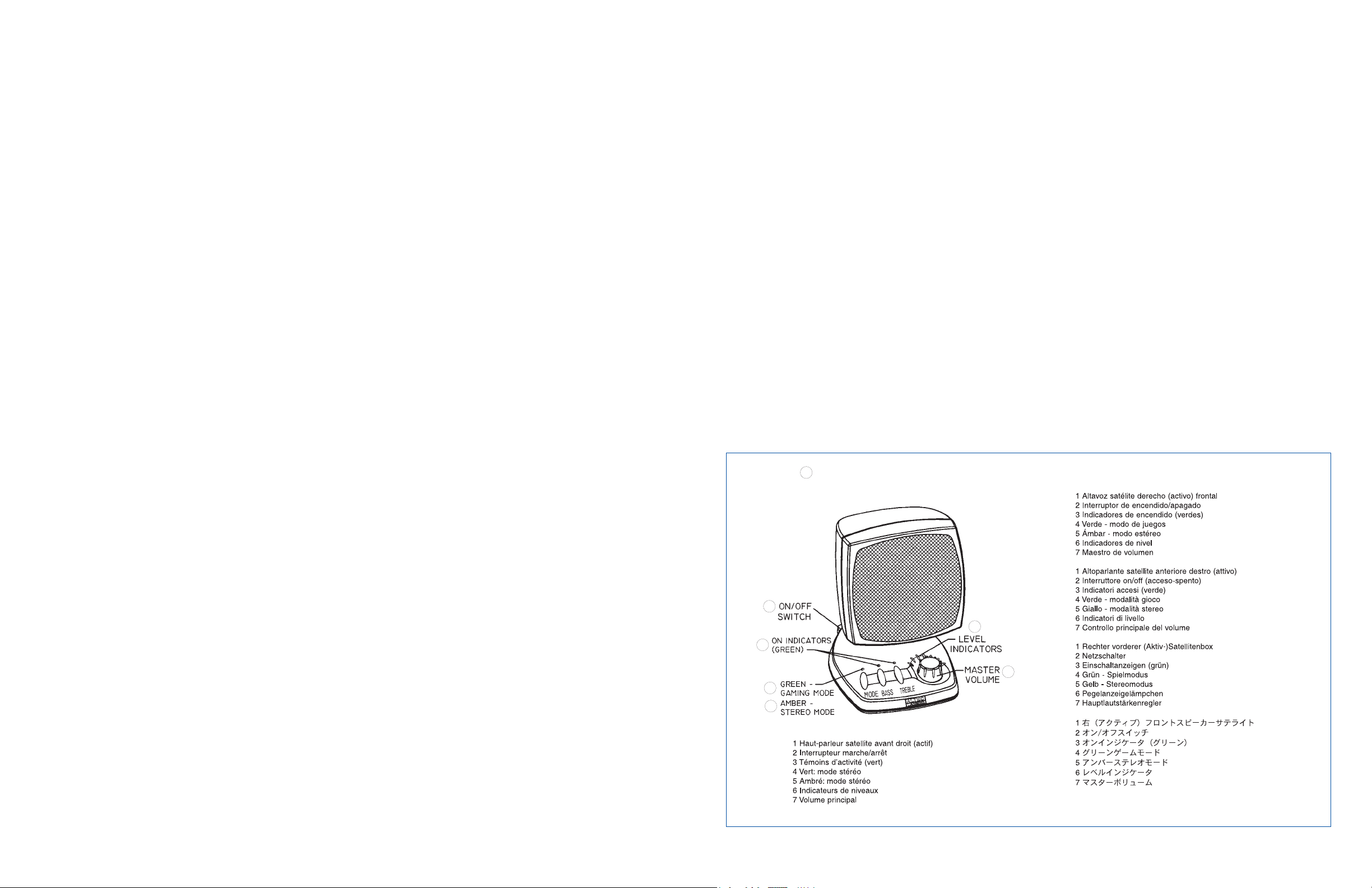
Figure
3
1
RIGHT (ACTIVE) FRONT
SPEAKER SATELLITE
1 Diagramma con vista posteriore dello ACS56 che
mostra i collegamenti
2 Altoparlante satellite sinistro surround
3 Altoparlante satellite anteriore sinistro
4 La spina di alimentazione e la tensione di linea
cambiano in base ai paesi in cui sarà spedito il
prodotto
5 Subwoofer
6 Altoparlante satellite anteriore destro (attivo)
7 Altoparlante satellite destro surround
8 Giallo anteriore digitale
9 Immissione anteriore verde
10 Immissione surround nera
11 Arancione anteriore destro
12 Marrone anteriore sinistro
13 Giallo oro sinistro surround
14 Viola destro surround
15 Pulsante On/ Off (acceso-spento)
16 All'emissione digitale del computer
17 All'emissione anteriore del computer
18 All'emissione surround del computer
19 Dongle
2
6
3
7
4
5
76
Page 5

an arrow. The arrow should face up for easy insertion
into the
DIN jack.
Computer gaming sounds cards have three outputs. Most
usually, the outputs will be marked as Digital output,
Front output and Surround output. Some slightly
different terminology may be used. However, the sound
card instructions will provide information so that you
can determine what the outputs are. Connect the ACS56
three inputs to the computer sound card.
Stereo Operation. If your computer only has a stereo
sound card, the ACS56 will still provide excellent
performance. In this instance the sound card stereo
output should be connected to the Front speaker input.
Both Front/Surround speakers will be operational. The
front and surround speakers in the left channel will
perform as the left surround stereo channel and the
right front and rear speakers will be the stereo right
channel. The mode button should be in stereo function.
Insert the power plug into an AC outlet. The unit is now
ready to be operational.
Operation of the controls (See Figure 3)
On/Off Switch. The on/off switch is located on the
rear of the right satellite speaker. Press this switch to
turn the unit on, the Mode indicator will light to show
power is on. Press the switch again to turn power off.
Operation any of the functions will also turn the unit on.
In this instance, to turn the unit off, press the On/Off
switch.
Master Volume Control. The master volume control
has several functions. It operates as a master volume
control for the overall system and can be used to
individually adjust the levels of Bass, Treble, or
Surround sound. If any of these functions is selected and
not used for a few seconds, the control reverts back to
becoming a master volume control.
Seven level indicators around the control show the
position of the control. In the extreme counter-clock
position all LEDs are off. As the control is rotated
clockwise the LEDs illuminate one at a time until in the
maximum position, all LEDs are on.
If one of the functions buttons has been depre ssed (BASS
or TREBLE), the master level rotary control will adjust
the level of the function selected. In this mode, the green
function indicator associated with the function will be
illuminated: see TREBLE/BASS CONTROLS below.
Treble/Bass Controls. To raise or lower the treble
or bass response, press the switch next to each mode
selector, a green indicator will glow to show the
function is operational. Turn the ROTARY control
clockwise to increase response and counterclockwise to
decrease response. Once the level is set, the indicator
next to the function will turn off after a short period.
Each function can be turned off quickly by pressing the
function button a second time. To reset the Treble and
Bass controls to the factory preset (flat) position,
depress and hold the corresponding button for a period of
approximately three seconds. The green indicator will
go out denoting the control has been reset. Once the green
indicator is off, the master volume control becomes
operational.
Mode Selector. The LED indicator above the Mode
switch can operate in two colors, Green and Amber. By
pressing the Mode switch repeatedly, the mode of
operation can change from Stereo
to the “Gaming” mode. When the LED is green the
ACS56 is in
the Gaming mode and when the LED is amber, the unit is
in the stereo mode.
Surround Channel Volume Level Adjustments.
To adjust the volume level of the surround speakers, in
either the stereo or gaming mode, hold down the Mode
button until the level indi-cators around the Master
Volume Control flash On/Off. The flashing LEDs indicate
that the master volume control is programmed to adjust
the level of the rear speakers. If the control is not
actively used for a short while, the control reverts back
to becoming a master volume control.
Placement of Speakers
Some experimentation may be required to obtain the
best sound effects in your particular room environment.
The subwoofer achieves maximum efficiency when
placed on the floor and close to a wall or corner of a
room. In this instance the walls behave as an extension
of a speaker horn. The subwoofer is not shielded and
should not be placed near the monitor. The front
satellites can be close to the monitor or stretched out as
far as the speaker cords allow. The placement depends
on where the listener sits. The surround speakers can be
placed slightly behind the listener or as far as the
speaker cords allow. Most usually the speakers are
placed at ear level or slightly above. The surround
speaker stands contain notches for mounting the
surround speakers to a wall with screws, if desired.
Sound effects may vary depending on how the recordings
are made. By re- arranging the speakers from time to
time the listener will become aware which arrangement
gives best results.
Specifications
System Response 30Hz — 20KHz
Total Audio Power 70 Watts
Inputs Digital
Front Speakers
Surround Speakers
Satellite Amplified Speakers
Speaker Drivers Four 3" (75mm) Full Range
Magnetically Shielded
Audio Power 35 Watts
Subwoofer
Speaker Driver Long Throw 6 1/2"
(165mm)
Audio Power 35 Watts
Crossover Frequency 105Hz
Power Requirements
USA/Canada 120Volts 60Hz AC
Europe/United Kingdom 230Volts 50Hz AC
And various Asian Countries
ETL/cETL/CE Approved
One Year Limited Warranty
Altec Lansing Technologies, Inc. warrants to the end user
that all of its computer speaker systems are free from
defects in material and workmanship in the course of
normal and reasonable use for a term of one year from
the date of purchase.
This warranty is the exclusive and only warranty in
effect relative to Altec Lansing computer speaker
systems and any other warranties, either expressed or
implied, are invalid. Neither Altec Lansing
Technologies, Inc. nor any authorized Altec Lansing
Technologies, Inc. reseller is responsible for any
incidental damages incurred in the use of the speakers.
(This limitation of incidental or consequential damage
is not applicable where prohibited.)
Altec Lansing Technologies, Inc.’s obligation under this
warranty does not apply to any defect, malfunction or
failure as a result of misuse, abuse, improper
installation, use with faulty or improper equipment or
the use of the computer speaker systems with any
equipment for which they were not intended.
The terms of this warranty apply only to computer
speaker systems when such speakers are returned to the
respective authorized Altec Lansing Technologies, Inc.
reseller where they were purchased.
Under the terms of this warranty the original consumer
purchaser has certain legal rights and may have other
rights which vary worldwide.
Introduction
L’ACS56 est un système de haut-parleurs
amplificateurs spécial « jeux vidéo ». Les signaux
d’entrée qui excitent les haut-parleurs sont fournis par
un ordinateur multimédia à l’aide d’une carte sonore de
jeu. L’ACS56 peut également fonctionner à partir d’une
carte de son stéréo, mais dans ce cas, seules les
opérations stéréophoniques des haut-parleurs sont
possibles.
L’ACS56 comprend quatre haut-parleurs satellites et
un caisson d'extrêmes graves (subwoofer). Les hautparleurs satellites sont protégés par un blindage
antimagnétique ; ils peuvent donc être placés à
proximité d’un moniteur sans entraîner de distorsion de
couleurs ou d’images. Le subwoofer n’est pas doté d'une
protection antimagnétique ; il ne doit pas être placé à
proximité d’un moniteur.
Tous les sons ambiophoniques et stéréophoniques sont
diffusés des haut-parleurs satellites. Les subwoofers
présentent des fréquences monoauriculaires, qui ne
contiennent pas d’informations stéréophoniques ou
98
Page 6

an arrow. The arrow should face up for easy insertion
into the
DIN jack.
Computer gaming sounds cards have three outputs. Most
usually, the outputs will be marked as Digital output,
Front output and Surround output. Some slightly
different terminology may be used. However, the sound
card instructions will provide information so that you
can determine what the outputs are. Connect the ACS56
three inputs to the computer sound card.
Stereo Operation. If your computer only has a stereo
sound card, the ACS56 will still provide excellent
performance. In this instance the sound card stereo
output should be connected to the Front speaker input.
Both Front/Surround speakers will be operational. The
front and surround speakers in the left channel will
perform as the left surround stereo channel and the
right front and rear speakers will be the stereo right
channel. The mode button should be in stereo function.
Insert the power plug into an AC outlet. The unit is now
ready to be operational.
Operation of the controls (See Figure 3)
On/Off Switch. The on/off switch is located on the
rear of the right satellite speaker. Press this switch to
turn the unit on, the Mode indicator will light to show
power is on. Press the switch again to turn power off.
Operation any of the functions will also turn the unit on.
In this instance, to turn the unit off, press the On/Off
switch.
Master Volume Control. The master volume control
has several functions. It operates as a master volume
control for the overall system and can be used to
individually adjust the levels of Bass, Treble, or
Surround sound. If any of these functions is selected and
not used for a few seconds, the control reverts back to
becoming a master volume control.
Seven level indicators around the control show the
position of the control. In the extreme counter-clock
position all LEDs are off. As the control is rotated
clockwise the LEDs illuminate one at a time until in the
maximum position, all LEDs are on.
If one of the functions buttons has been depre ssed (BASS
or TREBLE), the master level rotary control will adjust
the level of the function selected. In this mode, the green
function indicator associated with the function will be
illuminated: see TREBLE/BASS CONTROLS below.
Treble/Bass Controls. To raise or lower the treble
or bass response, press the switch next to each mode
selector, a green indicator will glow to show the
function is operational. Turn the ROTARY control
clockwise to increase response and counterclockwise to
decrease response. Once the level is set, the indicator
next to the function will turn off after a short period.
Each function can be turned off quickly by pressing the
function button a second time. To reset the Treble and
Bass controls to the factory preset (flat) position,
depress and hold the corresponding button for a period of
approximately three seconds. The green indicator will
go out denoting the control has been reset. Once the green
indicator is off, the master volume control becomes
operational.
Mode Selector. The LED indicator above the Mode
switch can operate in two colors, Green and Amber. By
pressing the Mode switch repeatedly, the mode of
operation can change from Stereo
to the “Gaming” mode. When the LED is green the
ACS56 is in
the Gaming mode and when the LED is amber, the unit is
in the stereo mode.
Surround Channel Volume Level Adjustments.
To adjust the volume level of the surround speakers, in
either the stereo or gaming mode, hold down the Mode
button until the level indi-cators around the Master
Volume Control flash On/Off. The flashing LEDs indicate
that the master volume control is programmed to adjust
the level of the rear speakers. If the control is not
actively used for a short while, the control reverts back
to becoming a master volume control.
Placement of Speakers
Some experimentation may be required to obtain the
best sound effects in your particular room environment.
The subwoofer achieves maximum efficiency when
placed on the floor and close to a wall or corner of a
room. In this instance the walls behave as an extension
of a speaker horn. The subwoofer is not shielded and
should not be placed near the monitor. The front
satellites can be close to the monitor or stretched out as
far as the speaker cords allow. The placement depends
on where the listener sits. The surround speakers can be
placed slightly behind the listener or as far as the
speaker cords allow. Most usually the speakers are
placed at ear level or slightly above. The surround
speaker stands contain notches for mounting the
surround speakers to a wall with screws, if desired.
Sound effects may vary depending on how the recordings
are made. By re- arranging the speakers from time to
time the listener will become aware which arrangement
gives best results.
Specifications
System Response 30Hz — 20KHz
Total Audio Power 70 Watts
Inputs Digital
Front Speakers
Surround Speakers
Satellite Amplified Speakers
Speaker Drivers Four 3" (75mm) Full Range
Magnetically Shielded
Audio Power 35 Watts
Subwoofer
Speaker Driver Long Throw 6 1/2"
(165mm)
Audio Power 35 Watts
Crossover Frequency 105Hz
Power Requirements
USA/Canada 120Volts 60Hz AC
Europe/United Kingdom 230Volts 50Hz AC
And various Asian Countries
ETL/cETL/CE Approved
One Year Limited Warranty
Altec Lansing Technologies, Inc. warrants to the end user
that all of its computer speaker systems are free from
defects in material and workmanship in the course of
normal and reasonable use for a term of one year from
the date of purchase.
This warranty is the exclusive and only warranty in
effect relative to Altec Lansing computer speaker
systems and any other warranties, either expressed or
implied, are invalid. Neither Altec Lansing
Technologies, Inc. nor any authorized Altec Lansing
Technologies, Inc. reseller is responsible for any
incidental damages incurred in the use of the speakers.
(This limitation of incidental or consequential damage
is not applicable where prohibited.)
Altec Lansing Technologies, Inc.’s obligation under this
warranty does not apply to any defect, malfunction or
failure as a result of misuse, abuse, improper
installation, use with faulty or improper equipment or
the use of the computer speaker systems with any
equipment for which they were not intended.
The terms of this warranty apply only to computer
speaker systems when such speakers are returned to the
respective authorized Altec Lansing Technologies, Inc.
reseller where they were purchased.
Under the terms of this warranty the original consumer
purchaser has certain legal rights and may have other
rights which vary worldwide.
Introduction
L’ACS56 est un système de haut-parleurs
amplificateurs spécial « jeux vidéo ». Les signaux
d’entrée qui excitent les haut-parleurs sont fournis par
un ordinateur multimédia à l’aide d’une carte sonore de
jeu. L’ACS56 peut également fonctionner à partir d’une
carte de son stéréo, mais dans ce cas, seules les
opérations stéréophoniques des haut-parleurs sont
possibles.
L’ACS56 comprend quatre haut-parleurs satellites et
un caisson d'extrêmes graves (subwoofer). Les hautparleurs satellites sont protégés par un blindage
antimagnétique ; ils peuvent donc être placés à
proximité d’un moniteur sans entraîner de distorsion de
couleurs ou d’images. Le subwoofer n’est pas doté d'une
protection antimagnétique ; il ne doit pas être placé à
proximité d’un moniteur.
Tous les sons ambiophoniques et stéréophoniques sont
diffusés des haut-parleurs satellites. Les subwoofers
présentent des fréquences monoauriculaires, qui ne
contiennent pas d’informations stéréophoniques ou
98
Page 7

ensuite opérationnels. Les haut-parleurs avant et
ambiophonique dans le canal gauche fonctionnent alors
comme canal stéréo-ambiophonique gauche, et les hautparleurs arrière et avant droits comme canal stéréo
droit. Le bouton de mode doit être réglé sur la fonction
stéréo.
Enfoncer la fiche d’alimentation dans la prise secteur.
Le système est maintenant prêt à fonctionner.
Fonctionnement des réglages (voir figure 3)
Interrupteur marche/arrêt. L’interrupteur
marche/arrêt est derrière le haut-parleur satellite
droit. Appuyer dessus pour mettre le système sous
tension. Le voyant du mode s’allume pour indiquer que le
système est en marche. Pour mettre le système hors
tension, appuyer à nouveau sur l’interrupteur.
L’utilisation de l’une des fonctions met également le
système sous tension. Dans cet exemple, appuyer sur
l’interrupteur marche/arrêt pour mettre le système
hors tension.
Réglage de volume principal. Le bouton du volume
principal possède plusieurs fonctions. Il fonctionne
comme commande de volume principal pour l’ensemble
du système et il permet de régler séparément les
niveaux des graves, des aigus ou du son ambiophonique.
Si l’une de ces trois fonctions est sélectionnée sans être
utilisée pendant plusieurs secondes, la commande
reprend son état de bouton de réglage du volume
principal.
Sept indicateurs de niveaux sont disposés autour du
bouton pour indiquer la position du réglage. Dans la
position extrême du sens anti-horaire, tous les voyants
électroluminescents sont éteints. Quand on tourne le
bouton de réglage dans le sens horaire, les voyants
s’allument l’un après l’autre, jusqu’à la position
maximum où tous les voyants sont allumés.
Quand l’un des boutons de fonction est activé [BASS
(graves) ou TREBLE (aigus)], le bouton rotatif du
réglage ajuste le niveau de la fonction choisie. Dans ce
mode, le témoin vert associé à la fonction s’allume ; voir
la section RÉGLAGE DES AIGUS ET DES GRAVES cidessous.
Réglage des aigus et des graves. Appuyer sur le
bouton de sélection correspondant pour augmenter ou
diminuer la réponse des aigus ou des graves. Le témoin
vert s’allume pour indiquer que la fonction est
opérationnelle. Tourner le bouton du volume principal
dans le sens horaire, pour accentuer les aigus, et dans le
sens anti-horaire pour les diminuer. Une fois le niveau
réglé, l’indicateur lié à la fonction s’éteint après un
court instant. Chaque fonction peut être désactivée
rapidement en appuyant une nouvelle fois sur son
bouton. Pour rétablir les réglages par défaut définis en
usine pour les graves et les aigus, c’est la position
neutre, appuyer et maintenir enfoncé le bouton voulu
pendant environ trois secondes. Le témoin vert s’éteint
pour indiquer la restauration du réglage. Une fois le
voyant éteint, le bouton de réglage du volume principal
est à nouveau opérationnel.
Sélection du mode. L e témoin électroluminescent audessus du sélecteur de mode fonctionner en deux
couleurs : vert ou ambré. Basculer entre le mode de «
jeux vidéo » et le mode stéréo en appuyant plusieurs fois
sur ce sélectionneur. Quand le voyant est vert, l’ACS56
est en mode de jeu, et quand il est ambré, le système est
en mode stéréophonique.
Réglage du volume du canal ambiophonique.
Pour régler le volume des haut-parleurs
ambiophoniques en mode jeu ou stéréo, maintenir le
bouton du mode jusqu’à ce que les indicateurs de niveaux
s’allument et s’éteignent alternativement sur le cadran
du volume principal. Le clignotement des voyants
indique que le bouton de réglage est prêt à ajuster le
niveau des haut-parleurs arrières. Si le bouton n’est
pas utilisé pendant un bref moment, il reprend son état
de bouton de réglage du volume principal.
Positionnement des haut-parleurs
Il est conseillé d’effectuer des essais pour obtenir le
meilleur effet acoustique pour l'environnement d’écoute
particulier. Placer le subwoofer sur le sol à proximité
d'un mur ou dans le coin d’une pièce pour obtenir des
performances optimales. Les murs ont alors un effet
amplificateur. Le subwoofer n’a pas de blindage
antimagnétique ; il ne doit pas être placé à proximité de
l’écran vidéo. Les satellites avant peuvent être installés
à proximité du moniteur ou aussi loin que le permet la
longueur des cordons des haut-parleurs. Le
positionnement des haut-parleurs doit tenir compte de
la position du siège d’écoute. Les haut-parleurs
ambiophoniques peuvent être installés légèrement
derrière l’auditeur, ou aussi loin que le permet la
longueur des cordons. On obtient généralement les
meilleurs résultats quand les haut-parleurs
ambiophoniques sont alignés au niveau des oreilles ou
légèrement surélevés pour l’écoute. Les enceintes des
haut-parleurs stéréo sont munies de rainures ce qui
permet de les accrocher sur un mur à l’aide de vis si
cela est souhaité. La qua- lité des effets acoustiques peut
varier selon la qualité des enre- gistrements. En
réorganisant la disposition des haut-parleurs de temps
à autre, l’utilisateur finira par reconnaître
l’agencement qui lui apportera les résultats les plus
satisfaisant.
Spécifications
Réponse du système 30Hz — 20KHz
Sortie audio totale 70 Watts
Entrées Numériques
Haut-parleurs avant
Haut-parleurs ambiophoniques
Haut-parleurs amplificateurs satellites
Attaqueurs quatre unités 75 mm (3 pouces),
pleine gamme, à blindage
magnétique
Puissance 35 Watts
Subwoofer
Attaqueur à bobine longue portée de 165 mm
(6,5 pouces)
Puissance 35 Watts
Fréquence de coupure 105Hz
Alimentation nécessaire
Canada/États-Unis 120Volts 60Hz CA
Europe/Royaume-Uni et 230Volts 50Hz CA
divers pays d’Asie
Agréé ETL/cETL/CE
Garantie limitée d’un an
Altec Lansing Technologies garantit auprès de
l’utilisateur final tous ses systèmes acoustiques
d'ordinateur contre tout défaut de fabrication ou de main
d’oeuvre, pour autant qu'un usage normal et raisonnable
en soit fait et ce pendant une période d’un an à compter
de la date d'achat.
Cette garantie exclusive sera la seule garantie en
vigueur relative aux systèmes acoustiques d’ordinateur
Altec Lansing, et toutes les autres garanties, expresse ou
implicite, ne sont pas valides. Altec Lansing
Technologies, Inc. et ses revendeurs agréés déclinent
toute responsabilité quant aux dommages accessoires qui
résulteraient de l’utilisation des haut-parleurs. (Cette
limitation des dommages accessoires et fortuits n’est
pas applicables dans les pays qui interdisent de telles
lois).
L’obligation de garantie de Altec Lansing Inc. ne
s’applique pas aux anomalies, aux défauts de
fonctionnement ou aux pannes qui résulteraient de
produits malmenés, négligés, endommagés à la suite
d’une installation impropre, ou reliés à des équipements
défectueux ou inadaptés, ou si les systèmes acoustiques
d’ordinateur sont utilisés avec des équipements pour
lesquels ils ne sont pas prévus.
Les termes de cette garantie s’appliquent aux systèmes
acoustiques d’ordinateur Altec Lansing quand les hautparleurs sont renvoyés auprès du revendeur agréé Altec
Lansing Technologies, Inc qui les a vendus.
Aux termes de cette garantie, l’acheteur initial dispose
de certains droits : la législation du pays ou de l’état peut
lui en accorder d’autres.
Introducción
El ACS56 es un sistema de altavoces amplificado especial
para “juegos”. Las señales que entran a los altavoces
provienen de un ordenador multimedia que tiene una
tarjeta de sonido para juegos. El ACS56 puede funcionar
también con una tarjeta de sonido en estéreo, en cuyo
caso solamente se pueden utilizar los altavoces con
sonido estéreo.
El ACS56 consta de cuatro altavoces satélites y un
subaltavoz de graves. Los altavoces satélites tienen
blindaje magnético, pudiendo colocarse cerca del
monitor del ordenador sin distorsionar los colores ni las
imágenes. El subaltavoz de graves no tiene blindaje
magnético y no debe colocarse cerca del monitor.
Todo el sonido en estéreo y circundante se procesa en los
1110
Page 8

sonido le indicarán cómo determinar cuáles son las
salidas. Conecte las tres entradas del ACS56 a la tarjeta
de sonido del ordenador.
Funcionamiento en estéreo. Si el ordenador
solamente tiene una tarjeta de sonido en estéreo, el
ACS56 igualmente tendrá un rendimiento excelente. En
este caso, la salida en estéreo de la tarjeta de sonido
deberá conectarse a la entrada del altavoz frontal.
Funcionarán ambos altavoces frontales/circundantes.
Los altavoces frontales y circundantes del canal
izquierdo funcionarán como canal estéreo izquierdo
circundante, y los altavoces derechos frontal y trasero
funcionarán como canal estéreo derecho. El botón de
modo debe estar en la función de estéreo.
Inserte el enchufe de alimentación en un tomacorriente.
La unidad está lista para funcionar.
Uso de los controles (Vea la Figura 3)
Interruptor de Encendido/Apagado (On/Off). El
interruptor de encendido/apagado está ubicado en la
parte trasera del altavoz satélite derecho. Presione este
interruptor para encender la unidad; el indicador Mode
se iluminará para indicar que el sistema está encendido.
Para apagar el sistema, presione otra vez el
interruptor. Si se activa cualquiera de las funciones, el
sistema se encenderá. Para apagarlo, presione el
interruptor de encendido/apagado.
Control maestro de volumen. El control maestro de
volumen tiene varias funciones. Funciona como control
maestro de volumen para la totalidad del sistema, y
puede utilizarse para ajustar por separado los niveles de
graves (Bass), agudos (Treble), o de sonido circundante
(Surround). Si se selecciona cualquiera de estas
funciones y la misma no se usa durante unos segundos, el
control retoma su función de control de volumen
maestro.
Hay siete indicadores de nivel alrededor del control, los
cuales muestran la posición del control. En la posición
más antihoraria, todos los indicadores LED están
apagados. Al hacer girar el control en sentido horario,
los indicadores LED se iluminan uno por uno hasta que
finalmente, en la posición máxima, todos ellos están
iluminados.
Si se ha presionado uno de los botones de función (BASS
o TREBLE, o sea, graves o agudos), el control giratorio
maestro ajustará el nivel de la función seleccionada. En
este modo, el indicador verde correspondiente a la
función se iluminará; véase la sección de CONTROLES DE
AGUDOS/GRAVES.
Controles de agudos/graves. Para aumentar o
disminuir la respuesta de agudos o de graves, presione el
interruptor situado al lado de cada selector de modo; se
iluminará un indicador verde para indicar que la función
está activa. Haga girar el control en sentido horario para
aumentar la respuesta, y en sentido antihorario para
disminuirla. El indicador situado al lado de la función se
apagará unos instantes después de fijar el nivel. Cada
una de las funciones puede apagarse rápidamente
presionando el botón de función por segunda vez. Para
reajustar los controles de Agudos y Graves a la posición
de fábrica (neutra), presione y sostenga el botón
correspondiente durante aproximadamente tres
segundos. El indicador verde se apagará para indicar que
el control se ha reajustado. Una vez que el indicador
verde se haya apagado, el control maestro de volumen se
activará.
Selector de modo. El indicador LED situado encima del
inte-rruptor de modo (Mode) puede funcionar en dos
colores: verde y ámbar. Al presionar reiteradamente el
interruptor de modo, el modo de funcionamiento puede
cambiar del modo estéreo al modo de “juegos”. Cuando el
LED está verde, el ACS56 está en el modo de juegos, y
cuando el indicador está ámbar, la unidad está en el modo
estéreo.
Ajustes del nivel del canal de sonido
circundante. Para ajustar el nivel de volumen de los
altavoces circundantes, tanto en el modo estéreo como en
el modo de juegos, sostenga el botón Mode hasta que los
indicadores de nivel que rodean al control maestro de
volumen destellen, apagándose y encendiéndose
intermitentemente. Los LED intermitentes indican que el
control maestro de volumen está programado para
ajustar el nivel de los altavoces traseros. Si el control
no se utiliza durante un período breve, el control retoma
su función como control maestro de volumen.
Colocación de los altavoces
Puede ser necesario hacer experimentos para obtener
los mejores efectos de sonido en una habitación dada. El
subaltavoz consigue su máxima eficiencia cuando se
coloca en el piso y cerca de una pared o de una esquina de
una habitación. En este caso, las paredes actúan como
extensión de la bocina del altavoz. El subaltavoz no está
blindado y no debe colocarse cerca del monitor. Los
altavoces satélites frontales pueden estar cerca del
monitor, o tan lejos como lo permitan los cables. La
ubicación depende del lugar donde se siente el escucha.
Los altavoces circundantes pueden colocarse apenas
detrás del escucha, o tan lejos como lo permitan los
cables. Lo más común es que los altavoces se coloquen al
nivel de los oídos, o ligeramente por encima de este
nivel. Los soportes para los altavoces circundantes
tienen muescas para atornillar los altavoces en la pared,
si así se desea. Los efectos de sonido pueden variar según
cómo se hayan hecho las grabaciones. Si el escucha
cambia periódicamente las ubicaciones de los altavoces,
observará cuál es la disposición que da mejores
resultados.
Especificaciones
Respuesta de frecuencia 30Hz — 20KHz
del sistema
Potencia total de audio 70 vatios
Entradas Digital
Altavoces frontales
Altavoces circundantes
Altavoces satélites amplificados
Excitadores Cuatro de 3 pulgadas (75 mm) con
blindaje magnético, de pleno rango
Potencia de audior 35 vatios
Subaltavoz de graves
Excitador Uno de 6,5 pulgadas (165 mm),
de largo alcance
Potencia de audio 35 vatios
Frecuencia de cruce 105Hz
Requisitos de alimentación
EE. UU. y Canadá 120 Voltios de CA a 60Hz
Europa, Reino Unido 230 Voltios de CA a 50Hz
y diversos países asiáticos
Aprobado por ETL/cETL/CE
Garantía limitada por un año
Altec Lansing Technologies, Inc. garantiza al usuario
final que todos sus sistemas de altavoces para
ordenadores carecen de defectos en lo referente a
materiales y construcción, siempre que se usen de forma
normal y razonable, por un período de un año a partir de
la fecha de adquisición.
Esta garantía es la única y exclusiva garantía válida
referente a los sistemas de altavoces para ordenadores
Altec Lansing, y cualesquiera otras garantías, sean ellas
expresas o implícitas, carecerán de validez. Ni Altec
Lansing Technologies, Inc., ni ningún revendedor
autorizado de Altec Lansing Technologies, Inc., será
responsable de daños incidentales incurridos en el uso de
los altavoces. (Esta limitación de los daños incidentales
o consecuentes no tendrá validez cuando esté prohibida).
La obligación de Altec Lansing Technologies, Inc. bajo
esta garantía no abarca ningún defecto, funcionamiento
incorrecto, o falla que sean consecuencia del mal uso,
abuso, instalación incorrecta, uso junto con equipos
averiados o inapropiados, o del uso de los sistemas de
altavoces para ordenadores con equipos a los cuales no
están destinados.
Los términos de esta garantía sólo serán válidos para los
sistemas de altavoces para ordenadores cuando dichos
altavoces sean devueltos al revendedor autorizado de
Altec Lansing Technologies, Inc. en el cual fueron
adquiridos.
Bajo los términos de esta garantía, el consumidor
adquirente original tiene ciertos derechos legales, y
puede tener también otros derechos que varían en los
diferentes lugares del mundo.
Introduzione
Lo ACS56 è stato specificamente progettato come sistema
di altoparlanti di amplificazione per giochi da computer.
I segnali di immissione per far funzionare gli
altoparlanti sono ottenuti da un computer multimediale
con una scheda sonora per giochi. Lo ACS56 può altresì
funzionare mediante una scheda sonora stereo. Tuttavia,
1312
Page 9

destro. È da notare che la spina DIN ha una freccia. La
freccia deve essere rivolta verso l’alto per poterla
inserire facilmente nella presa DIN.
Le schede sonore per giochi di computer hanno tre
emissioni. Il più delle volte tali emissioni sono
contrassegnate come emissioni digitali. Emissione
anteriore ed Emissione surround. Potrebbe venire usata
una terminologia leggermente diversa. Tuttavia, le
istruzioni della scheda sonora fornirà le informazioni
necessarie a determinare quali siano le emissioni.
Collegare le tre emissioni dello ACS56 alla scheda
sonora del computer.
Funzionamento stereo. Se il computer ha solo una
scheda sonora stereofonica, lo ACS56 darà pur sempre
ottime presta-zioni. In questo caso, l’emissione della
scheda sonora stereo deve essere collegata
all’immissione dell’altoparlante anteriore.
Funzioneranno ambedue gli altoparlanti anteriore e
surround. Gli altoparlanti anteriori e surround nel
canale sinistro serviranno da canale sinistro stereo
surround, mentre gli altoparlanti anteriore e
posteriore destro serviranno da canale stereo destro. Il
pulsante di modalità deve essere posizionato nella
funzione stereo.
Inserire la spina di alimentazione nella presa CA.
L’apparecchio è ora pronto a funzionare.
Funzionamento dei comandi (Vedi la figura 3)
Interruttore On/Off (acceso-spento).
L’interruttore on/ off si trova nella parte posteriore
dell’altoparlante satellite destro. Premere tale
interruttore per accendere l’apparecchio, l’indicatore
di modalità si illuminerà a significare che l’apparecchio
è attivato. Premere di nuovo l’interruttore per
spegnerlo. Anche l’attivazione di una delle funzioni
accende l’apparecchio. In questo caso, per spegnere
l’apparecchio, premere l’interruttore On/ Off.
Controllo principale del volume. Il controllo
principale del vo-lume svolge parecchie funzioni.
Funziona da controllo principale del volume per tutto il
sistema e può venire usato per regolare individualmente
i livelli dei bassi, degli alti o del suono surround.
Se si seleziona una di queste funzioni e poi non la si usa
per alcuni secondi, il comando ritornerà a essere il
controllo principale
del volume.
Intorno a tale controllo principale sette indicatori di
livelli mostrano la posizione del comando. Nella
posizione completamente in senso antiorario, tutti gli
indicatori LED sono spenti. Man mano che il comando
viene ruotato in senso orario, gli indicatori si
illuminano uno alla volta finché nella posizione massima, sono tutti accesi.
Se viene premuto uno dei pulsanti delle funzioni (BASSI
o ALTI), la manopola di controllo di livello regola il
livello della funzione selezionata. In questa modalità,
l’indicatore verde di funzione relativo alla funzione
medesima sarà illuminato: vedi qui sotto CONTROLLI
DEGLI ALTI E DEI BASSI.
Controlli degli alti e dei bassi. Per alzare o
abbassare il livello degli alti o dei bassi, premere
l’interruttore vicino a ogni selettore di modalità, un
indicatore verde si illuminerà a significare che la
funzione è attivata. Ruotare la MANOPOLA di controllo in
senso orario per aumentare la risposta e in senso
antiorario per diminuirla. Una volta impostato il
livello, l’indicatore vicino alla funzione si spegnerà
dopo poco tempo. Ogni funzione può venire rapidamente
disattivata premendo una seconda volta il pulsante della
funzione stessa. Per ripristinare i controlli degli alti e
dei bassi alle impostazioni di fabbricazione (risposta
piatta), tenere premuto il pulsante corrispondente per
circa tre secondi. L’indicatore verde si spegnerà a
significare che il controllo è stato ripristinato. Una
volta spento l’indicatore verde, il controllo principale
del volume diventa operativo.
Selettore di modalità. L’indicatore LED sopra
l’interruttore di modalità può illuminarsi in due colori,
verde e giallo. Premendo ripetutamente l'interruttore di
modalità, la modalità operativa può cambiare da stereo a
“per giochi”. Quando il LED è verde, lo ACS56 si trova
nella modalità “per giochi”, mentre quando il LED è
giallo, l’apparecchio si trova in modalità stereo.
Regolazioni del livello del volume del canale
surround. Per regolare il livello degli altoparlanti
surround nella modalità stereo o in quella per giochi,
tenere premuto il pulsante di moda-lità finché gli
indicatori di livello intorno al controllo principale del
volume non lampeggiano. I LED lampeggianti indicano
che il controllo principale del volume è programmato in
modo da regolare il livello degli altoparlante posteriori.
Se il controllo non viene usato, dopo un breve periodo di
tempo ritorna a essere il controllo principale del
volume.
Posizionamento degli altoparlanti
Può essere necessario fare delle prove per ottenere i
migliori effetti sonori in un ambiente particolare. Il
subwoofer raggiunge la massima efficienza quando viene
collocato sul pavimento e vicino a una parete oppure
nell'angolo di una stanza. In questo caso, le pareti
servono da estensione della tromba dell’altoparlante. Il
subwoofer non è protetto magneticamente e quindi non
può venire collocato vicino al monitor. I satelliti
anteriori possono essere posizionati vicino al monitor
ovvero alla distanza consentita dal cavo. Il
posizionamento dipende da dove si siede l’ascoltatore. Gli
altoparlanti surround possono venire collocati
leggermente dietro all’ascoltatore oppure alla distanza
consen-tita dal cavo. Il più delle volte, gli altoparlanti
sono collocati a livello delle orecchie o leggermente più
in alto. I supporti dell’altoparlante surround contengono
delle tacche per montare gli altoparlanti alla parete
mediante viti, se lo si desidera. Gli effetti sonori possono
variare in relazione a come sono effettuate le
registrazioni. Riposizionando gli altoparlanti di tanto in
tanto l’ascoltatore potrà accorgersi di quali posizioni
diano i migliori risultati.
Caratteristiche tecniche
Risposta del sistema 30Hz — 20KHz
Potenza totale audio 70 Watts
Immissioni digitale
altoparlanti anteriori
altoparlanti surround
Altoparlanti satelliti amplificati
Driver dell’altoparlante Quattro da 75 mm, gamma
completa protetti magneticamente
Potenza audio 35 Watts
Subwoofer
Driver dell'altoparlante 165 mm a lunga escursione
Potenza audio 35 Watts
Frequenza di transizione 105Hz
Requisiti di alimentazione
USA e CANADA 120Volt 60Hz CA
Europa e Regno Unito 230Volt 50Hz CA
e vari paesi asiatici
Omologato da ETL /cETL /CE
Garanzia limitata di un anno
La Altec Lansing Technologies, Inc. garantisce all’utente
finale che tutti i suoi sistemi di altoparlanti per
computer sono privi di difetti di materiali e di
fabbricazione che si manifestino durante il normale e
ragionevole uso di tali prodotti per la durata di un anno
a partire dalla data di acquisto.
Questa è la sola ed esclusiva garanzia in vigore relativa
ai sistemi di altoparlanti per computer della Altec
Lansing e qualsiasi altra garanzia, espressa o implicita,
non è valida. Né la Altec Lansing Technologies, Inc. né
qualsiasi rivenditore autorizzato della stessa è
responsabile di qualsiasi danno accidentale sostenuto
durante l’uso degli altoparlanti. (La presente
limitazione relativa a danni accidentali o conseguenti
non si applica laddove sia proibita per legge).
La responsabilità della Altec Lansing Technologies, Inc.
ai sensi della presente garanzia non si applica ad alcun
difetto, cattivo funzionamento o guasto risultanti da uso
improprio, abuso, installazione errata, uso con
strumenti non appropriati o guasto risultante dall’uso
errato, dall'abuso o da installazione non corretta,
ovvero dall’uso con apparecchiature guaste o non adatte,
o dall’uso dei sistemi di altoparlanti per computer con
qualsiasi apparecchio non adatto a tale scopo.
I termini della presente garanzia sono applicabili
soltanto a quei sistemi di altoparlanti per computer che
vengano riconsegnati ai rispettivi rivenditori
autorizzati della Altec Lansing Techno-logies, Inc.
presso i quali sono stati acquistati.
Ai sensi della presente garanzia l’acquirente utente
1514
Page 10

Anschluß (siehe Abbildung 2)
Den Netzstecker erst nach dem Herstellen
sämtlicher Verbin-dungen in eine
Netzsteckdose einstecken.
Beachten Sie bitte, daß die Eingangsbuchsen auf dem
Sub-woofer zur Vermeidung von Fehlern farblich
gekennzeichnet sind. Die in diese Buchsen
einzusteckenden Stecker sind jeweils mit der gleichen
Farbe gekennzeichnet. Der linke vordere
Satellitenlautsprecher hat z.B. einen braunen
Verbindungsstecker. Dieser Stecker wird unter der Markierung für
die linke vordere Buchse in die braune Steckleiste
eingesteckt. Dann werden alle anderen Verbindungen
entsprechend hergestellt. Der rechte vordere
Satellitenlautsprecher wird mit einem DIN-Stecker
angeschlossen. Dabei ist zu beachten, daß zum einfachen
Einstecken in die Buchse der Pfeil auf dem DIN-Stecker
nach oben weisen muß.
”Gaming“-Soundkarten für Computer sind mit drei
Ausgängen ausgestattet. In den meisten Fällen sind diese
Ausgänge mit Digitaler Ausgang, Vorderer Ausgang und
Surround-Ausgang beschriftet. Die hierzu verwendete
Terminologie kann etwas unterschiedlich sein. Die
Anleitung für die jeweilige Sound-Karte sollte jedoch
die zur korrekten Identifizierung der Ausgänge
erforderlichen Informationen enthalten. Verbinden Sie
die drei Eingänge des ACS56 mit der Sound-Karte.
Stereobetrieb. Falls Ihr Computer nur mit einer
Stereosound-karte ausgestattet ist, kann das ACS56
trotzdem noch eine hervorragende Klangleistung
erbringen. In diesem Fall wird der Stereoausgang der
Soundkarte an den vorderen Lautsprecher-eingang
angeschlossen. Dadurch sind sowohl die vorderen als
auch die Surround-Lautsprecher betriebsfähig. Die
vorderen und Surround-Lautsprecher des linken Kanals
bilden den linken Surround/Stereo-Kanal, und die
rechten vorderen und hinteren Lautsprecher bilden den
rechten Stereokanal. Die Modustaste sollte auf die
Stereofunktion eingestellt sein.
Nun wird der Netzstecker in eine Netzsteckdose
eingesteckt. Das System ist nun betriebsbereit.
Benutzung der Bedienelemente (Abbildung 3)
Ein/Aus. Der Netzschalter befindet sich auf der
Rückseite der rechten Satellitenbox. Das System durch
Drücken dieses Schalters einschalten. Die Modusanzeige
leuchtet auf und weist darauf hin, daß der Strom
eingeschaltet ist. Das Lautsprecher-system durch
nochmaliges Drückens dieses Schalters abschalten. Auch
eine Bedienung irgendwelcher Funktionen schaltet das
System ein. Zum Abschalten wird im letzeren Fall der
Netzschalter gedrückt.
Hauptlautstärkenregler. Der
Hauptlautstärkenregler ermög-licht mehrere
Funktionen. Er dient als Hauptlautstärkenregler für das
System insgesamt und kann auch zur individuellen
Einstellung der Bass- Höhen- oder Surround-Pegel
benutzt werden. Wenn eine dieser Funktion ausgewählt
wird, jedoch nicht innerhalb einiger Sekunden geändert
wird, funktioniert der Regler wieder als
Hauptlautstärkenregler.
Sieben Anzeigelämpchen um den Regler herum zeigen die
Regeleinstellung an. Wird der Regler ganz nach links
gedreht, sind alle LEDs abgeschaltet. Bei Drehung des
Reglers nach rechts leuchten die LEDs nacheinander auf,
bis sie in der Höchststellung alle aufleuchten.
Wird eine der Funktionstasten gedrückt (Bass oder
Höhe), kann der Pegel der gewählten Funktion mit dem
Hauptlautstärken-regler eingestellt werden. In diesem
Modus leuchtet die grüne, mit dieser Funktion
assoziierte Anzeige auf: Siehe nachfolgend unter HÖHEN/BASSREGLER.
Höhen-/Bassregler. Um die Höhen- bzw.
Basseinstellungen zu erhöhen bzw. zu reduzieren, den
Schalter neben jedem Modus-auswahlregler drücken. Es
leuchtet ein grünes Anzeigelämp-chen auf, das darauf
hinweist, das diese Funktion betriebsfähig ist. Nach dem
Einstellen des Pegels schaltet sich die Anzeige neben
dieser Funktion nach einer kurzen Zeit aus. Die
Funktionen können jeweils schnell abgestellt werden,
indem die Funktionstaste ein zweites Mal gedrückt wird.
Um die Höhen- und Bassregler auf die werkseitig
voreingestellte (neutrale) Position zurückzustellen,
die entsprechende Taste ca. 3 Sekunden lang gedrückt
halten. Das grüne Anzeigelämpchen erlischt, was darauf
hinweist, daß der Regler zurückgesetzt wurde. Nachdem
sich das grüne Anzeigelämpchen ausschaltet, wird der
Hauptlautstärkenregler wieder betriebsfähig.
Modus-Auswahlschalter. Die LED-Anzeige über
dem Modus-schalter kann grün oder gelb aufleuchten.
Durch wiederholtes Drücken des Modusschalters kann
die Betriebsart zwischen Stereo und Spielmodus
umgestellt werden. Ist die LED-Anzeige grün, befindet
sich das ACS56 im Spielmodus; ist sie gelb, ist der
Stereomodus aktiv.
Lautstärkeregelung des Surround-Kanals. U m
die Lautstärke der Surround-Lautsprecher im Stereooder Spielmodus einzu-stellen, die Modustaste
niederhalten, bis die Lautstärkeanzeigen um den
Hauptlautstärkeregler blinken. Dies weist darauf hin,
daß der Hauptlautstärkeregler für das Einstellen des
Pegels der hinteren Lautsprecher programmiert ist.
Wird dieser Regler eine Zeitlang nicht benutzt, so stellt
sich die Funktion auf die Regelung der Hauptlautstärke
zurück.
Aufstellung der Lautsprecher
Um den besten Klangeindruck in einem spezifischen
Raum zu erhalten, muß möglicherweise etwas
experimentiert werden. Der Subwoofer funktioniert am
besten, wenn er in Wandnähe oder in einer Zimmerecke
auf dem Boden steht. Dadurch wirken die Wände als
Verlängerung des Lautsprechertrichters. Der
Subwoofer ist nicht abgeschirmt und darf nicht zu nahe
an einem Monitor aufgestellt werden. Die vorderen
Satelliten-boxen können nahe am Monitor oder
möglichst weit voneinander, soweit dies durch die
Verbindungskabel möglich ist, auf-gestellt werden. Die
Aufstellung richtet sich nach dem Sitzplatz des
Zuhörers. Die Surround-Lautsprecher können etwas
hinter dem Zuhörer oder möglichst weit voneinander,
soweit dies durch die Verbindungskabel möglich ist,
aufgestellt werden. Am häufigsten werden die
Lautsprecher auf Ohrenhöhe oder etwas höher
aufgestellt. Die Ständer für die Surround-Lautsprecher
sind wahlweise zum Anschrauben an die Wand mit
Kerben versehen. Die jeweilige Klangwirkung hängt von
den einzelnen Aufnahmen ab. Durch periodisches
Umstellen der Lautsprecher kann der Zuhörer
herausfinden, welche Aufstellung die besten Ergebnisse
liefert.
Spezifikationen
Systemleistung 30Hz — 20KHz
Gesamtleistung 70 Watts
Eingänge Digital
Vordere Lautsprecher
Surround-Lautsprecher
Satelliten-Aktivlautsprecher
Lautsprecher Vier 3 Zoll (75 mm), Voller
Tonbereich Magnetisch abgeschirmt
Leistung 35 Watts
Subwoofer
Lautsprecher Ein 6,5 Zoll (165 mm) mit starkem
Magneten
Leistung 35 Watts
Überschneidungsfrequenz 105Hz
Stromversorgung
Modell für USA/Kanada 120Volt 60Hz Wechselstrom
Europa/GB und 230Volt 50Hz Wechselstrom
mehrere asiatische Länder
ETL/cETL/CE-Zulassung
Einjährige beschränkte Garantie
Altec Lansing Technologies, Inc. gewährleistet dem
Endver-braucher eine vom Verkaufsdatum auf ein Jahr
befristete Garantie, daß alle ihre ComputerLautsprechersysteme bei normalem und angemessenem
Gebrauch keine Material- oder Herstellungsfehler
aufweisen.
Diese Garantie ist die ausschließlich und alleinig
wirksame Garantie für Altec Lansing ComputerLautsprechersysteme, und jegliche anderen
ausdrücklichen oder implizierten Gewähr-leistungen
sind ausgeschlossen. Weder Altec Lansing Technologies, Inc. noch autorisierte Altec Lansing
Technologies, Inc.-Händler sind für etwaige beiläufig
während der Anwendung der Lautsprecher entstehende
Schäden verantwortlich. (Diese Beschränkung
beiläufiger sowie mittelbarer Schäden ist in Ländern, in
denen solche Beschränkungen rechtswidrig sind,
ungültig).
Die Gewährleistungspflicht von Altec Lansing
Technologies, Inc. erstreckt sich nicht auf Schäden,
Funktionsuntüchtigkeit oder Versagen, die auf Grund von
Zweckentfremdung, Miß-brauch, unsachgemäßer
Installation, Gebrauch mit fehlerhafter oder
ungeeigneter Ausrüstung oder der Verwendung des
Computer-Lautsprechersystems mit unzulässiger
Ausrüstung zurückzuführen sind.
16
17
Page 11

18
 Loading...