

Page 1

nd off
9444B and 9444B/SA
Anniversary Series Power Amplifier
Operating and Service Instructions
ALTEC LANSING® CORPORATION
u MARK rV company
P. O. Box 26105 • Oklahoma City. OK e 73126-0105 USA ® Tel: (405) 324-5311 • FAX: (405) 324-8981
Page 2

Operating and Service Instructions for the Altec Lansing 9444B Power Amplifier
Table of Contents
1 ELECTRICAL.................................................................................................................................................
1.1 120 V ac, 50/60 Hz Power Connections......................................................................................................
1.2 220/240 V ac, 50/60 Hz Power Connections...............................................................................................
2 INSTALLATION............................................................................................................................................
2.1 Rack Mounting ...........................................................................................................................................
2.2 Ventilation ...................................................................................................................................................
3 SIGNAL CONNECTIONS................................................................................................................................. -
3.1 Input Connections ...........................................................................................................................................-
3.2 Line Outpxrt Connections...........................................................................................................................
3.3 Output Connections........................................................................................................................................ 2
3.4 Output Cable Selection................................................................................................................................... -
3.4.1 Calculating Power Losses with 8 ohm Loads......................................................................................
3.4.2 Calculating Power Losses with 4 ohm Loads
3.0 Damping Factor...........................................................................................................................................
3.5.1 Calculating the Maximum Length of Cable for a Specified Damping Factor
3.6 Speaker Protection Fuse Selection..............................................................................................................
3.7 Compression Driver Protection Capacitors ................................................................................................
......................................................................................
.....................................
3
• i
4 OCTAL ACCESSORY SOCKETS..................................................................................................................... 5
5 PROTECTION SYSTEMS ............................................................................................................................
5.1 Load Protection Circuitry............................................................................................................................
5.2 Amplifier Protection Circuitry ....................................................................................................................
5.3 Protect Indicator...........................................................................................................................................
6 OPERATION..................................................................................................................................................
6.1 Dual Mode of Operation....................................................................................................................................
6.2 Bridge Mode of Operation .............................................................................................................................. P
7 IN CASE OF PROBLEMS .............................................................................................................................
8 SPECIFICATION................................................................................................................................................ S
9 SERVICE INFORMATION........................................................................................................................... L2
9.1 Trimpot Adjustments.......................................................................................................................................2
9.2 Equipment Needed........................................................................................................................................ ;2
9.3 Adjusting R39, the LF Cancel Trimpot.......................................................................................................
9.4 Adjusting R26, the BIAS Trimpot................................................................................................................... ù
9.5 Adjusting R23 and R24, the Negative and Positive Current Limit Trimpots.............................................. 3
9.6 Checking the Short Circuit Current ............................................................................................................ . ^
9.7 Ordering Replacement Parts .......................................................................................................................
9.8 Factory Service
9.9 Technical Assistance ..................................................................................................................................
...
.......................................................................................................................................
.
10 THE 9444B/SA ..............................................................................................................................................
ALTEC LANSING^ CORPORATION • a Mark TV Company
Page 3
Operating and Service Instructions for the Altec Lancing 9444B Power Amplifier
1 ELECTRICAL
Two amplifier models are
available. One model has a 50/60
Hz power transformer with two
120 V ac primary windings. These
windings may be wired in parallel
or series for operation at either
120 V ac or 220/240 V ac. The ot
her amplifier model is for export
into countries where the ac line
voltage is 100 volts, 50/60 Hz. The
next two sections refer to the first
model with the dual 120 V ac pri
mary windings.
1.1 120 V ac, 50/60 Hz
Power Connections
The amplifier is provided
with the primary of the power tra
nsformer strapped for 120 V ac
operation from the factory. Refer
to Figure 2a for the wiring details.
WARNING: Verify that the power
transformer’s primary circuit
configuration is correct for the
intended ac line voltage BEFORE
applying power to the amplifier.
1.2 220/240 V ac, 50/60 Hz
Power Connections
The power transformer
has two 120 volt primary windings
which can be connected in paraDel
for 120 V ac line voltages, or in
series to meet 220/240 V ac requi
rements. Use the following pro
cedures to re-strap the primary of
the power transformer for 220/240
V ac applications.
1. Make sure the amplifier is
not connected to any po
wer source.
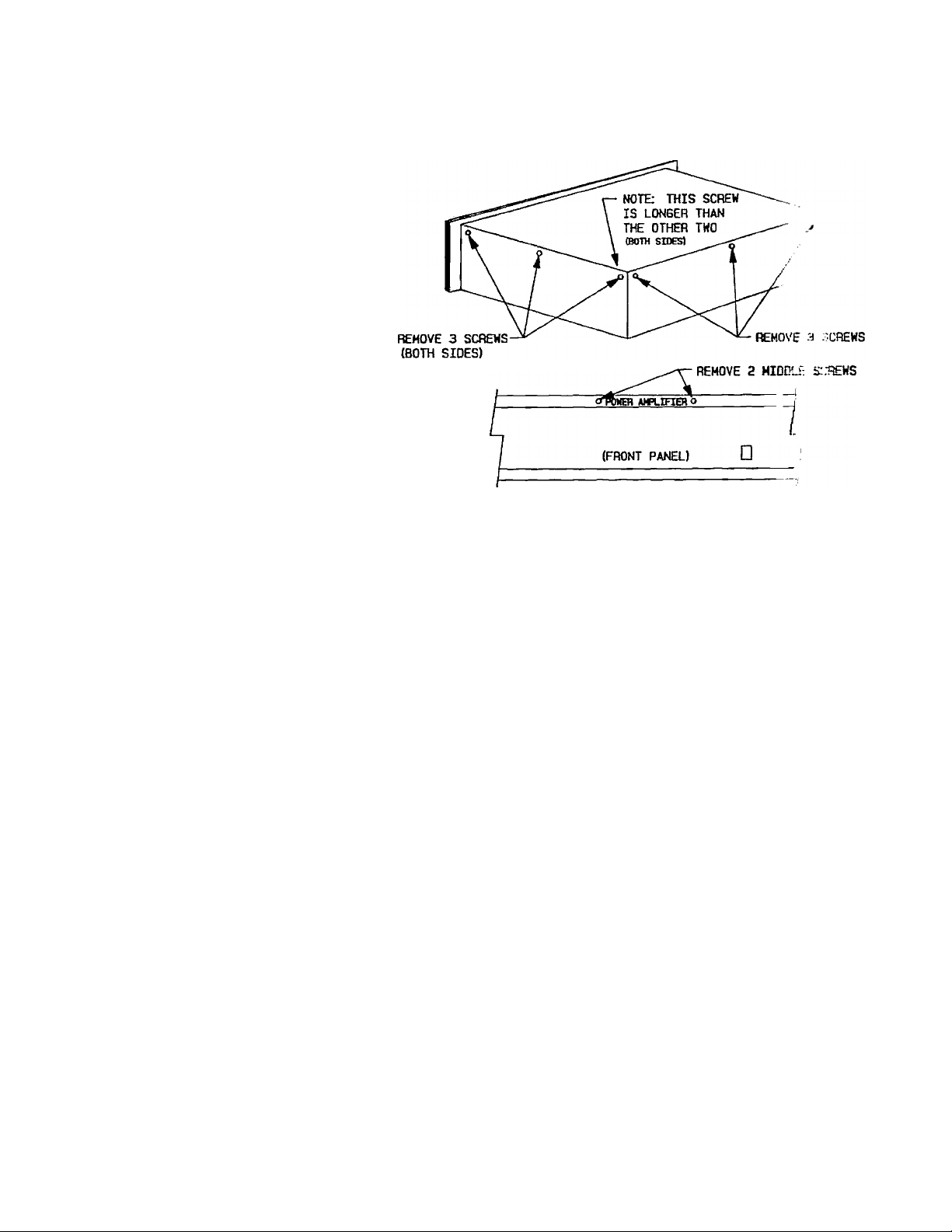
2. Remove and save the ele
ven screws securing the
top cover. There are three
screws on each side and
three along the top-rear
edge of the chassis. In
addition, you must remove
the two iimermost screws
inset into the top bumper
strip. Refer to Figure 1 for
the exact screw locations.
Figure 1 Top Cover Removal
3. Locate terminal blocks
TBl and TB2 on the side
of the chassis near the
rear input PC board. Re
connect the leads as
shown in Figure 2b.
4. Install the top cover with
the eleven screws previ
ously removed. Two scr
ews г!ге longer than the
others removed from the
sides and rear. These
longer screws install into
the reeirmost position on
each side of the chassis.
5. Install an 5A fuse, Littel-
fuse Type ЗАВ 5A/250V
slo-blo 326-series ceramic
body or equiv.
2 INSTALLATION
2.1 Rack Mounting
The amplifier ’nay be in
stalled in a standard 19 inch
equipment rack. It :■ .niires 5V4
inches of vertical rack fipace and
secures to the rack -iibinet with
the four rack mount screws emd
cup washers provided ui the hard
ware kit.
2.2 Ventilation
The amplifier must be ad
equately ventilateo ' e, avoid ex
cessive temperatur- r- ^. It should
not be used in area.' where the
ambient temperature '.xceeds 60
°C (140 °F). To determine the am
bient air tempera: i. : r, operate the
system in the rack until the temp
erature stabilizes. Measure the
ambient air with a bull.-type ther
mometer held at tlie Dottom of the
uppermost amplifier Do not let
the thermometer torich the metal
chassis because the chassis will be
hotter than the ambjent air. If the
ALTEC LANSING* CORPORATION • a Mark IV Company
Page 4

Operating and Service Instructions for the Altec Lansing 9444B Power Amplifier
typical output connections.
3.4 Output Cable Select I<
Speaker wire size pla>^: ft'.
important part in quality so.,
systems. Small wire gauges c.
waste power and reduce the dam
ping factor at the sp>eaker ter t-
Lnals. Ibis can add coloration a;
muddiness to the sound. To Ы-'г.
offset this problem. Table I r
been assembled to enable yoi;
calculate the power losses in e
speaker cable.
3.4.1 Calculating Powe
Losses with 8 ob^
Loads
To calculate the to
power loss in the speaker cable,
multiply the power loss per Го
(or meter) of the 2-wire cal
selected from Teible I Ьз' и»
length of the cable in feet
meters). For example, suppos. a.
installer uses 160 feet of 10 GA
wire cable with an 8 fl speai •
^stem. Ibe total power loss
Figure 2 Primary Wiring Configuration for 120 V ac and 220/240 V ac
air temperature exceeds 60 °C
(140 ®F), the equipment should be
spaced at least 1.75 inches apart
or a blower installed to provide
sufficient air movement within
the cabinet.
WARNING: Do not operate the
amplifier within a completely
closed unventilated housing.
S SIGNAL CONNECT
IONS
3.1 Input Connections
Balanced input connect
ions may be made to either the
barrier strip or the female XLR
connectors. For single-ended in
puts, strap the low (—) input to
ground (pin 3 on XLR). Other
wise, the electronically-balanced
input stage will see 6 dB less in
put signal level than with a bzJanced input. Refer to Figure 3 for
typical input connections.
3.2 Line Output Connect
ions
The XLR and barrier strip
connectors are wired in parallel.
Pin 2 of the XLR is the (-f-) input
on the barrier strip, and pin 3 is
the (—) input. Since the input im
pedance of the electronicallybalanced input stage is high (15
kohms), there is minimal loading
on the signed source. When the
input connections are made to one
connector, the other may be used
as an auxiliary line output to feed
other high input impedance equip
ment. Refer to Figure 3 for poss
ible applications.
3.3 Output Connections
Output connections are
made to the four terminal barrier
strip connector located on the rear
of the unit. Refer to Figure 4 for
the cable is;
Total Power Loss in cable
= 0.0509 watts/foot X 160 feet
= 8.1 watts
Does this mean that whenever
amplifier produces 200 wattr
output power, 191.9 watts (20^
watts minus 8.1 watts) will Ы
delivered to the 8 ohm load? NOI
Tire actual load impedance is
ohms plus the resistance of t
cable (0.00204 ohms/foot thu'
160 feet) for a total load imp
dance of 8.3264 ohms. At the 8 ,
rated output power, the outpu
voltage is 40 V rms. Therefor
the amplifier produces 192.2 watv; .
with this load instead of 2i''.
watts. This was calculated
.squaring the voltage and dividinr
by the load impedance (40^ divl
ed by 8.3264 ohms). As a resui: ,
the actual power delivered to
load is
minus 8.1 watts).
184.1 watts (192.2 watr
ALTEC LANSING* CORPORATION • a Mark IV Company
Page 5

Operating and Service Instructions for the Altec Lansing 9444B Power Amplifier
Losses with ohm
Loads
SOURCE
Figure 3 Typical Input Connections
AMPLIFIER’S OUTPUTS
AMPLIFIER’S INPUTS
LOUDSPEAKER LOADS
AUX OUTPUTS
when using a 4 ohm г.р‘ =акег sys
tem, multiply the loss 3 ohms
by 8. In the above example, the 10
GA wire would comiuaie 24.3
watts of power while !■ 18 GA
wire would waste 15-‘ watts -
more than half of the amplifier's 4
ohm power rating.
3.5 Damping Fact-.; r
factor rating of air amplifier, the
greater the ability of Üi- amplifier
to control unwanted sp- sker cone
movements. When a signal drives
a woofer, current flow;¡ ’.hrough
the voice coil creates ■ uagnetic
field. This field inters. ^ with the
permanent magnetic field in the
gap and forces the combination
cone and voice coil aiisembly to
move outward. When i he signal is
removed, the assembly moves in
ward but its momeid.ii causes it
to overshoot its resting point. This
overshoot will damfx n iLself out
eventually but the unwanted mo
vements can add consirierabie dis
tortion products to 111-' .'iound
To calculate ti: losses
The higher thi diunping
Figure 4 Typical Output Connections
Had 18 GA wire been used in the
above excunple, the loss in the
cable would have been 51.9 watts.
This example illustrates the im
portance of using the proper wire
size.
3.4.2 Calculating Power
In the process of movitig inward
through the magnetic field, the
voice coil assembly generates a
current of opposite polarity to the
original signal. This current
induces a voltage or “1- ick EMF”
which travels through ihe speaker
wore to the ampiiiler's output.
The lower the amplifier’s output
impedance, the faster the over
shoot of the voice coil vill dampen
out. The output impeilance of an
amplifier can be calculated by
dividing the rated output impe
dance, typically 8 ohms, by the
damping factor. The U-144B has a
damping factor rating of 200
which correspond^ .■ an output
imp>edance of 0.04 ohms.
S.tS.l Calculating the
Maximun i<‘ngth of
Cable for ü Specified
ALTEC LANSING^ CORPORATION • a Mark IV Company
Page 6

Operating and Service Instructions for the Altec Lansing 9444B Power Amplifier
Damping Factor Spec
ification at the Load
The damping factor rating
is ^rpically never realized at the
load because of the resistance of
the cable (and other factors such
as the contact resistance of an
output relay or the resistance of
an output fuse). The damping fac
tor at the load should be 30 for
general paging ^sterns and 50 for
high fidelity music ^sterns. Econ
omics usually dictate, however,
that these numbers are cut-in
half. The resulting damping factor
at the load should be based on
experience and customer satis
faction. Once a minimum damping
factor is determined for a partic
ular type of installation, the fo
llowing equation can calculate the
maximum length of 2-wire cable
which can be used to achieve the
minimum damping factor specified
at the load;
Max. Length of 2-wire cable in
feet
ZL — Zo
= DF
DCR/ft
where
ZL is the load impedance
to connect to the amp
lifier;
Zo is the amplifier’s
output impedance (0.04
ohms for the 9444B);
DF is the minimum
permissible damping
factor at the load; and
DCR/ft is the DC resis
tance of the 2-wire cable
per foot from Table I.
The same equation can be used to
calculate the maximum cable leng
th in meters by substituting the
DCR per meter value from Table
I.
Let’s use the equation. Suppose
ZL equEils 8 ohms, Zo = 0.04
ohms, and the minimum damping
Table I 9444B Power Losses in 2-wire Speaker Cable
AWQ
(GA)
6
8
10 0.00204
12 0.00.124
14 0.00510 0.1286
16
18 0.01302
20
22 0.03292 0.8163
DCR/ft
(n/ft)
0.00081
0.00121
0.00819
0.02070 0.5148
factor at the load is 25. In add
ition, 18 GA cable is preferred.
Then, the maximum length of 18
GA cable which can be used to
achieve a damping factor of 25 at
the load is:
Power Cable Croaa- Power
Loss/ft
(walWft)
0.0201
0.0302
0.0509
0.0809
0.2043 1.31
0.3244 0.82
SccI ional
area (mm*)
13..30 0.00264 0.0661
8.36 0.00421 0.1051
5.26
3.31
2.08 0.01691 0.4210
0..52 0.06764 1.6627
0.33
DCR/nietcr
(n/m)
0.006CO
0.01003 0.2650
0.02685 0.6667
0.04289
0.10658 2.5950
V is the stepped-up ii.
age of the system;
Pout is the rated output
power of the amplifier:
Zo is the output impetl
ance of the amplifier (O.Gohms for the 9444B);
8 — (0.04)
^5
___________________
0.01302 n/ft
= 21.5 feet
ZL is the load impedaiic.;
DCR/ft is the DC resis
tance of the 2-wire cabL
per foot from Table I; anti
DF is the minimum pf
Sometimes it may be necessary to
locate the speaker 100 feet or
missible damping facte r
the load.
more away from the amplifier. In
this situation, a much larger
gauge cable is required. However,
this may not be practiced or eco
nomical. 'The size of the 2-wire
cable can be greatly reduced by
stepping up the output voltage of
the amplifier to 70, 100, 140, or
210 volt, using an output trans
former, then stepping down the
voltage at the load. Such a system
Suppose a 210 volt ^stem werv
used at a 600 watt power level '
drive an 8 ohm load with a min:
mum damping factor of 25. Using
the same 18 GA cable as before,
the maximum length can now t)6
198 feet. Power companies
this teclinique to transfer large
amounts of power over great dis
tances.
is shown in Figure 5.
3.6 Speaker Protection.
The maximum length of 2-wire ca
ble in this situation can be ap
proximated from the following
equation:
irable to use in-line fuses (fuses i:.
series with the output) to protect
Fuse Selection
Sometimes it may be des
loudspeciker ^sterns (or the amp
Max. Length of 2-wire cable in
feet
lifier). It is difficult, however,
determine the proper fuse valttv
with the correct time lag anrl
1 Zo
(Pout)(DCR/ft) DF ZL
overload characteristics to match
the limitations of a speaker sy-s-
tem. The values shown in Table II
where
should serve only as a guide. To
Loss/raotc
(watts/m
0.1669
1.0609
ALTEC LANSING* CORPORATION • a Mark IV Company
Page 7

Operating and Service Instructions for the Altec Lansing 9444B Power Amplifier
Lansing recommends using a ca^
acitor between the aimplifier and
the compression driver to supp
ress low frequencies an; ossible
DC. Refer to the exam : e in Fig
ure 4.
In choosing a value, one must be
careful not to interfere -vith the
crossover frequency. A-: -general
rule, select a сарае:' whose
break frequency, with respect to the
load, is 3 dB down, at approximate
ly Vi of the high pass comer fre
quency.
Mylar capacitors witli at least a
100 volt ac rating are rec-.nmend-
ed. Table III shows ‘ e recom
mended capacitor vnhies for use
with 8 and 16 ohm dri > crs at pop
ular crossover frequencies.
Figure 5 High-voltage Distribution System
use, determine the power rating
where
and load value. Then, select a
standard value fuse of the next
smaller value to the one listed in
the table.
Use 32 volt fuses if possible; they
Table П Calculated Output Fuse
Values
typically have the lowest internal
resistance which will help mini
mize deterioration of the damping
Power 4 n
(wutta)
100
150
200
300
400
600 9.07
Load
3-70 2.62 1.85
4..54 3.21
5.24 3.70 2.62
6.42
7.41 5.24
8П
Load
4.54
6.42 4.54
16 n
Lead
2.27
3.21
3.70
factor at the load. Refer to the
example in Figure 4.
3.7 Compression Driver
for mid to high frequency sound
reproduction, are much more sus
ceptible to damage from low fre
The values are calculated for fast-
blow fuses which carry 135% of
their current rating for an hour
but will blow within 1 second at
200%. Other fuse values may be
calculated for different power
levels from the following equation:
quencies than large cone loud
speakers. Even though an elect
ronic crossover may be employed,
problems may arise in the cables
between the crossover and the
power amplifier, or from raisad-
justment of the crossover. Either
of these situations could apply low
Fuse value =
(Pout X ZL)^ amps
ZL X 1.35
frequency signals or hum to the
driver and cau.se damage. To pre
vent a potential mishap, Altec
Pout is the output power
rating of the amplifier;
and
ZL is the load impedance.
Protection Capacitors
Compression drivers, used
Table Ш Compre; lí-- ; t fLl
Driver
Protection Capacitors
Crossover 8П 16
Frequency Driver Driver
500 Hz 80 ¿I- 40 (iF
800 Hz 50 nl1000 Hz 40 цГ
1250 Hz 33 Цр îGnF
2000 Hz 20 jiF 10 liF
3150 Hz
6300 Hz 6 jiF 3 (iF
12 цГ
n
25 irF
20 p.F
6 piF
4 OCTAL ACCESSORY
SOCKETS
Two octal sockets permit a
variety of plug-in acc.er -jori^ to be
used with the amplifier Normally,
one “U” jumper is inserted bet
ween octal socket 8 and 1,
and another betwei:: i ins 7 and 6.
These jumpers must remain in
place for the amplii-rr to operate
when not using ar.‘: accessory
modules. To use with in accessory
module, remove iau save) the
jumpers and insbi]] .he module
making sure the kev >n its center
post aligns with til* ;Toov6 in the
female socket. For operation, refer
to the instructions rovided with
ALTEC LANSING* CORPORATION « a Mark IV Company
Page 8

Operating and Service Instructions for the Altec Lansing 9444B Power Amplifier
the module. Schematically, the
module will be inserted between
the input connector and the bal
anced input stage.
Electronic modules are powered
from a bipolar 15 volt supply in
the amplifier, "nie supply is cap
able of supplying up to 25 ma DC
of current. Currents in excess of
25 ma DC may prevent the ampli
fier from disengaging from its
built-in protection meclianisms.
PROTECTION
TEMS
5.1
ently protects its load from
startup/shutdown transients, DC,
and large subsonic signals.
circuit was designed specifically
for the amplifier. It features a
variable current limit which is a
function of the output signal volt
age. As a result, tlie amplifier can
deliver the rated currents into
rated loads but substantially lim
its the current into low impedance
or shorted loads (shorted output
terminals). Once the short is re
moved, however, the amplifier will
resume normal operation.
A dual speed fan is also incorp
orated to provide efficient cooling
under the most demanding condi
tions. When the heatsink temper
ature at the fin tips reaches ap
proximately 88 “C (190 ®F), the
fan automatically switches to high
speed operation. As the temper
ature cools to approximately 78 “C
(172 °F), low speed operation is
once again resumed.
The heatsink is also thermally
equalised to prevent the output
devices nearest the fan fi-om op
erating at a cooler temperature
Load Protection Cir
cuitry
Each channel independ
5.2 Amplifier Protection Circuitry A unique current-limiting
SYS-
than the devices at the opposite
end. This minimizes the thermal
gradient across the heatsink and
forces the devices to operate at
more nearly the same tempera
ture. Tliis equalizes the lifetimes
and reliability characteristics of
the output devices so that no one
device becomes the weak link in
the chain.
Should the heatsink temperature
of a channel remain excessively
high, the affected channel will
shut down automatically. W^en
the output devices cool to a safe
operating temperature, the chan
nel will automatically resume
normal operation.
5.3 Protect Indicator Tlie “PROTECT” LED
does not turn-on abruptly as
others may do; its intensity is
allowed to vary. As a result, its
degree of brightness serves as a
relative indicator of tire severity of
the current oprerating conditions
e.g., the brighter the LED, the
greater the stress on the chan-
nel(s). This provides a visual not
ification well in advance of any
impending shutdown.
Although the channel may stiU
opwrate with the LED apparently
at full brightness, a total shut
down will occur within a few sec
onds unless the operating condit
ions improve. If a shutdown does
occur, the channel will resume
normal ojjeration as soon as its
devices have cooled to an accept
able temperature.
6
6.1
ation, the channels may be oper
ated independently. After install
ation and hookup, verify that the
mode switch, located on the rear
penel, is in the “DUAL” position
and rotate the level controls fully
OPERATION
Dual Mode of Op>er-
ation
In the dual mode of oper
counterclockwise (full attenr
ion). Input a 0 dBu (0.775 V ;
nominal signal level and ^
pewer. Slowly increase the
controls until the desired oupewer is obtained. If ei'
“CLIP” LED illuminates, re-J
the output with the cheumel
control or reduce the input si;,
level at its source.
WARNING: Never attempt to c-
nect the outputs of the two cka
nets in parallel.
6.2 Bridge Mode of Opation
After installation
hookup, verify that the m<
switch, located on the rear 1x1:1?
is in the “BRIDGE” px>sition. R
ate both levels controls ft. ._
counterclockwise (full attenuu.
ion). Input a 0 dBu (0.775 V nnominal signal level into chanu
1 only and apply pjower. Slowly
crease the level control of chanr
1 until the desired output piowoi
is obtained. If either “CLIP” LL
illuminates, reduce the output le
el with the level control or redu
the input signal level at its sou:
CAUTION: Be sure that no inpi
connections are made to channel
and that its level control is fw
counterclockwise (OFF).
WARNING: The bridged outp:
mode provides a true balanced-it
ground output. Do not use any fc-
equipment to test or evaluate thi
amplifier which does not ha‘
floating grounds.
In Case of Problems
Please check the followii.
items:
Verify that the ampliCe:
is properly connected :
an ac pxjwer source an>
that the source is active.
Verify that the input con
nections are proper!
ALTEC LANSING* CORPORATION • a Mark IV Company
Page 9

Operating and Service Instructions for the Altec Lansing 9444B Power Amplifier
made. Refer to Figure 3.
3. Verify that the output
connections are prof>erly
made. Refer to Figure 4.
4. Check the input and out
put cables for proper
wiring and continuity.
5. Check the signal source
and the load.
Insure that the two jump
ers for each octel socket
are properly installed (if
not using optional plug-in
modules).
Insure that any accessory
modules installed do not
draw more than 25 ma
DC of current.
8.
NOTICE: Repairs performed by
other than authorized warranty
stations (Dealers) or qualified
persomiel shall void the warranty
period of this unit. To avoid loss
of warranty, see your nearest Altec
Lansing authorized dealer, or call
Altec Lansing Customer Service
directly at (405) 324-5311, FAX
(405) 324-8981, or write:
Altec Lansing Customer
Service/Repair
10500 W. Reno
Oklahoma City, OK 73128
U.SA.
Check that the mode
switch is in the desired
position.
AJLTEC LANSING^ CORPORATION • a Mark IV Company
Page 10

Operating and Service Instructions for tfie Altec Lansing 9444B Power Amplifier
8 SPECIFICATIONS
Conditions:
1. 0 dBu = 0.775 volts rms.
2. Dual mode ratings are for each channel.
3. Both channels operating at rated output power
unless noted.
4. 120 volt ac line input voltage maintained for all
tests unless noted.
Continuous Rated Output Power:
(20 Hz - 20 kHz at less than 0.1% THD)
Dual mode, 4 D: 300 watts/ch
Bridge mode, 8 SI: 600 watts
Dual mode, 8 SI: 200 watts/ch
Bridge mode, 16 D; 400 watts
Continuous Rated Output Power to Subwoofer:
(20 Hz - 1 kHz at less than 0.1% THD)
Dual mode, 4 O: 375 watts/ch
Bridge mode, 8 D: 750 watts
Dual mode, 8 Si: 225 watts/ch
Bridge mode, 16 fi: 450 watts
Maximum Midband Output Power:
(Ref. 1 kHz, 1% THD, @120 volts ac line voltage)
Dual mode, 4 SI: >400 watts/ch
Bridge mode, 8 SI: >800 watts
Dual mode, 8 SI: >250 watts/ch
Bridge mode, 16 SI: >500 watts
(Ref. 1 kHz, 1% THD, @108 volts ac (10% sag))
Dual mode, 4 SI: >325 watts/ch
Bridge mode, 8 il: >650 watts
Dual mode, 8 il: >200 watts/ch
Bridge mode, 16 fi: >400 watts
(Ref. 1 kHz, 1% THD, @100 volts ac (17% sag))
Dual mode, 4 il: >230 watts/ch
Bridge mode, 8 il: >460 watts
Dued mode, 8 il: > 175 watts/ch
Bridge mode, 16 il: >350 watts
Headroom (Before clip): S1 dB
(Ref. 1 kHz, 1% THD, any mode)
Frequency Response: 10 Hz - 90 kHz
(Ref. 1 kHz, 1 watt output, +0/—3 dB)
Power Bandwidth: 20 Hz - 20 kHz
(Ref. 1 kHz, +0/—1 dBr where 0 dBr = rated output
power in any mode)
Voltage Gain:
(Ref. 1 kHz)
Dued mode, 4 il or 8 il;
33 dB
Bridge mode, 8 or 16 Q: 39 dB
Input Sensitivity for Rated Output Power:
(Ref. 1 kHz, ±0.15 dB)
Dual mode, 4 il:
Bridge mode, 8 il:
Dual mode, 8 il:
Bridge mode, 16 SI:
Maximum Input Level:
(Ref. 1 kHz)
Input Impedance;
(Ref. 1 kHz)
Balanced:
Unbalanced:
Polarity:
Phase Response:
(Any mode)
20 Hz:
20 kHz:
THD:
(Any mode, 30 kHz measurement bandwidth)
IMD (SMPTE 4:1); <0.05% (Typ. <0.01%)
(Any mode)
TIM (DIM 100): <0.05%
(Any mode)
Rise Time: <6 psec
(Any mode, 10% to 90%)
Slew Rate:
Dual mode, 4 or 8 il: >30 V/psec
Bridge mode, 8 or 16 il; >60 V/psec
Damping Factor;
(Dual mode, 8 D)
20 Hz - 1 kHz:
20 kHz:
Crosstalk: <75 dBr
(Ref. 1 kHz, 0 dBr = rated output power into 8
ohms, single channel operating)
Noise; > 100 dB
(Below rated output power, A-weighting filter, 8 f ‘
+0.1 dBu (0.78 V rms
+0.1 dBu (0.78 V nus'
+ 1.2 dBu (0.89 V rm;
+1.2 dBu (0.89 V rm
+20 dBu (7.75 V rm.s
15 kil
15 kD
Positive-going signapplied to pin 2 of X' :
or (+) of barrier strip
produces positive-gv ;
signal at (+) outp
terminal.
<+25°
>—15°
<0.1% (lyp. <0.01%.
>200
>75
ALTEC LANSING^ CORPORATION • o Mark IV Company
Page 11

Operating and Service Instructions for the Altec Lansing 9444B Power Amplifier
dual mode, 50/60 Hz ac line frequency)
Amplifier Protection:
Load Protection;
Cooling:
Heatsink:
Fan:
Output Topology:
Output Type:
Dual mode:
Bridge mode:
Output Devices:
Total number:
Pdmax rating:
Vceo:
Ic:
Tjmax:
Controls and Switches:
Rear:
Front:
Front Panel Indicators: Power LED, Clip LED (x
Connections;
Input:
Shorted output term
inals, Over-temperature,
RF interference
Startup/shutdown trans
ients, DC faults. Sub
sonic signals
Thermally equalized 3/16
in aluminum black ano
dized heatsink
Thermostatically con
trolled dual speed fan.
Approximately 50 CFM
at low speed and 100
CFM at high speed. Ball
bearing fan has mini
mum life rating of
50,000 hours at 25 °C
ambient temperature
True complementary
symmetry with grounded
collectors (no mica
insulators means better
heat transfer)
Unbalanced, each chan
nel
Balanced
16 devices
250 watts
250 volts DC
16 amps DC
200 °C
Mode switch, Two input
level controls
Power switch
2),Protect LED (x 2)
6 terminal barrier strip,
Female XLR (x 2),
Octal accessory socket (x
2), powered with ±15
volts DC at 25 :'-¡i.
Output:
Power:
Fuse ТУре;
Power Requirements;
Operating ac Voltage
Range:
Power Consumption/
Heat Produced:
(Both channels operating in dual mode '.viih 1 kHz
sinewave input signal at stated output power into 4
Cl loads)
idle:
l/8th max
midband power:
l/3rd max
midband power:
Rated output power:
Max midband power:
Operating Temperature
Range:
Dimensions (Rear of rack ears to max depth):
Barrier strip
6 ft (1.83 m). :^-wire, 16
GA power cord with
NEMA 5-15 ;:!:jg/rEC
Littelfuse TVps ЗАВ 10
A/250 V Sl^Blo® 326-
series ceramU ..irtridge
body, or equivakmt (for
120 V ac use
120 V ac, 50/6Й Hz, 1000
watts (configurable to
220/240 Vac. ; 00 Vac,
5 0/60 Hr model
availeihle.
Operates line
voltages as ! iv as 90
volts (at redv:oitl output
power) assu;-:!T!r: a 120 V
ac nominal i; '
72 watt&'0,24ò кВТи/h
720 watta'2.100 ,kBTU/h
1,068 w.4t.i.s/2.702
kBTU/h
1,464 w«*t,s/2.938
kBTU/h
1,680 w-as/2.873
kBTU/h
Up to 60 C (140 “F)
ambient
5.25 in Hx 19 inWxl3
in D
(13.3 cm b -^8.3 cm W
X 33 cm DI
ALTEC LANSING* CORPORATION • a Mark IV Company
Page 12

Operating and Service Instrifctions for the Altec Lansing 9444B Power Amplifier
Shipping Weight:
Net Weight:
Colon
Enclosure:
Standai*d Accessories:
Optional Accessories:
42 lbs C19.1 kg)
34 lbs (13.5 kg)
Black
Rack mount chassis, 16
GA steel, 3/18 in 5052
aluminum alloy front
panel
4 - “U” jumper plugs for
octal sockets (2 per
socket, installed)
1 - Operating Instruct
ions and Service Manned
1-5 A/250 V fuse (for
220/240 V ac use)
14712A Power Limiter
15515A Input Bridging
Transformer with Pad
15524A 300 watt 70 volt
Transformer
15525A 600 vpatt 70 volt
Transformer
15367A 300 watt Auto
former
15581A 24 dB/oct
Link wit2-Riley C rossover
15594A-XXX 18 dB/oct
Low Pass Filters
15595A-^ 18 dB/oct
High Pass Filters
The “-xxx” represents various corner frequencies
available for the corresponding filter.
ALTEC LANSING CORPORATION continually
strives to improve products and performance.
Therefore, the specifications are subject to change
without notice.
Slo-Blo® is a registered trademark of Littelfuse,
Inc.
10
ALTEC LANSING^ CORPORATION • a Mark IV Company
 Loading...