

Page 1
Page 2

Preface
The PowerFlex Reference Manual provides the information necessary to operate your new
PowerFlex computer manufactured by Advanced Logic Research, Inc. (ALR). This manual
assumes you have some experience using IBM-type personal computers and are familiar with
DOS operating systems. You should know how to use a standard keyboard and understand
special keys (for example, CTRL). You can obtain background in these areas by referring to your
DOS system documentation. Additional information is available in a variety of instruction
manuals for IBM PC and AT systems. You can purchase these manuals at your local bookstore.
The PowerFlex Reference Manual is organized as follows:
Chapter 1, General Information — describes the major components of the PowerFlex system.
Chapter 2, Getting Started — explains how to set up the PowerFlex system. It lists the
PowerFlex components, how to properly unpack, hook up the monitor and keyboard, and
initialize the system with a DOS diskette. The SETUP program and memory features are also
described.
Chapter 3, using the Utilities Diskette — discusses the hard disk formatting, EMS, and other
utility programs available with the PowerFlex.
Chapter 4, Basic System Configurations — describes the configuration of the 286
motherboard. Topics covered include memory installation and configuration, motherboard
pinouts, and serial and parallel port configurations.
Chapter 5, Options — explains how to configure and install optional equipment available for
the PowerFlex. Optional equipment includes the PowerFlex modules, math coprocessors,
graphics adapters, 3½ and 5¼-inch floppy disk drives, and tape backup systems.
Appendix A, Error Messages — lists nonfatal and fatal system board beep codes. Descriptions
of various errors and solutions to nonfatal errors are also provided.
Appendix B, Hard Disk Drive Characteristics — lists the 49 drive types supported by the
PowerFlex.
PowerFLEX Users Manual i
Page 3

Conventions Used In This Manual
The following conventions are used in this manual:
<Enter> <Enter> means you press the Enter (¿) key. After you type a keyboard
entry, you press the Enter key to execute the entry.
Keyboard entries Keyboard entries are BOLD. For example:
A>PROCEED WITH FORMAT (Y/N)?
A>Y <Enter>
After the system prompt (A>), the computer asks if you want to proceed.
Your keyboard entry in this example is Y (yes).
Keyboard sequence When a key sequence is hyphenated, press the keys in the order shown.
All keys must remain pressed until the sequence is complete. For example:
C > CTRL-C
means hold down the CTRL key and press the C key (CTRL-C generally
ends a program).
In the following example:
C> CTRL-ALT-DEL
means you hold down the CTRL key first, then hold down the ALT key
and press the DEL key. The CTRL-ALT-DEL sequence reboots the
system.
Typing commands You can enter commands in either upper- or lowercase letters. For
example, entering:
A>dir <enter> is the same as entering:
A>DIR <Enter>
Variables Words within < > angle brackets are variables and can have many names.
Options Words or items within square brackets [ ] are options. Enter only one of
the options from the list provided.
PowerFLEX Users Manual ii
Page 4

Chapter 1, General Information
In the rapidly changing world of computer technology, every computer owner wonders if their
system could one day become obsolete. ALR has conquered the fear of obsolescence with the
introduction of the PowerFlex, a 286-based system enhanced with ALR’s unique 108-pin
386/1486 Feature Connector. This unique feature currently allows you to upgrade the standard
12.5-MHz 286 PowerFlex system to a 16-MHz 386SX or 25-MHz 1486 system by plugging in
either a PowerFlex 16-MHz 386SX or 25-MHz i486 Module. That’s all there is to it. There are
no switches to change on the 286 motherboard. When you plug a PowerFlex Module in, it simply
takes over and you instantaneously attain the higher technological level that you were seeking.
Furthermore, ALR has no intention of limiting the PowerFlex to the 386SX and i486 modules.
Future PowerFlex modules with even higher levels of technology are already being developed.
When you’re ready to move up from 286 technology, simply contact your authorized ALR dealer
to learn what PowerFlex modules are being offered, and to decide which upgrade module would
best suit your needs.
PowerFlex system
The PowerFlex is a flexible IBM AT-compatible computer. The motherboard provides
embedded I/O ports, floppy and hard disk controllers leaving all six IBM PC/AT expansion slots
available for individual requirements. The PowerFlex also features a unique hardware and
software Expanded Memory Specification (EMS) device driver that allows the user to run
extended features of many popular software applications such as Lotus 1-2-3, Ventura Desktop
Publishing, and Microsoft Windows. Add to this ALR’s unique 386/i486 Feature Connector, and
you have a system that is almost boundless in its expansion capabilities, making the PowerFlex
the ideal entry-level computer.
The standard PowerFlex is a 12.5-MHz 286 CPU system with a 3½-inch 1.44-MB floppy disk
drive using the motherboard’s embedded floppy controller. The embedded 40-MB < 40ms
AT-style hard disk drive provides full-track buffering and 1:1 page interleave.
The chassis is ALR’s specially designed small footprint AT-style desktop with a total dimension
of 6" H x 15" W x 17" D which can accommodate two half-height 5¼-inch and two 3½-inch
devices.
PowerFLEX Users Manual 1-1
Page 5
General Information Components and performance features
Components and performance features
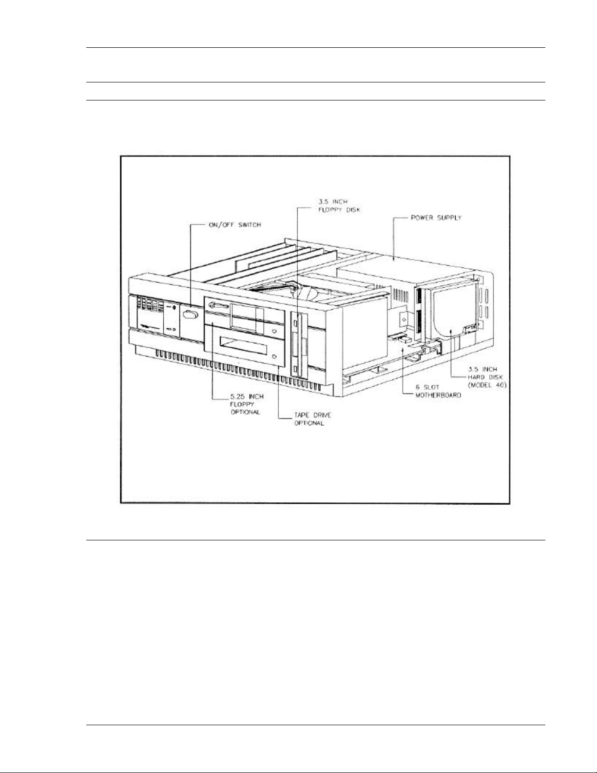
Figure 1-1 shows the major components inside the PowerFlex. The following subsections
describe these major components.
Memory
The PowerFlex is based on a 12.5-MHz 286 motherboard. The standard PowerFlex contains
1-MB of paged mode memory that occupies Banks 1 and 2. Banks 3 and 4 each contain two
rows of Single Inline Memory Module (SIMM) connectors for mounting additional 256K x 9 or
1MB x 9 SIMMs. The maximum onboard memory is 5-MB. System memory may be expanded
to 16-MB with the use of third party 16-bit memory expansion cards. See Chapter 4 of this
manual for complete memory configuration and installation details.
PowerFLEX Users Manual 1-2
Page 6

General Information Components and performance features
Drives and controllers
The PowerFlex chassis accommodates two 3½-inch and two 5¼-inch devices. The floppy disk
drive included with the PowerFlex is a 1.44-MB 3½-inch floppy drive. The drive is springloaded
and ejects diskettes about an inch. The floppy controller, integrated on the 286 motherboard,
supports up to two 3½-inch drives with 720-KB or 1.44-MB capacities or, up to two 5¼-inch
drives with 360-KB or 1.2-MB capacities.
The standard PowerFlex includes a 3½-inch 40-MB (<40ms) embedded hard disk drive. This
drive is a special AT-interface drive that contains controller functions; hence, the name
embedded hard disk drive. In addition, the controller functions can accommodate up to two hard
disk drives allowing for storage expansion.
The PowerFlex chassis can accommodate two other half-height devices. You can use these
storage bays to install optional floppy drives (any combination of 3½ and 5¼-inch drives are
possible), hard disk drives, or tape backup systems. See Chapter 5 for further details.
BIOS EPROM
The Basic Input/Output System (BIOS) from Phoenix Technologies Ltd. controls the
input/output (110) devices in the system. The I/O protocol for peripheral devices such as
terminals, printers, and scanners is completely IBM-compatible.
There are no switches to set on the PowerFlex as all configuration changes are made through the
PowerFlex SETUP program. A special SETUP screen, dedicated solely to select Soft Switch
options, is one of three SETUP screens specially designed for the PowerFlex (see Chapter 2). An
additional feature of the BIOS allows you to activate the SETUP program by pressing
simultaneously the CTRL-ALT-ESC keys at the DOS prompt, or if the system’s setup
configuration is incorrect, the system prompts you to press the F2 key.
Keyboard features
The PowerFlex includes an enhanced IBM AT-compatible keyboard with the added feature of
audible keystrokes. Plus, you can change the operating speed by simply pressing the
CTRL-ALT-MINUS or CTRL-ALT-PLUS sequences (see Chapter 2).
Standard software
The utility programs in the utilities diskette include hard disk formatting programs, drivers for
two versions of Novell’s NetWare, and the Expanded Memory Specification (EMS) device
driver. The diskette provides separate subdirectories containing each set of utility programs.
Each subdirectory includes a README file explaining the functions of the associated utility.
Chapter 3 describes how to use the utilities diskette.
ALR does not provide standard DOS with the PowerFlex. However, the PowerFlex is compatible
PowerFLEX Users Manual 1-3
Page 7

General Information Components and performance features
with MS-DOS 3.3x and IBM PC-DOS version 3.3. ALR provides MS-DOS version 4.01 as an
option. Note: The BASIC and BASICA software from IBM PC-DOS will not run because they
require BASIC support in the BIOS and therefore will run only on IBM systems. We do include
GW-BASIC in our MS-DOS option; this will provide the same function as BASICA
(GW-BASIC is written by Microsoft).
Specifications
Processor (CPU) 16-bit 286 operating at 12.5-MHz
Coprocessor Socket for an Intel 8-MHz 80287 or 12-MHz 80C287A- 12
Clock Calendar IBM AT-compatible clock calendar with on board NICAD
rechargeable battery (10 Year Lifetime)
BIOS Phoenix, 64-KB EPROM with on board setup
Expansion Available for user requirements: one 8-bit and five 16-bit
slots; one dedicated 386/i486 Feature Connector
Memory 286 motherboard contains 1-MB of standard memory and
four rows of SIMM connectors (2 rows per bank) to add an
additional 4-MB
On Board 1-MB memory: 640-KB of real memory and 384-KB of EMS
memory; optional onboard expansion to 5-MB
System 16-MB total system expansion using third party 16-bit
memory expansion cards
Floppy/Hard Disk Subsystem
Floppy Drive One 1.44-MB 3½-inch floppy disk drive
Hard Disk Drive High-performance 1:1 interleave 40-MB <4Oms embedded
AT hard disk drive with accommodations for optional second
1:1 interleave 40-MB <40ms embedded AT hard disk drive
Controllers Embedded AT-interface floppy and hard disk controllers
I/O Ports one serial, parallel and keyboard port
Keyboard 101-key, enhanced
Software utilities diskette
PowerFLEX Users Manual 1-4
Page 8

General Information Specifications
DMA Controllers Dual DMA controller, one for 8-bit transfers and one for
160-bit transfers
Interrupts
Interrupt Function
0 Timer Channel (Time of Day)
1 Keyboard
2 Cascade (Interrupts 8-15)
3 COM2 and Expansion Slots
4 COM1 and Expansion Slots
5 Parallel Port and Expansion Slots
6
Floppy controller
7 Parallel Port and Expansion Slots
8
Calendar
9-12 Expansion Slots
13 80287 Math Coprocessor
14-15 Expansion Slots
Timer 8254-compatible timer with 840ns resolution. Three timer
channels are available:
Channel Fucntion
0 Time of Day
1 Refresh
2 Speaker
Dimensions 6” H x 15” W x 17” D
Weight 35 lbs.
Power Supply 150 watts
AC Input 110 VAC or 220 VAC
DC Output 4.5A @ + 12V ±5%
.3A (max) @ -12V ±10%
18A(max)@ +5V±5%
.3A (max) @ -5V ±10%
Temperature
0 to 40° C
Humidity 0 to 90% non-condensing
Altitude 8,000 feet
PowerFLEX Users Manual 1-5
Page 9

Chapter 2, Getting Started
Charging the system battery
This system is equipped with a Nicad rechargeable battery with a built-in trickle-charge circuit.
A completely charged battery will maintain its charge for two months. Upon delivery this system
battery requires an initial charging period of approximately 12 hours. Prior to complete charging,
the system may power up with an error in the setup configuration. Should this occur, simply
press the F2 key to run the SETUP program. Refer to the section entitled, “SETUP program,”
later in this chapter for further information on the SETUP program.
To charge the Nicad battery, simply plug your PowerFlex into a 3-prong, 115-volt AC surge
control outlet station and turn the system ON. Leave the system running for at least 12 hours to
fully charge the battery.
After charging, the Nicad battery should provide approximately a two-month backup charge
without a recharge (recharging is done by running the system). The total lifetime of the battery is
approximately 10 years.
Hooking up the monitor and keyboard
The monitor and keyboard are completely assembled at the factory; however, you must connect
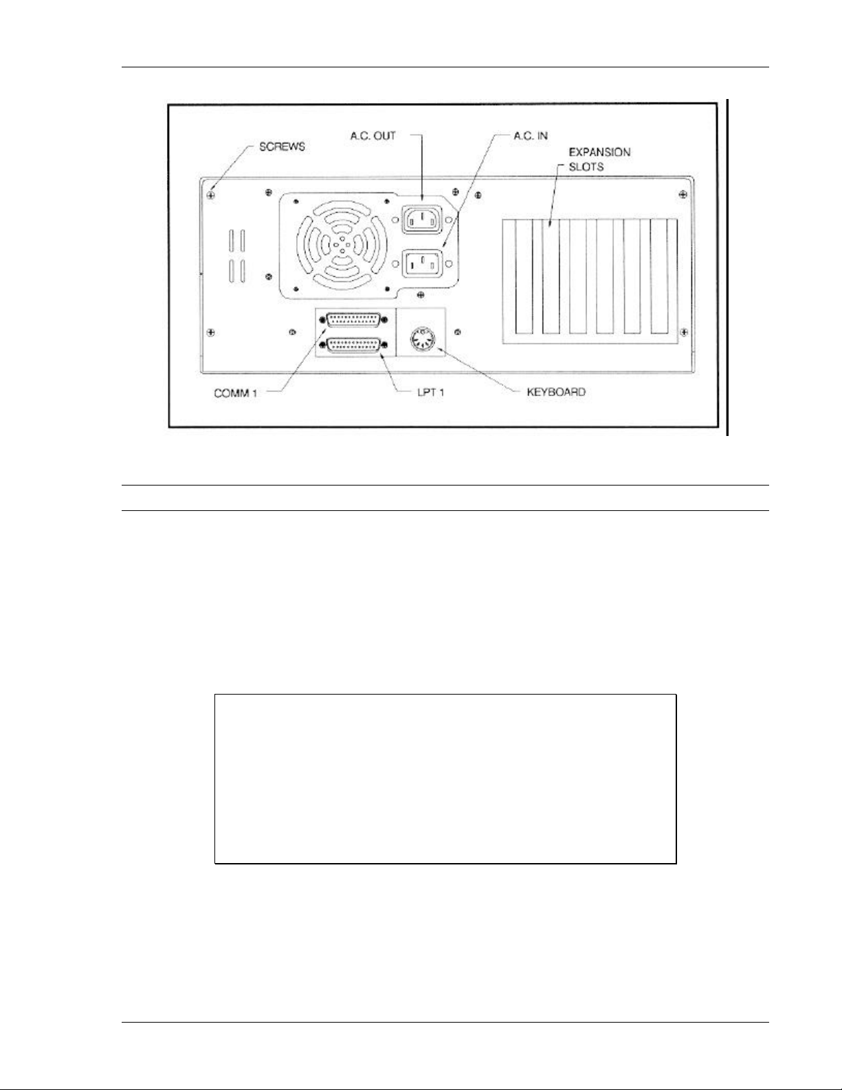
cables between the system, the monitor, and the keyboard. Figure 2-1 shows the rear of the
PowerFlex chassis. This figure shows input/output (I/O) connectors for the keyboard, monitor
(A.C. OUT), and optional equipment (COM1, LPT1 and Expansion Slots).
Connect your monitor and keyboard securely into the proper connectors. Most monochrome
monitors have a separate ON/OFF switch and a power connector that plugs into the rear of the
chassis. Refer to the appropriate manual that came with your monitor for further details.
PowerFLEX Users Manual 2-1
Page 10
Getting Started Hooking up the monitor and keyboard
Figure 2-1: Rear of the PowerFlex
Power-up operation
Turn the power ON. The ON/OFF switch is at the front of the chassis as shown in Figure 1-2.
Turn the monitor power ON. The power LED lights if power is on.
On power-up, the PowerFlex checks its system memory. This occurs whether or not the monitor
is also on. The system memory check (called the Power-On Self-Test or POST) takes from 3 to
15 seconds to complete, depending on system memory capacity. It ends with a single beep and a
display of the time and date. The monitor displays the power-on message, as shown in
Figure 2-2.
Phoenix ROM BIOS PLUS Version x.xx
Copyright (C) 1985-1986 Phoenix Technologies Ltd.
All Rights Reserved
Advanced Logic Research Inc. PowerFlex 286/386SX
<640K> Base Memory, <384K> Extended Memory
Non-System disk or disk error
Replace and strike any key when ready
Figure 2-2: Power-On Screen
WARNING: You must allow the PowerFlex POST sequence to be completed before you turn
the PowerFlex off. If you turn your system off immediately after a power-up sequence, wait until
your DOS or OS/2 prompt appears on the screen. Failure to do this may cause errors in the
SETUP configuration requiring you to re-run the SETUP program.
PowerFLEX Users Manual 2-2
Page 11

Getting Started Power-up operation
If the system fails the memory test, the monitor displays an error message preceded by two
beeps. If the video adapter is not initialized when the error occurs, a beep code signals the error
message. Appendix A lists the power-on self-test (POST) error messages. Most messages are
nonfatal or offboard failures. If a fatal error message occurs, contact ALR for field service
support. Do not return any equipment to the factory without obtaining a Return Material
Authorization (RMA) number.
Insert your DOS diskette in Drive A. Press Fl to reboot the system, as follows:
F1
The system responds with the following:
Current date is Wed 06-14-1989
Enter new date (mm-dd-yy): <¿>
Current time is 14:10:45.05
Enter new time: <¿>
Run the SETUP program by pressing the F2 key if the date or time is incorrect or if the system
powers up with the message INVALID CONFIGURATION INFORMATION. The section
entitled SETUP program later in this chapter explains how to use the SETUP program.
Initializing the hard disk drive
You must initialize (partition and format) the hard disk drive before you can run any software.
To initialize the hard disk (to prepare it for DOS), use the FDISK and FORMAT commands.
NOTE: To eliminate major problems during partitioning (FDISK) or formatting (FORMAT),
make sure the system is running in LOW speed during these operations. Refer to the next section
of this chapter for information on selecting an operating speed.
Use the following procedures to partition and format the hard disk:
1. Partition the hard disk drive using FDISK.
Insert your DOS diskette in Drive A and boot the system by entering:
F1 (F1 = function key)
Partition the drive by entering:
A> FDISK <Enter>
The FDISK program displays a series of menus to help you partition your hard disk for
MS-DOS. The system reboots after it completes the FDISK program. If the system does not
allow you to complete the FDISK procedure, make sure the system setup information is correct.
More specifically, you need to make sure the drive type is correct. A label indicating the
PowerFLEX Users Manual 2-3
Page 12

Getting Started Initializing the hard disk drive
appropriate drive type is attached to the ALR hard drives. The PowerFlex SETUP program is
described later in this chapter in the section entitled SETUP Program.
NOTE: The hard disk drive is low-level formatted at the factory —you should use the lowlevel format procedure only if your hard disk drive has crashed. (If your hard disk drive has
crashed, you normally receive the error message, “Hard Disk Failure.”)
2. Initialize the hard drive.
With the DOS diskette still inserted in Drive A, format the hard disk by entering:
A>FORMAT C:\S <Enter>
You can now boot the hard disk drive. To verify that it is bootable, open the door to Drive A
and reboot the system by entering:
CTRL-ALT-DEL (DEL = DELETE key)
The DOS system prompt is displayed from Drive C as
C>
Your PowerFlex hard disk system is now ready to run DOS.
Selecting an operating speed
The system CPU clock is 12.5-MHz for the standard PowerFlex. On some occasions, you
may wish to change the operating speed (for example, some software applications, such
as Lotus 1-2-3, require a slower speed at installation). You can change to a slower or
higher speed via a keyboard command sequence.
A keyboard command sequence changes the speed during normal computer operation.
The command sequence changes the speed between low and high speed each time you
enter the following commands:
C> CTRL-ALT-PLUS (the numeric keypad + key)
C> CTRL-ALT-MINUS (the numeric keypad - key)
The preceding commands change the operating speed to low speed after the MINUS
sequence and to high speed after a PLUS sequence. A beep following these commands
signals the speed change.
PowerFLEX Users Manual 2-4
Page 13

Getting Started SETUP program
SETUP program
The PowerFlex SETUP program is located in the system BIOS ROM that sets the system
configuration contents in the battery-powered CMOS RAM. The program is similar to the
SETUP program on IBM’s AT Advanced Diagnostics Disk. This SETUP program allows the
PowerFlex to be a switchless system. The ROM SETUP program provides the following
features:
• checks the extended memory and reports its capacity (only on initial setup)
• sets up basic I/O configurations
• provides Shadow ROM/RAM and EMS memory
• recalculates CMOS data and checksums
• shows the presence of a coprocessor (if installed)
Activating the SETUP program
To activate the SETUP program, press the CTRL-ALT-ESC keys at the DOS prompt. Or, if the
SETUP configuration is incorrect, the system prompts you to press the F2 key which also
activates the SETUP program. The PowerFlex SETUP program is displayed on three SETUP
screens. When you first activate the SETUP program, the system responds with the Main SETUP
Screen that lists the copyright message, time and date, and current system configurations.
WARNING: The PowerFlex is shipped with the SETUP program having no keyboard or monitor
installed. On the Main Setup Screen you must change the “Display” setting to the appropriate
monitor (e.g., EGA/VGA, CGA4O, CGA80 or MONO), and the “Keyboard” setting to Installed.
On the Third Setup Screen for Soft Switch Options, make sure you also change the “PowerFlex
Default Video” setting to Mono or Color (see page 23).
Use the following keys to control the SETUP program:
• The up and down arrows to move the shaded cursor to the appropriate option.
• The right and left arrows to select the appropriate configuration.
• F1 to get help regarding the current entry.
• F10 to exit the SETUP program without saving
• Esc key to reboot the system and save the configurations you’ve just set. After running the
SETUP program, you must boot the system so that the configurations you’ve just set
can be recorded in CMOS. If you power down instead of rebooting, the data you’ve
entered will disappear.
PowerFLEX Users Manual 2-5
Page 14

Getting Started SETUP program
• PgUp and PgDn keys toggle between the main, second and third screens.
The selections available for each option are:
Time: Hour/Minute/Second
Date: Month/Day/Year (day-of-week is automatic)
Diskette A: Not Installed
5.25 Inch, 360 KB
5.25 Inch, 1.2 MB
3.50 Inch, 720 KB
3.50 Inch, 1.44 MB
Diskette B: same selections as for Diskette A
Hard Disk C*: Not Installed
Type <1-49> (press F1 for a list)
Hard Disk D*: same selections as for Hard Disk C
Base Memory* *: automatically configured
Extended Memory* *: automatically configured
Display: Not Installed
EGA/VGA
CGA40
CGA80
MONO
Keyboard: Not Installed
Installed
CPU Speed: High Speed
Low Speed
Coprocessor **: automatically configured
* Drive types 48 and 49 are user-definable. That is, you can change the parameters according
to your drive specification. For example, if you have two hard drives in your system and their
parameters are not available from the table listed when you pressed Fl, you can tailor both
hard disks to your drive specification. To do so, perform the following:
1. Use the down arrow (¯) key to move the cursor to Hard Disk C:.
2. Press the right arrow (®) key to move the cursor to drive type and set it to Type 48.
3. Press the down arrow (¯) key to move the cursor to Cyl, Hd, Pre, LZ, Sec, and Size
4. Select the appropriate parameters according to your drive specification.
5. Perform steps 1 - 3 above to set Hard Disk D:.
* * The coprocessor’s status cannot be changed directly because the system automatically detects
its presence. The Base Memory and Extended Memory values are also done automatically by
the PowerFlex SETUP program, however, you can also make a direct entry
PowerFLEX Users Manual 2-6
Page 15

Getting Started EMS RAM/ROM SWAP features
EMS RAM/ROM SWAP features
The Second SETUP screen provides the EMS RAM/ROM SWAP features used to configure
system memory. The keys work the same way for the second SETUP screen as they do for the
main screen.
The EMS RAM/ROM Swap features have been included with the PowerFlex to give you more
control over the memory in your system. DOS, the most commonly used disk operating system,
is limited to a maximum usage of 640-KB of RAM. A system with DOS installed is therefore
restrained to the DOS 640-KB limitation. This means that a system (such as the PowerFlex) that
has 1-MB of memory, loses the use of 384-KB (640-KB + 384-KB = 1024-KB; 1024-KB =
1-MB). DOS can only access any memory over 640-KB with the use of an expanded memory
driver.
The following subsections explain how the EMS RAM/ROM Swap Screen options allow you to
utilize that last 384-KB of memory in the standard 1-MB PowerFlex systems, and how to create
and use expanded memory.
Shadow features
Shadowing is comparable to copying a file. For example, when you enable the Shadow Video
ROM, video instructions found in this file are shadowed (copied) onto the system’s RAM. This
in effect speeds the system up as the CPU will not have to go to the Video ROM BIOS for video
instructions and then go back to the RAM for data processing. Instead all instructions will be
found in the RAM and can be acted on immediately. The PowerFlex achieves its best
performance level by enabling the Shadow ROM features; however, certain expansion cards may
not be compatible. When enabling the Shadow features, please follow these guidelines:
• Shadowing is functional only if the 640 - 1024K Relocation feature is disabled
• ALR recommends that you turn Shadow ROM Features OFF for 1-MB memory systems to
free memory for EMS features
• For systems with more than 1-MB of memory, turn the Shadow ROM Features ON. This will
allow the 384-KB of RAM not accessible by DOS to be used by the Shadow BIOS ROM and
the Shadow Video ROM which therefore speeds up your system. (See the README file on
the Utilities diskette.)
640 - 1024K Relocation feature
The 640 - 1024K Relocation feature opens a gate to allow you access to the 384-KB of memory
blocked by DOS limitations by turning it into extended/expanded memory.
Extended memory, simply put, is any memory that is above 640-KB. However, extended
memory, which in the case of the standard PowerFlex is 384-KB, is in a protected mode. Only
PowerFLEX Users Manual 2-7
Page 16

Getting Started EMS RAM/ROM SWAP features
software applications designed to use extended memory (such as UNIX and Novell) can access
it. To be able to use the 384-KB of RAM in the PowerFlex with software not designed to access
it, follow the guidelines below:
• If only 1-MB of memory is installed, this feature, when enabled, allows the additional
384-KB of memory to be accessed and used as EMS, or, expanded memory
• In a 1-MB system, the 640 - 1024K Relocation feature must be used in conjunction with the
EMS Memory feature described below
• If you are going to have more than 1-MB of memory installed in your system, the 640 -
1024K Relocation feature must be disabled
EMS Memory feature
The EMS Memory feature reassigns extended memory as expanded memory to be used with
software (such as Lotus 1-2-3) that requires more memory than 640-KB and which can support
EMS. EMS is memory beyond 640-KB that is accessed through memory paging. Memory
paging, or a reassignment of the memory’s address, is provided in the LIM40 utility program on
the PowerFlex Utilities diskette. This utility provides an EMS device driver which enables a
DOS system to use expanded memory. (Please see the section entitled LIM4O subdirectory in
Chapter 3.) When using the EMS Memory feature, please follow these guidelines:
• EMS Memory, if “ENABLED,” must be used with a physical memory of 1-MB or more
• The 640 - 1024K Relocation feature must be DISABLED whenever the EMS Memory
feature is ENABLED
• The EMS device driver in LIM4O must be activated in conjunction with the EMS Memory
feature
• The EMS Memory Size feature in the EMS ROM/RAM SWAP screen must be changed
(through direct entry as per the instructions in the Activating the SETUP program section
earlier in this chapter) to reflect the amount of expanded memory currently resident in your
PowerFlex system
EMS Memory Size feature
When you go beyond 1-MB of system memory, you must disable the 640 - 1024K Relocation
feature. When you disable the 640 - 1024K Relocation feature, DOS can no longer access
384-KB of the standard 1-MB memory as described previously.
In a standard 1-MB memory configuration, you will see that the EMS Memory Size is 0.5-MB.
This 0.5-MB represents the 384-KB of memory that has been converted to EMS memory as
explained earlier. When you disable the 640 - 1024K Relocation feature, you lose that 0.5-MB of
EMS. Therefore, when you go beyond the 1-MB of standard memory, you must adjust the EMS
Memory Size configuration.
PowerFLEX Users Manual 2-8
Page 17

Getting Started EMS RAM/ROM SWAP features
For example, if you have 2-MB of system memory, the EMS Memory Size should read “1-MB.”
Remember, EMS memory is any memory above 640-KB. When you disabled the 640 - 1024K
Relocation feature, you closed the gate to that extra 384-KB of memory. You therefore now have
0-MB of EMS. When you add a second megabyte of memory to your system, you have 640-KB
of RAM and 1-MB of EMS, hence, you change the EMS Memory size to read 1-MB. The
following statement will hold true to the maximum memory system configuration of 5-MB —
your EMS Memory Size will be 1-MB less than the total system memory configuration.
Memory installation and configuration is further explained in Chapter 4 under the section
entitled Memory installation and configuration. This section will describe how to install SIMMs
onto the motherboard.
SoftSwitch options
The Third SETUP Screen is used for the Soft Switch options used to configure the floppy and
hard disk controllers, 110 ports and video adapters.
The selections for each Soft Switch option are:
PowerFlex Floppy: Enabled
Disabled
PowerFlex AT Controller: Enabled
Disabled
PowerFlex Serial Port: COM1
COM2
Disabled
PowerFlex Parallel Port: LPT1
LPT2
Disabled
PowerFlex Default Video *: Mono
Color
* Select Mono for EGA, VGA or monochrome monitor systems; select Color for CGA systems
PowerFLEX Users Manual 2-9
Page 18

Getting Started Logging hard disk drive characteristics
Logging hard disk drive characteristics
ALR recommends that you run the SETUP program to check characteristics of the hard disk
installed in your system. Knowing your drive configuration helps if you must set up the system
after a crash that destroys the contents of the CMOS. If your system loses its configuration
information, check the label on the drive for the drive type or call your dealer.
Appendix B lists all available drive types and their associated characteristics. This list is
invaluable if you install a new drive and must define its drive type.
Follow the procedure described in the previous section to display and change the system
configuration. Paste a label on your system listing the configurations.
Press F10 to exit the SETUP program. If you have made any changes, make sure that you press
ESC to boot the system and save the new system setup.
PowerFLEX Users Manual 2-10
Page 19
Chapter 3, Using the Utilities Diskette
The software programs on the utilities diskette provides tools and utilities to format the hard
disk, support LIM 4.0 EMS, park the hard disk drive for transportation, provide disk caching,
and more.
NOTE: The utilities diskette is updated periodically. View the README files for the latest
changes to the files.
Accessing the main directory and subdirectories
Insert the utilities diskette supplied with the system. Access Drive A and view the main directory
by entering:
A>DIR <Enter>
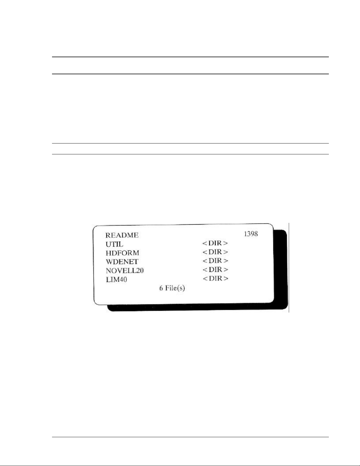
Figure 3-1 shows the main directory. The figure does not include dates and times. The diskette
may include additional files and deletions. Refer to the README file for explanations.
Figure 3-1: Utilities Main Directory
View the README file for a brief description of the setup and utility programs. Enter:
A>TYPE README <Enter>
The <DIR> entries in Figure 3-1 are subdirectories. Access these sub-directories by entering CD\
followed by the subdirectory name. For example, to access the hard disk formatting programs,
enter:
A> CD\HDFORM <Enter>
The following sections describe the various subdirectories.
PowerFLEX Users Manual 3-1
Page 20

Using the Utilities Diskette UTIL subdirectory
UTIL subdirectory
The UTIL subdirectory contains the hard disk Park & Ride program, PARKIDE, and a diskcaching program called SpeedRead. The following subsections describe these very important
utilities programs.
PARKIDE
PARKIDE is a park and ride program designed to immobilize the hard disk’s head during
movement. It basically works on the same principle as a needle return on a stereo. When you use
PARKIDE, you lock the hard disk’s head into one position so it can’t damage your data files by
skipping across them during transportation. Imagine a needle bouncing across your favorite
record, and you’ll know why this feature has been included.
WARNING: The Park & Ride utility program must be activated every time you transport your
PowerFlex. ALR recommends that you use this program regardless of the length of distance that
the PowerFlex will be moved.
To activate PARKIDE, follow this procedure:
1. Insert the PowerFlex Utility Diskette into drive A:.
2. Type:
A>CD\UTIL <Enter>
A>PARKIDE
3. Turn your system OFF. DO NOT touch any keys on your keyboard as this will deactivate
PARKIDE.
4. After you have moved your PowerFlex, to reactivate the hard disk, simply turn your system
back on.
Speed Read
Also included in the PowerFlex subdirectory UTIL is a program called SpeedRead. SpeedRead is
a disk-caching program that speeds up the hard disk access rate. As the system is used,
SpeedRead monitors how often certain parts of the disk are used and copies the most recently
used parts into its internal buffers. If the CPU attempts to read the data again, SpeedRead
retrieves the data from its buffers instead of the disk, thus speeding the transfer of data.
To learn more about this program and how to use it, read the README file and the SR.TXT file
on the PowerFlex Utilities Diskette in the subdirectory UTIL. The SR.TXT file contains a brief
usage guide that will explain how to use SpeedRead. To access the README and SR.TXT files,
or to print the SR.TXT file, follow the procedures below.
PowerFLEX Users Manual 3-2
Page 21

Using the Utilities Diskette UTIL subdirectory
1. Place the PowerFlex Utilities diskette into drive A:.
2. To read the README file, type:
A>CD\UTIL <Enter >
A>DIR <Enter>
A>TYPE README <Enter>
3. To read the SpeedRead usage guide, type:
A>MORE < SR.TXT <Enter>
The above command will move you through the usage guide one page at a time. To move
down to the next screen, press:
<Enter>
4. To print the SpeedRead usage guide, make sure you’re in the UTIL sub-directory, then type:
A>PRINT SR.TXT <Enter>
HDFORM subdirectory
The HDFORM subdirectory contains the WDFMT program, a versatile formatting utility that
performs a low-level format and surface analysis of the ALR high-performance hard disk drives.
Access the HDFORM subdirectory and view the README file by entering:
A>CD\HDFORM <Enter>
A>DIR <Enter>
A>TYPE README <Enter>
To run WDFMT you would then enter:
A> WDFMT <Enter>
The hard disk is now ready to be partitioned and formatted for DOS. See the section entitled
Initializing the hard disk drive in Chapter 2.
WDENET subdirectory
The WDENET subdirectory contains two versions of the Western Digital (WD) Ethernet driver
necessary for installing the LAN adapter boards. Version 2.0A contains the driver compatible
PowerFLEX Users Manual 3-3
Page 22

Using the Utilities Diskette WDENET subdirectory
with Novell’s NetWare v2.0a and version 2.1x contains the driver compatible with Novell’s
NetWare v2.11 and v2.12. The README file describes the two versions and details the
procedures for using the drivers. Follow the appropriate README file for installation
instructions on each version.
Access the WDENET subdirectory by entering:
A>CD\WDENET <Enter>
A>DIR <Enter>
From the WDENET subdirectory, access the V2.0A subdirectory and view the README file by
entering:
A>CD\V2.0A <Enter>
A>DIR <Enter>
A>TYPE README <Enter>
Similarly, view the README file from the V2.1x subdirectory by entering:
A>CD\V2.1x <Enter>
A>DIR <Enter>
A>TYPE README <Enter>
NOVELL20 subdirectory
This subdirectory contains instructions to enable the ALR hard disk drives to run using NetWare
v2.0a and v2.1. The README file contains these instructions.
Access the NOVELL20 subdirectory and view the README file by entering:
A>CD\NOVELL20 <Enter>
A>DIR <Enter>
A>TYPE README <Enter>
LIM40 subdirectory
This subdirectory contains the Expanded Memory Specification (EMS) device driver. The EMS
driver is loaded at boot up by the CONFIG.SYS file. The EMS device driver must be used in
conjunction with the 640K - 1024K Relocation feature and the EMS Memory feature in the
PowerFLEX Users Manual 3-4
Page 23

Using the Utilities Diskette LIM40 subdirectory
SETUP program. See Chapter 2 for further information.
Access the LIM40 subdirectory and view the README file by entering:
A>CD\LIM40 <Enter>
A>DIR <Enter>
A>TYPE README <Enter>
PowerFLEX Users Manual 3-5
Page 24

Chapter 4, Basic System Configurations
This chapter describes the hardware configurations for the PowerFlex 286 motherboard and
embedded hard disk drive. The basic 286 configurations will remain the same when you plug in
a PowerFlex 386SX or i486 Module. In fact, in an effort to keep upgrade costs as low as
possible, neither of the PowerFlex 386SX or i486 Modules contain memory chips. When you
upgrade to a 386SX or i486 system, the ALR PowerFlex 386SX and i486 Modules will use the
memory on the PowerFlex 286 motherboard.
Opening up the system unit
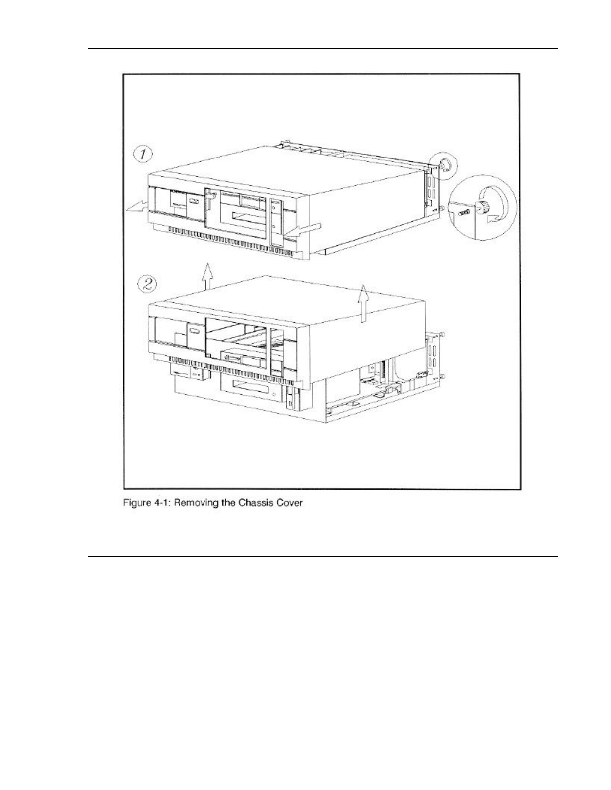
Open the system unit by following the procedure below and referring to Figure 4-1.
BE SURE THAT THE POWER SWITCH IS OFF AND THE POWER CORD IS REMOVED
FROM THE SYSTEM UNIT. Turn off any other equipment connected to the computer.
Installing any component while the power is on can permanently damage your computer and its
components.
1. Remove the four thumbscrews from the back panel by turning the screws counterclockwise.
Slide the cover towards you, approximately ¼-inch.
2. Lift the chassis cover straight up, and carefully lift it off.
PowerFLEX Users Manual 4-1
Page 25
Basic System Configuration Opening up the system unit
Configuring the PowerFlex motherboard
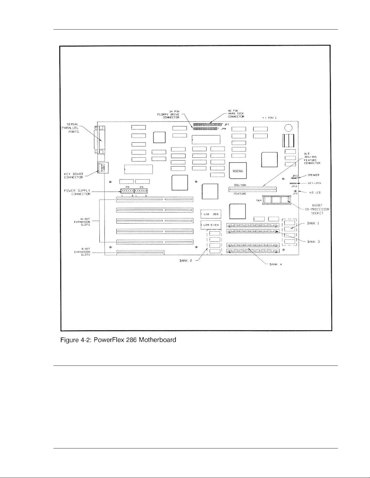
Figure 4-2 shows the location of various components on the PowerFlex 286 motherboard. This
six-slot motherboard has a bus speed of’ 8-MHz and contains one serial port, one parallel port,
and circuitry for the floppy and hard disk controllers. The following subsections describe the
memory configuration and the serial port, parallel port, floppy disk and hard disk controllers.
PowerFLEX Users Manual 4-2
Page 26
Basic System Configuration Configuring the PowerFlex motherboard
Memory installation and configuration
The PowerFlex 286 motherboard can have a maximum 5-MB onboard memory. The standard
1-MB 286 motherboard consists of eight 256K x 4 DRAMs located in Banks 1 and 2. DRAMs
used in the PowerFlex must be 256-KB x 4 page mode with access times of l00ns. Banks 3 and 4
consist of two rows of Single Inline Memory Modules (SIMMs) connectors each. SIMMs used
in the PowerFlex must be 1-MB x 9 or 256K x 9 page mode with access times of 80ns or l00ns.
Banks 1 and 2 must be filled before you can add SIMMs in Banks 3 and 4. See Figure 4-1 for
bank locations and Table 4-1 for memory configurations.
PowerFLEX Users Manual 4-3
Page 27
Basic System Configuration Configuring the PowerFlex motherboard
Table 4-1: Standard FlexCache 286 Memory Configuration
BANK 1 BANK 2 BANK 3 BANK 4
TOTAL
MEMORY
DRAM Type Memory Module Type
256Kx4 256Kx4 - - - - - - 1-MB
256Kx4 256Kx4 256Kx9 - - - 1.5-MB
256Kx4 256Kx4 256Kx9 256Kx9 2-MB
256Kx4 256Kx4 1MBx9 - - - 3-MB
256Kx4 256Kx4 1MBx9 1MBx9 5-MB
DRAM chips must be page mode and have a speed of 80ns or 100ns.
Installing SIMMs
Follow the procedure below for installing additional SIMMs:
1. Open the system unit as described previously in this chapter.
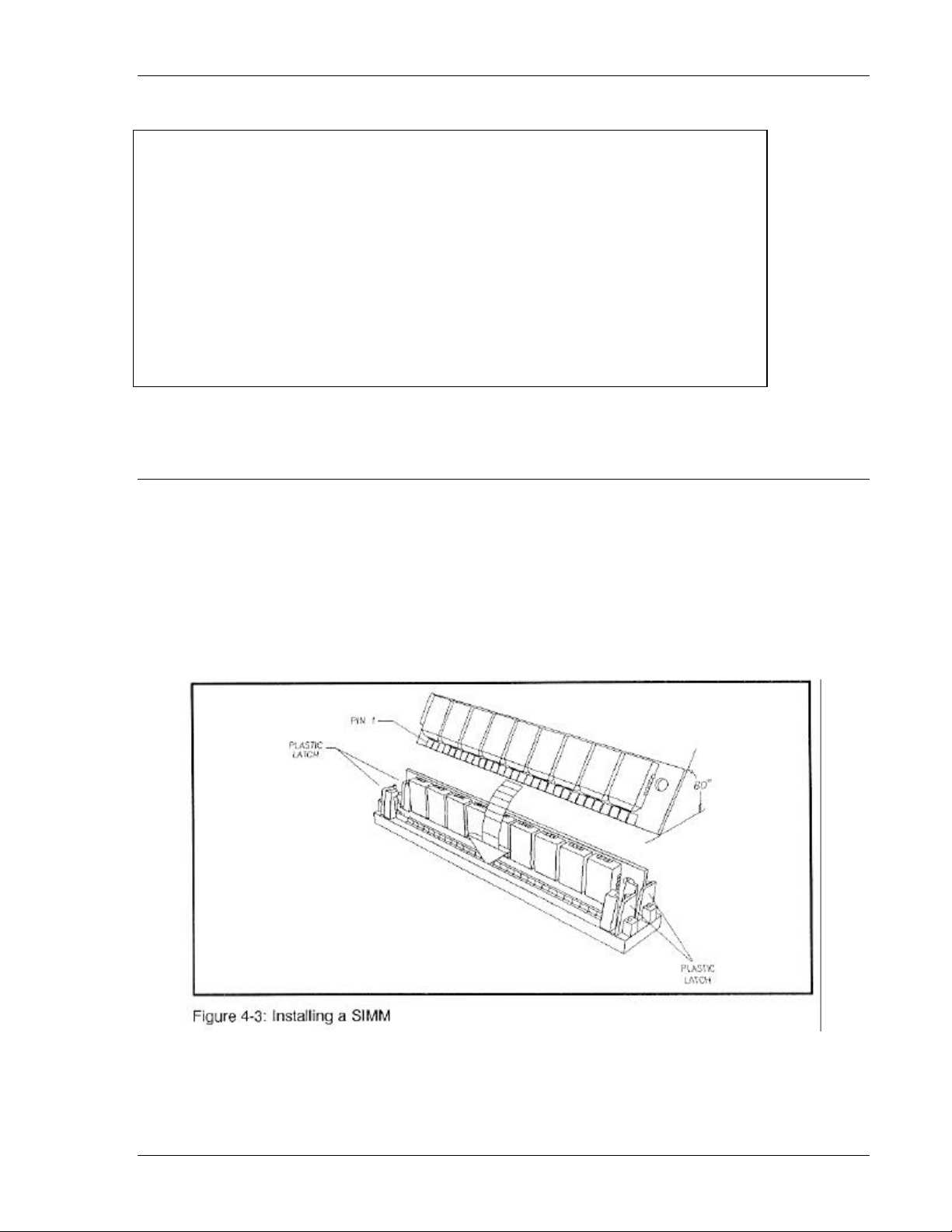
2. Insert a SIMM into the proper socket (per Table 4-1) at a 60-degree angle as shown in Figure
4-3.
3. Press the SIMM firmly into the socket until it clicks into place.
4. Pull the plastic latches on each end outward, rotate the SIMM until it is vertical, and release
the plastic latches.
PowerFLEX Users Manual 4-4
Page 28

Basic System Configuration Configuring the PowerFlex motherboard
(Duplicate)
FF0000-FFFFFF
NOTE: Inspect the SIMMs to make sure they are all the same depth within their sockets. If they
are not, they are not properly installed and you will get an error message.
5. Repeat steps 2-4 above to install other SIMMs.
6. Once you have made the desired memory expansion, run the SETUP program as described in
Chapter 2 to account for the new memory. This will be done in the EMS RAM/ROM SWAP
screen and will include the following steps:
• EMS Memory must be enabled
• 640 - 1024K Relocation must be DISABLED
• The EMS device driver in LIM40 must be activated
• The EMS Memory Size must be changed
NOTE: To configure the PowerFlex beyond 5-MB of memory, you will need to purchase thirdparty 16-bit memory expansion cards.
Removing SIMMs
Follow the procedure below to remove a SIMM from the PowerFlex:
1. Insert a thin screwdriver blade between the SIMM and one of the latches (as shown in Figure
4-2) holding the SIMM in place.
2. Gently press the latch down and away from the SIMM. DO NOT FORCE THE LATCH AS
THEY ARE FRAGILE AND MAY BREAK OFF.
3. Once all of the latches have been released, lift the SIMM out of its socket.
EPROM configuration
The system BIOS consists of two 32-KB by eight 27256 EPROMs at locations shown in Figure
4-1. Odd addresses reside in U38 and even addresses reside in U39. The system BIOS resides in
the system memory address space from 0F0000 to 0FFFFF. The system BIOS uses 27256
EPROMs for 64-KB of system ROM. Table 4-2 summarizes the EPROM configuration for the
286 motherboard.
Table 4-2: 286 CPU BIOS EPROM Assignments
EPROM TYPE
CODE ADDRESS
ASSIGNMENTS
EVEN
BIOS
ODD
BIOS
64K System BIOS 0F0000*-0FFFFF U39 U38
U39 U38
* factory setting
PowerFLEX Users Manual 4-5
Page 29

Basic System Configuration Configuring the PowerFlex motherboard
286 motherboard connector pinouts
Table 4-3 describes the output connectors for the 286 CPU.
Table 4-3: 286 Motherboard Output Connectors
Keyboard Speaker Front Panel
J8
FUNCTION
JP13
FUNCTION
JP14
FUNCTION
1
Clock
1
Speaker
1
LED
2 Data 2 N/C 2 N/C
3
4
5
N/C
Ground
+5V
3
4
Ground
+5V
3
4
5
N/C
N/C
Ground
ROM-to-RAM swapping
The PowerFlex may swap the content of the ROM BIOS into the system RAM memory for faster
execution of the BIOS code. This feature is controlled in the second screen of the ROM BIOS
Setup program (EMS RAM/ROM SWAP Screen).
Serial port configuration
The PowerFlex 286 motherboard includes one serial port (see Figure 4-1). The serial port is a
standard DB25 male connector and is fully IBM-plug compatible. You can configure the serial
port for either COM1 or COM2 via the Soft Switch Options Screen of the SETUP program (see
Chapter 2 for details).
Parallel port configuration
The PowerFlex 286 motherboard contains one parallel port (see Figure 4-1). You can configure
the parallel port for either LPT1 or LPT2 via the Soft Switch Options Screen of the SETUP
program (see Chapter 2 for details). The parallel port is a standard DB25 female connector and is
fully IBM-plug compatible.
Floppy disk controller configuration
The PowerFlex 286 motherboard includes an integrated floppy disk controller chip which
contains the circuitry and control functions for interfacing to two floppy disk drives. This IBM
PC/XT/AT-compatible chip supports 5¼-inch drives with 360-KB or 1.2-MB capacities and
3½-inch drives with 720-KB or 1.44-MB capacities.
PowerFLEX Users Manual 4-6
Page 30

Basic System Configuration Configuring the PowerFlex motherboard
Hard disk controller configuration
Like the floppy disk controller, the PowerFlex 286 motherboard also includes an integrated hard
disk controller logic which contains the circuitry and control functions for interfacing to two hard
disk drives. This logic supports two 3-1/2 inch AT-type embedded hard disk drives up to
528-MB.
PowerFLEX Users Manual 4-7
Page 31

Chapter 5, Options
This chapter describes the installation and setup procedures for options compatible with the
PowerFlex. Optional boards and equipment include the following:
Hard Disk Drives. The PowerFlex comes standard with an embedded 40-MB (< 40ms)
AT-interface drive with support for a second embedded 40-MB hard disk drive. Hard disk
controller functions are embedded on the hard disk drive.
Floppy Disk Drives. In addition to the standard 3½-inch floppy disk drive, the PowerFlex
chassis can accommodate two 5¼-inch 1.2-MB and one 3½-inch 1.44-MB floppy disk drives.
PowerFLEX Users Manual 5-1
Page 32

Options Installing new boards
Installing new boards
You can easily install expansion boards into the PowerFlex motherboard. Remove four
thumbscrews from the rear of the chassis by turning the screws counterclockwise. Figure 1-2
shows the expansion slots available for additional boards. Follow the procedure below for
installing new boards:
1. Configure the boards before you install them in the expansion slots. The sections in this
chapter describe the appropriate configuration for various optional boards. To prevent
damage to expansion cards, always hold them by the edges. To avoid electric static build-up,
never lay expansion cards on carpeting. To discharge static electricity from your body, touch
the metal cabinet of any electrical equipment that is plugged into a three-prong grounded
outlet.
2. Remove the screw that holds the expansion slot cover in place. Save the screw for board
installation.
3. Hold the expansion board by its top edge or upper corners and insert it into the appropriate
slot.
4. Make sure a full-sized board mounts firmly into the card guides at the front of the chassis.
5. Install the reserved mounting screw to secure the expansion slot plate in place.
Storage devices
The following subsections describe the installation procedures and configuration of the various
storage devices available for the PowerFlex. Figure 1-2 provides an overall view showing these
optional storage devices.
Hard disk drives
The PowerFlex chassis can accommodate one other embedded 40-MB hard disk drive in addition
to the hard disk drive it is shipped with. If you purchase a second hard disk drive through ALR
you will receive a high-performance embedded 3-1/2 inch 40-MB <40ms 1:1 interleave hard
disk drive that supports one type of drive parameter configuration: 17 sectors, 5 heads, 977
cylinders.
If you choose to purchase one of these optional drives as a second hard disk drive, make sure you
purchase and/or receive the following:
• An embedded hard disk drive
• Cabling for two-drive support
PowerFLEX Users Manual 5-2
Page 33
Options Storage devices
• A user’s manual for the second embedded hard disk drive detailing its installation and
configuration
Installing and configuring an embedded hard drive
If you install a second embedded 40-MB hard disk drive, both drives may be accessed via a
common two-drive interface cable using the same range of I/O addresses. The drives are
jumpered as drive 0 or 1 and have a master/slave relationship. Drive 0 is the master drive, and
drive 1 the slave. In a single drive system, no jumper is required; the unit will default to drive 0.
In a two drive system, drive 0 should be jumpered as “master” and drive 1 should be jumpered as
“slave.”
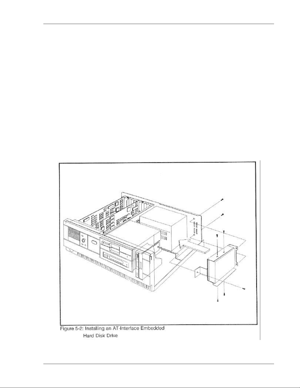
Figure 5-2 shows how to install an AT-interface embedded hard disk drive into a PowerFlex
chassis. Connect the 40-pin ribbon cable between the hard disk drive housing and the JP7
connector on the PowerFlex 286 motherboard. Be sure to align pin 1 (same side as red piping) on
the cable to pin 1 (where the notch is) on the connector. If a second hard disk drive is installed, it
must be daisy-chained to the first hard disk drive via the 40-pin connector on the above
mentioned cable.
PowerFLEX Users Manual 5-3
Page 34

Options Storage devices
To configure the system for an embedded hard drive, run the SETUP program as described in
Chapter 2 and set the drive type according to the type listed on a sticker on the drive. Thereafter,
perform the FDISK and FORMAT commands, as described in the section entitled Initializing the
hard disk drive in Chapter 2.
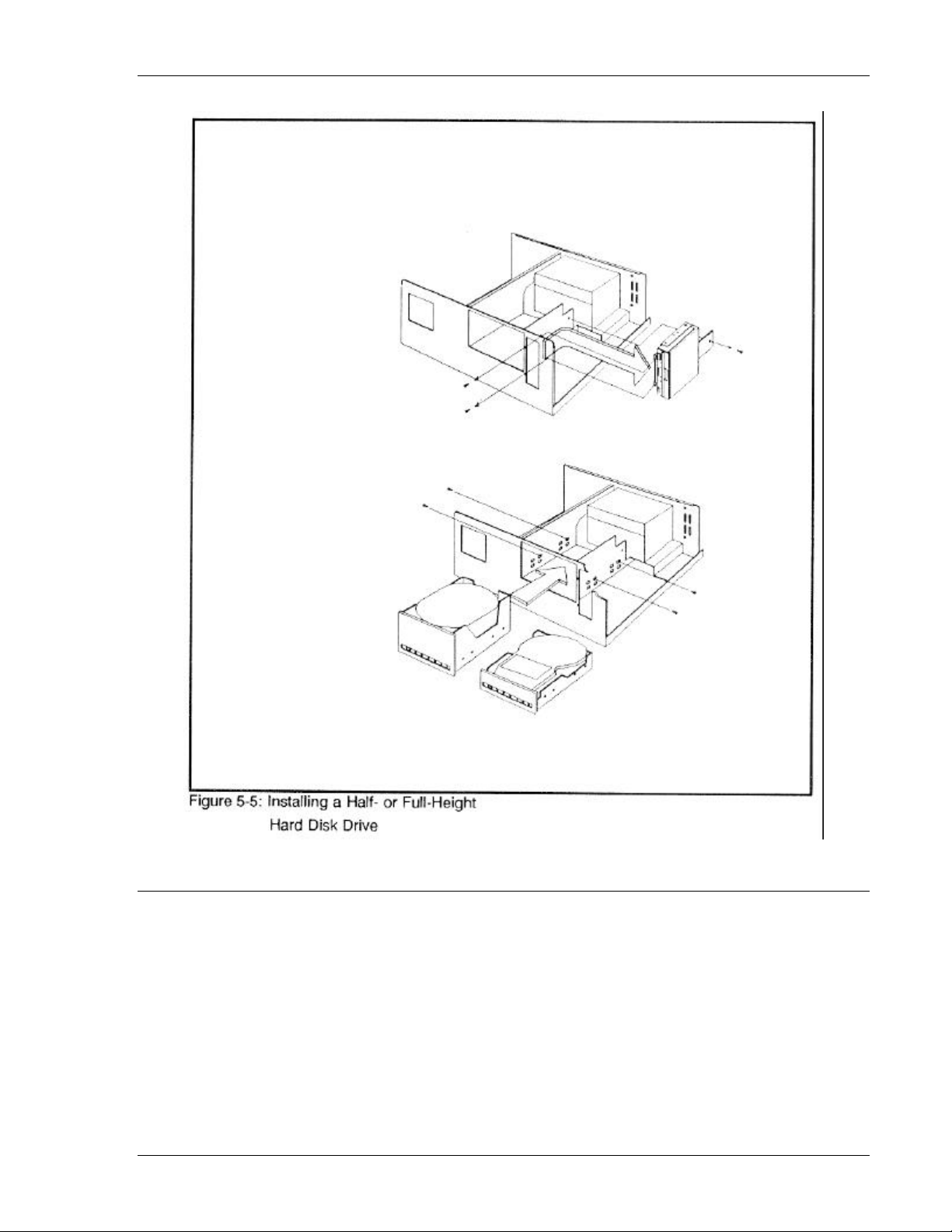
Installing and configuring a half- or full-height hard disk drive
Before installing a half- or full-height hard disk drive, remove the 3½-inch floppy drive that
comes standard with the system. Re-install the floppy drive after installing the hard drive. See
Figure 5-5 for installation procedures. Configure the system by running the SETUP program as
described in Chapter 2.
NOTE: If you install a half- or full-height hard disk drive, an appropriate optional hard disk
controller card will be required. Refer to the hard disk drive’s user’s manual for more
information.
PowerFLEX Users Manual 5-4
Page 35
Options Storage devices
Floppy disk drives
The PowerFlex chassis can accommodate two 5¼ or 3½-inch floppy devices. The following
subsections describe how to install and configure these drives.
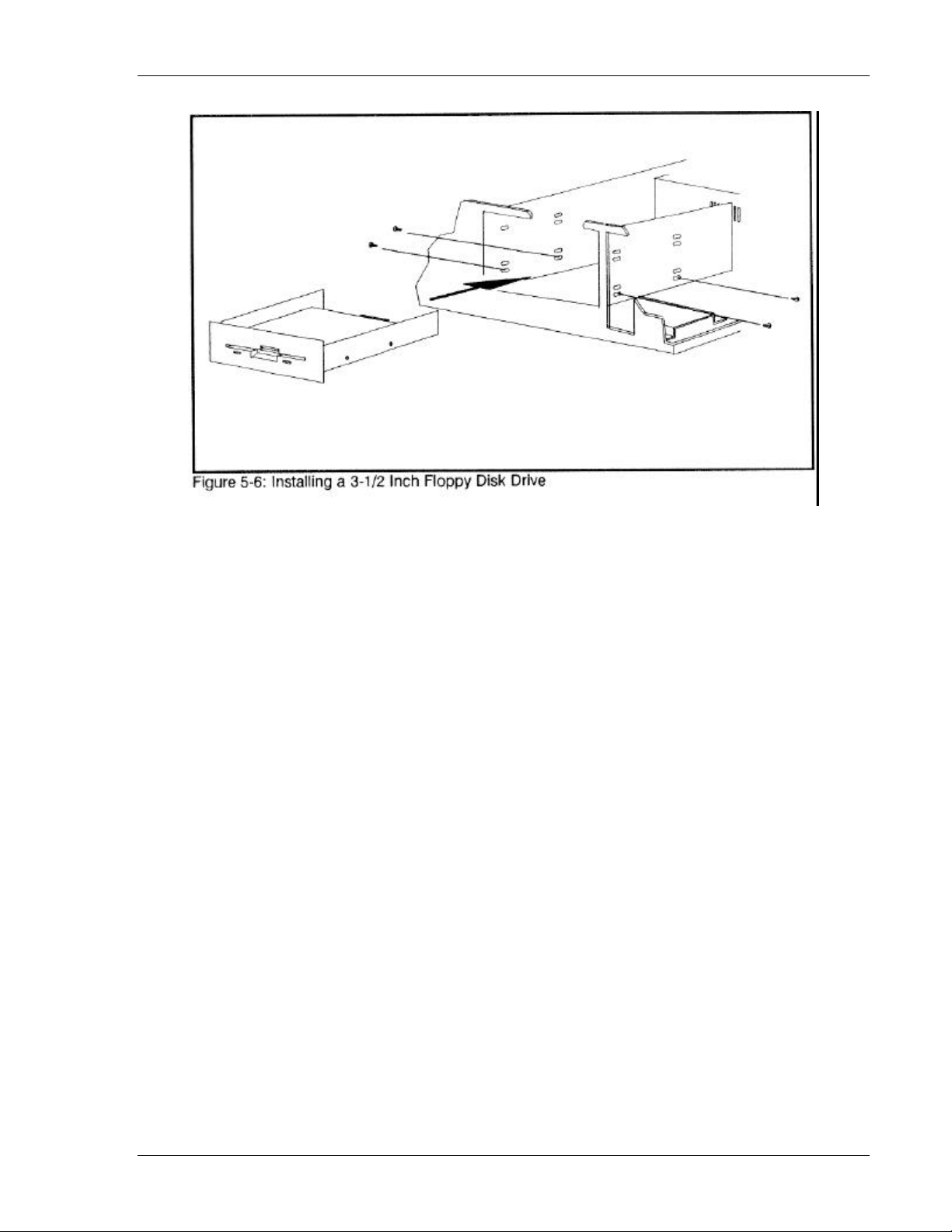
3½-inch floppy disk drives
Figure 5-6 shows how to install a 3½-inch floppy disk drive or, refer to the manual that
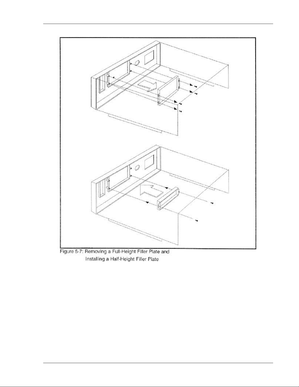
accompanied your 3½-inch floppy drive kit. Additionally, the 3½-inch floppy disk drive kit
comes with a half-height filler plate. Figure 5-7 shows how to remove the full-height filler plate
that comes with the system and how to install the half-height filler plate that comes with the kit.
PowerFLEX Users Manual 5-5
Page 36
Options Storage devices
PowerFLEX Users Manual 5-6
Page 37
Options Storage devices
To cable the drive, connect the floppy disk cable by aligning pin 1 (same side as the red piping)
on the 34-pin ribbon cable to the 286 motherboard at JP8’s pin 1 (where the notch is). Connect
the other end of the cable in the same manner to pin 1 on the floppy disk drive. Connect the
power cable to the power connector and plug in all other cords and cables.
Run the SETUP program and change the system configuration to include a 3½-inch floppy disk
drive (see Chapter 2). The 3½-inch inch floppy disk drive is a 1.44-MB drive with a 2-MB media
hold sensor. The drive can read/write 720-KB or 1.44-MB diskettes; however, you must use the
right medium according to the SETUP configuration. Default is set for a 1.44-MB drive. For
example, if you use a 1-MB diskette and format with the standard default setup, DOS format will
display an error.
PowerFLEX Users Manual 5-7
Page 38
Options Storage devices
There are two ways to solve this formatting problem:
1. Use a 2-MB media.
2. Format DOS with 720-KB option parameters
A>FORMAT A:/T:80/n:9/S <Enter>
5¼-inch floppy disk drives
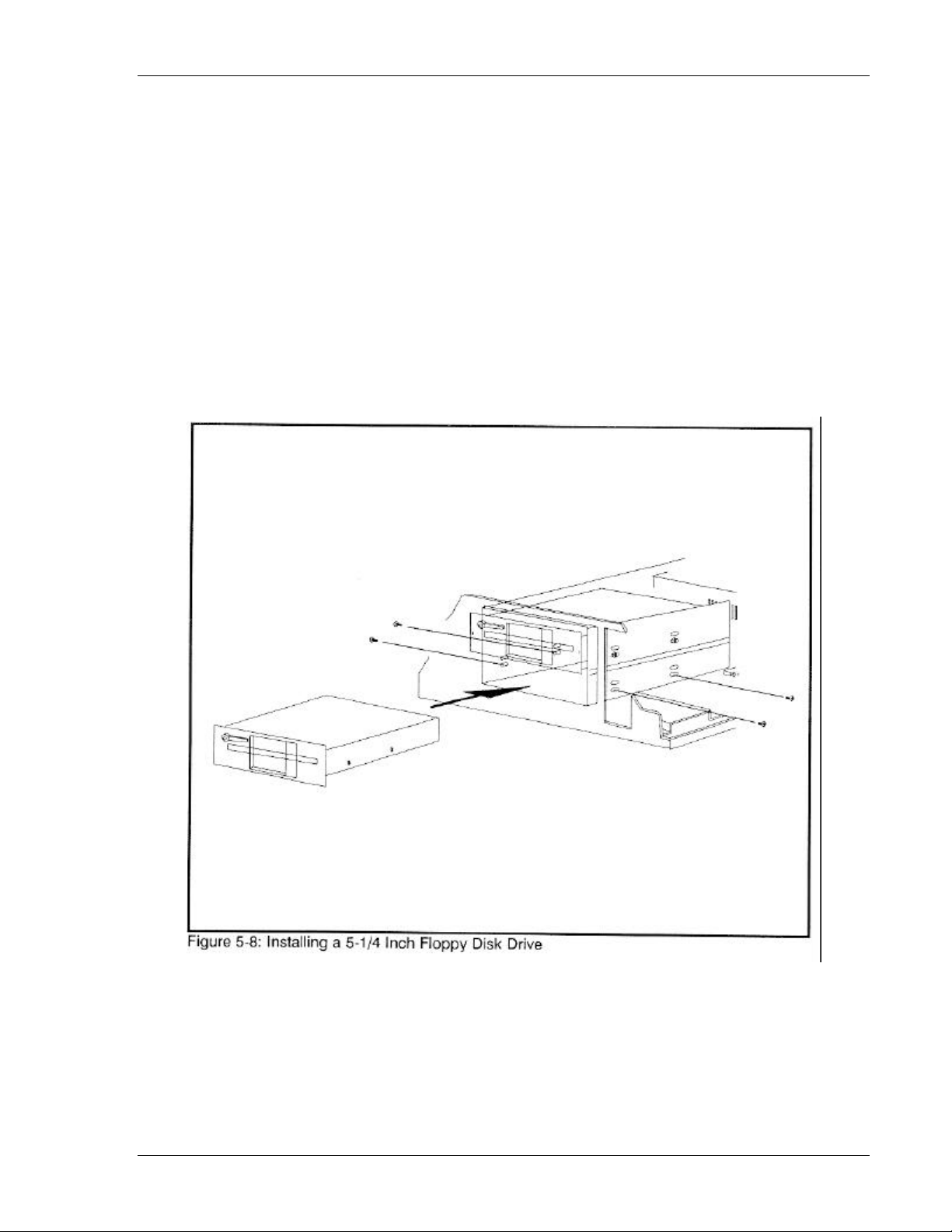
Figure 5-8 shows how to install a 5¼-inch floppy disk drive or, refer to the manual that
accompanied your 5¼-inch floppy drive kit. Additionally, the 5¼-inch floppy disk drive kit
comes with a half-height filler plate. Figure 5-7 shows how to remove the full-height filler plate
that comes with the system and how to install the half-height filler plate that comes with the kit.
PowerFLEX Users Manual 5-8
Page 39

Options Storage devices
To cable the drive, connect the floppy disk cable by aligning pin 1 (same side as the red piping)
on the 34-pin ribbon cable to the 286 motherboard at JP8’s pin 1 (where the notch is). Connect
the other end of the cable in the same manner to pin 1 on the floppy disk drive. Connect the
power cable to the power connector and plug in all other cords and cables.
Run the SETUP program and change the system configuration to include a 5¼-inch floppy disk
drive (see Chapter 2).
PowerFLEX Users Manual 5-9
Page 40

Appendix A, Error Messages
The power-on self test displays messages when it detects nonfatal on board or off board failures.
There are two types of error messages:
• Nonfatal Errors display information on your monitor
• Fatal System Board Error Beep Codes signal an error condition when a message cannot be
displayed on your monitor
For recurring problems do the following:
• Call your nearest authorized ALR dealer.
• Call the ALR Technical Support at (714) 458-0863.
Remember, DO NOT send any equipment without a Return Material Authorization (RMA) and
original packaging.
Nonfatal errors
This section lists messages that may be displayed when your computer boots up. Variable [xxx]
items differ from message to message. Possible explanations and solutions are also provided
here.
PowerFLEX Users Manual A-1
Page 41

Error Messages Nonfatal errors
[xxx] Base Memory, [xxx] Expansion
Explanation:
This message is for your information only.
Solution:
No action necessary.
Checking RAM on disk controller....
Error found on controller RAM at offset location 3800
[xxx] Option ROM bad checksum = [xxx]
Memory Parity interrupt at [xxx].
Type (S)hut off NMI, (R)eboot, other keys to continue Strike the Fl key to continue
Explanation:
Your setup configuration is incorrect.
Solution:
Type S at the system error prompt. Insert the utilities diskette and press F1 to reboot. Run the
SETUP program as described in Chapter 2. Check the hard disk controller to make sure it is
inserted in the slot properly.
Checksum error on extended CMOS.
Explanation:
The data in extended CMOS is invalid.
Solution:
Run the SETUP program as described in Chapter 2 of this manual.
Decreasing available memory
Explanation:
Your system’s RAM chips may be defective or the pins may be bent.
Solution:
Check the RAM chips and make sure they’re properly inserted into their sockets. Replace if
necessary.
PowerFLEX Users Manual A-2
Page 42

Error Messages Nonfatal errors
Diskette drive 0 seek to track 0 failed
Explanation:
Your system’s configuration is incorrect; the actual floppy drive in your system is different from
that specified in your SETUP configuration. The floppy drive cable may not be properly inserted.
Solution:
Check your SETUP configuration and make sure the correct drive is selected. Make sure the
floppy drive cable is properly secured.
Diskette drive reset failed
Explanation:
Your system’s configuration is incorrect. The actual floppy drive in your system does not match
the one specified in your SETUP configuration or the floppy drive/cables may be defective.
Solution:
Check your SETUP configuration and make sure the correct drive is selected. Replace the
drive/cable.
Diskette read failed - strike F1 to retry boot
Explanation:
The floppy disk inserted in your drive is not a bootable disk, the jumper setting for your drive is
incorrect, or the switch setting is incorrect for your controller card.
Solution:
Make sure that your boot disk contains a file called COMMAND. COM or check the
jumper/switch settings for your drive or controller card, respectively. Press F1 to reboot.
Display adapter failed; using alternate
Explanation:
The video card installed in your system is different from the video switch setting on the system
board.
Solution:
Check the video switch/jumper setting, SW1, on the system board and make sure it’s OFF/OUT
for MGA and ON/IN for CGA.
Gate A20 failure
Explanation:
You have an XT keyboard connected to your AT system.
Solution:
If your keyboard was not provided by ALR, check the switch at the bottom of your keyboard and
make sure it is pointing to “AT.” If the message persists, replace the keyboard.
PowerFLEX Users Manual A-3
Page 43

Error Messages Nonfatal errors
Hard disk controller failure
Explanation:
The hard disk cable may not be properly secured or the hard disk controller card may be
defective.
Solution:
Make sure the hard disk cable is properly secured or replace the hard disk controller card.
Hard disk failure
Explanation:
The hard disk may not have been low-level formatted, the SETUP configuration does not match
the type of hard disk actually installed in your system, or the hard disk controller may be
defective.
Solution:
Run the SETUP program, described in Chapter 2 of this manual, and make sure your
configuration is correct. Contact your authorized ALR dealer for assistance in performing a lowlevel format or for replacing the controller card.
Hard disk failure - strike F1 to retry boot
Explanation:
The hard disk or hard disk controller may be defective, or the DOS FORMAT has not yet been
performed.
Solution:
Press F1 to reboot. If the message persists, replace the hard disk controller card. Perform an
FDISK and a DOS FORMAT as explained in Chapter 2 of this manual.
Invalid configuration information - please run SETUP program
Explanation:
The information stored in CMOS memory does not match your system’s actual configuration
during power-up.
Solution:
Check your system’s configuration by running the SETUP program as described in Chapter 2 of
this manual.
Keyboard clock line failure
Explanation:
The keyboard or a keyboard chip may be defective.
PowerFLEX Users Manual A-4
Page 44

Error Messages Nonfatal errors
Solution:
If your keyboard was not provided by ALR, check the bottom of the keyboard and make sure it is
set to "AT" mode or try another keyboard. Contact your authorized ALR dealer for assistance in
replacing the keyboard chip.
Keyboard controller failure
Explanation:
A keyboard chip or the keyboard may be defective.
Solution:
If your keyboard was not provided by ALR, check the bottom of the keyboard and make sure it is
set to "AT" mode or try another keyboard. Contact your authorized ALR dealer for assistance in
replacing the keyboard chip.
Keyboard data line failure
Explanation:
A keyboard chip or the keyboard may be defective,
Solution:
If your keyboard was not provided by ALR, check the bottom of the keyboard and make sure it is
set to "AT" mode or try another keyboard. Contact your authorized ALR dealer for assistance in
replacing the keyboard chip.
Keyboard stuck key failure
Explanation:
One of the keyboard keys may be jammed.
Solution:
Push the jammed key to release it or replace the keyboard.
Memory address line failure at [xxx], read [xxx] expecting [xxx]
Explanation:
Your system’s memory chips may be defective or the pins may be bent.
Solution:
Check the memory chips and make sure they’re properly inserted into their sockets. Replace if
necessary.
Memory high address line failure at [xxx], read [xxx] expecting [xxx]
Explanation:
Your system’s memory chips may be defective or the pins may be bent.
PowerFLEX Users Manual A-5
Page 45

Error Messages Nonfatal errors
Solution:
Check the memory chips and make sure they’re properly inserted into their sockets. Replace if
necessary.
Memory test terminated by keystroke
Explanation:
During power-up, a key was pressed while the system was running the memory test.
Solution:
No action necessary.
Memory write/read failure at [xxx], read [xxx] expecting [xxx]
Explanation:
Your system’s RAM chips may be defective or the pins may be bent.
Solution:
Check the RAM chips and make sure they’re properly inserted into their sockets. Replace if
necessary. Note: Sometimes a defective video card may cause this problem.
No boot device available - strike Fl to retry boot
Explanation:
There’s no bootable file on the floppy disk, the diskette or the floppy disk controller may be
defective.
Solution:
Make sure the boot disk contains the COMMA ND.COM file. Check that the floppy disk cont
roller jumper setting is set for enabling the floppy disk. Press F1 to reboot. If the message
persists, replace the floppy disk controller.
No boot sector on hard disk - strike Fl to retry boot
Explanation:
There’s no bootable file on the hard disk.
Solution:
Press F1 to reboot. If the message persists, format the hard disk as follows:
SYS C: <enter>
COPY COMMAND.COM C: <enter>
If the message persists, format the hard disk as follows:
FORMAT C:/S <enter>
PowerFLEX Users Manual A-6
Page 46

Error Messages Nonfatal errors
Not a boot diskette - try F1 to retry boot
Explanation:
There’s no bootable file on the boot disk or your system’s SETUP configuration does not match
the actual floppy drive on the system.
Solution:
Make sure the boot disk contains the COMMAND.COM file. Press F1 to reboot. Run the SETUP
program, described in Chapter 2 of this manual, to configure the correct floppy drive.
No timer tick
Explanation:
Your system’s timer circuitry or your system’s BIOS chips may be defective or it’s an older
version.
Solution:
Contact your authorized ALR dealer for assistance.
[xxx] Optional ROM bad Checksum = [xxx]
Explanation:
An optional BIOS card may be defective.
Solution:
Contact your authorized ALR dealer for assistance.
Phoenix ROM BIOS Version x.xx
Copyright 198x Phoenix Technologies Ltd.
All Rights Reserved
Explanation:
This message displays the version of the ROM BIOS installed in your system.
Solution:
No action necessary.
Shutdown failure
Explanation:
Your system’s hardware circuitry has malfunctioned.
Solution:
Contact your authorized ALR dealer for assistance.
Strike the Fl key to continue
PowerFLEX Users Manual A-7
Page 47

Error Messages Nonfatal errors
Explanation:
The system cannot locate a bootable file from the floppy or hard disk.
Solution:
Insert a bootable DOS diskette into the floppy drive. Press F1 to continue the boot.
Time of day clock stopped
Explanation:
A clock chip may be defective or the battery may be discharged.
Solution:
Re-run the SETUP program (see Chapter 2) to get the time of day. If the problem persists,
contact your authorized ALR dealer.
Timer Chip counter 2 failed
Explanation:
Your system’s hardware circuitry has malfunctioned.
Solution:
Contact your authorized ALR dealer for assistance.
Timer of Interrupt Controller Bad
Explanation:
Your system’s hardware circuitry has malfunctioned.
Solution:
Contact your authorized ALR dealer for assistance.
Unexpected interrupt in protected mode
Explanation:
Your system’s hardware circuitry has malfunctioned.
Solution:
Contact your authorized ALR dealer for assistance.
PowerFLEX Users Manual A-8
Page 48

Error Messages Fatal system board error beep codes
Fatal system board error beep codes
If an error occurs when the monitor is not available to display the message, the self-test issues a
series of beeps to signal the error. The self-test does not issue a beep if a test is aborted while in
progress.
For example, a failure of bit 3 in the first 64-KB of RAM causes a 2-1-4 beep code (a burst of
two beeps, a single beep, and a burst of four beeps). Additionally, the self-test writes a value to
I/0 port 08H. This code enables debugging tools to help technical users identify the failed area.
Errors are either fatal (those that halt the system) or nonfatal (those that are not serious enough to
halt the system). Fatal errors contain the word “failure”.
Beep
Code
Description
080H
Code
none 80386 register test in progress 01H
1-1-3 Real-time clock write/read failure 02H
1-1-4 ROM BIOS checksum failure 03H
1-2-1 Programmable Interval Timer Failure 04H
1-2-2 DMA initialization failure 05H
1-2-3 DMA page register write/read failure 06H
1-3-1 RAM refresh verification failure 08H
none 1st 64-KB RAM test in progress 09H
1-3-3 1st 64-KB RAM chip or data line multi-bit 0AH
1-3-4 1st 64-KB RAM add/even logic failure 0BH
1-4-1 Address line failure 1st 64-KB RAM 0CH
1-4-1 Address line failure 1st 64-KB RAM 0CH
1-4-2 Parity failure 1st 64-KB RAM 0DH
2-1-1 Bit 0 1st 64-KB RAM failure 10H
2-1-2 Bit 1 1st 64-KB RAM failure 11H
2-1-3 Bit 2 1st 64-KB RAM failure 12H
2-1-4 Bit 3 1st 64-KB RAM failure 13H
2-2-1 Bit 4 1st 64-KB RAM failure 14H
2-2-2 Bit 5 1st 64-KB RAM failure 15H
2-2-3 Bit 6 1st 64-KB RAM failure 16H
2-2-4 Bit 7 1st 64-KB RAM failure 17H
2-3-1 Bit 8 1st 64-KB RAM failure 18H
2-3-2 Bit 9 1st 64-KB RAM failure 19H
2-3-3 Bit A 1st 64-KB RAM failure 1AH
2-3-4 Bit B 1st 64-KB RAM failure 1BH
2-4-1 Bit C 1st 64-KB RAM failure 1CH
2-4-2 Bit D 1st 64-KB RAM failure 1DH
2-4-3 Bit E 1st 64-KB RAM failure 1EH
2-4-4 Bit F 1st 64-KB RAM failure 1FH
3-1-1 Slave DMA register failure 20H
PowerFLEX Users Manual A-9
Page 49

Error Messages Fatal system board error beep codes
Beep
Code
Description
080H
Code
3-1-2 Master DMA register failure 21H
3-1-3 Master interrupt mask register failure 22H
3-1-4 Slave interrupt mask register failure 23H
none Interrupt vector loading in progress 25H
3-2-4 Keyboard controller test failure 27H
none Real-time clock power failure and checksum calculation in
28H
progress
none Real-time clock configuration validation in progress 29H
3-3-4 Screen memory test failure 2BH
3-4-1 Screen initialization failure 2CH
3-4-2 Screen retrace test failure 2DH
none Search for video ROM in progress 2EH
none Screen believed operable 30H
none Screen believed running with video ROM 30H
none Monochrome display believed operable 31H
none Color display (40 column) believed operable 32H
none Color display (80 column) believed operable 33H
PowerFLEX Users Manual A-10
Page 50
Appendix B, Hard Disk Drive Characteristics
Land-
Drive
Type
1 306 4 128 305 17 10.1
2 615 4 300 615 17 20.4
3 615 6 300 615 17 30.6
4 940 8 512 940 17 62.4
5 940 6 512 940 17 46.8
6 615 4 -1 615 17 20.0
7 462 8 256 511 17 30.6
8 733 5 -1 733 17 30.4.
9 900 15 -1 901 17 112.0
10 820 3 -1 820 17 20.4
11 855 5 -1 855 17 35.4
12 855 7 -1 855 17 49.6
13 953 7 -1 953 34 110.0
14 733 7 -1 733 26 65.0
16 953 5 -1 953 34 79
17 977 5 300 977 17 40.5
18 977 7 -1 977 17 56.7
19 1024 7 512 1023 17 59.5
20 823 10 -1 823 34 136.6
21 733 7 300 732 17 42.5
22 971 5 -1 971 26 61.0
23 820 6 -1 820 17 40.0
24 1024 7 -1 1024 34 119
25 1022 7 -1 1022 34 118
26 1024 4 -1 1023 17 34.0
27 1024 5 -1 1023 17 42.5
28 1024 8 -1 1023 17 68.0
29 615 4 612 615 26 31.2
30 1160 7 -1 904 26 103.0
31 989 5 128 989 17 41.0
32 1020 15 -1 1024 17 127.0
33 1024 9 -1 1024 17 76.0
34 966 9 -1 966 34 144.3
35 966 8 -1 966 34 128.2
36 1024 5 512 1024 17 42.5
37 1024 5 -1 1024 26 65.0
38 611 16 -1 612 63 300.7
39 654 16 -1 1630 63 321.0
Cylin-
ders Heads
Pre-
comp
ing
Zone
Sec-
tors
Size
(megs)
PowerFLEX Users Manual B-1
Page 51

Hard Disk Drive Characteristics
Land-
Drive
Type
Cylin-
ders Heads
Pre-
comp
ing
Zone
Sec-
tors
Size
(megs)
40 642 16 -1 1778 63 315.0
41 917 15 -1 918 17 114.1
42 1023 15 -1 1024 17 127.3
43 823 10 512 823 17 68.3
44 820 6 -1 820 17 40.0
45 1024 8 -1 1024 17 68.0
46 1024 7 -1 1024 26 91.0
47 288 16 -1 1224 63 141.0
48 0 0 0 0 0 0
49 0 0 0 0 0 0
• Drive type numbers not assigned are reserved for future use.
• Drive types 48 and 49 are user-definable. That is, you can change the parameters according
to your drive specification. See Chapter 2 for details.
• To see this table during SETUP, move the cursor to Hard Disk C: and press Fl.
PowerFLEX Users Manual B-2
Page 52
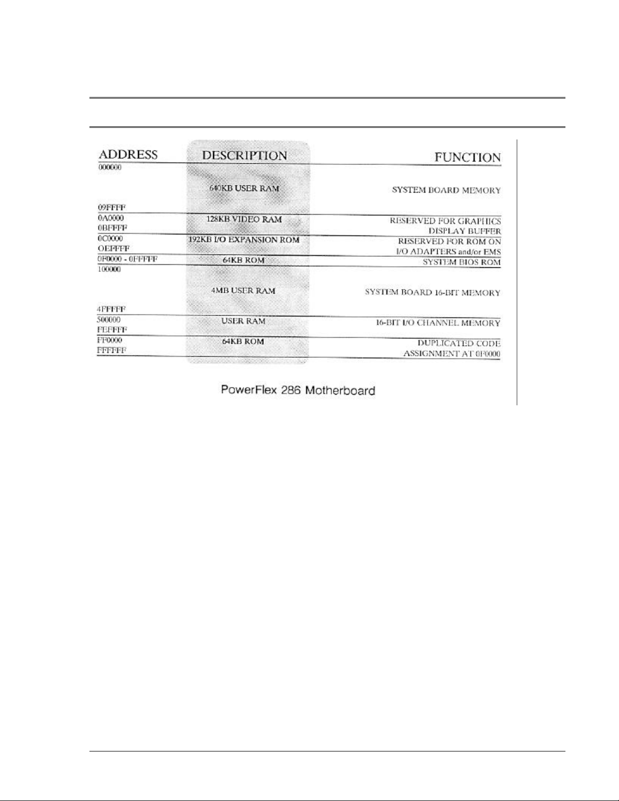
Appendix C, System Board Memory Map
PowerFLEX Users Manual C-1
Page 53

Appendix D, I/O Address Map
Address Port
000-01F DMA Controller #1
020-03F Interrupt Controller #1
040-05F Timer
060-06F Keyboard
070-07F Real-time Clock, NMI
080-09F DMA Page Register
0A0-0BF Interrupt Controller #2
0C0-0DF DMA Controller #2
0F0 Clear Math Coprocessor Busy
0F1 Reserved
0F8-0FF Math Coprocessor
107 Reserved for I/O Setup Configuration
1F0-1F8 Fixed Disk
200-207 Game I/O
278-27F Parallel Printer Port #2
2F8-2FF Serial Port #2
300-31F Prototype Card
360-36F Reserved
378-37F Parallel Printer Port #1
380-38F SDLC, bisynchronous #2
3A0-3AF Bisynchronous #1
3B0-3BF Monochrome Display and Printer Adapter
3C0-3CF Reserved
3D0-3DF Color/Graphics Monitor Adapter
3F0-3F7 Floppy Diskette Controller
3F8-3FF Serial Port #1
PowerFLEX Users Manual D-1
Page 54

Appendix E, Low-Level Formatting
THE HARD DISK DRIVE HAS BEEN LOW-LEVEL FORMATTED AT THE
FACTORY. DO NOT PERFORM THIS PROCEDURE UNLESS YOUR HARD
DISK HAS CRASHED.
The HDFORM subdirectory of the utilities diskette contains the WDFMT program which is a
versatile formatting utility for performing a low-level format of the high-performance drives.
Follow the procedures below for performing a low-level format on your hard disk drive:
1. Insert the setup/utilities diskette in Drive A.
2. Access the HDFORM subdirectory and view the README file by entering
A>CD\HDFORM<Enter>
A>DIR <Enter>
A>TYPE README <Enter>
3. Execute the WDFMT program by entering
A>WDFMT <Enter>
4. Use the parameters listed in Table E-1 as responses to the menu.
Table E-1: WDFMT Parameters List
ENTER THIS VALUEPARAMETER
Model 40
Drive (0/1) 0
Cylinders 977
Heads 5
Sectors 17
Interleave 1
Precomp 300
Skew 0
Alt Sector No
5. After the low-level format is completed, the system displays several prompts. Respond to the
prompts with the bolded items, as follows, replacing the <CYD#> and <HEAD#> with the
actual cylinders and heads that have been marked as bad on the label on your hard disk drive.
PowerFLEX Users Manual E-1
Page 55

Low-Level Formatting
MOVE CURSOR TO BAD SECTOR
ENTRY HIT <ENTER> <Enter>
DO YOU WISH TO MARK THESE
BLOCKS BAD? (Y/N) <ENTER> y <Enter>
ENTER <CYD#> <HEAD#> <CYD#><Enter>
<HEAD#><Enter>
6. Exit the WDFMT program.
Your hard disk is now ready to be partitioned and formatted for DOS. See the section entitled
Initializing the hard disk drive in Chapter 2.
PowerFLEX Users Manual E-2
Page 56

Glossary
386/486 Feature Connector
An ALR designed 104-pin connector that when used in conjunction with the ALR PowerFlex
386SX or i486 Module, automatically upgrades the standard PowerFlex 286 system into a
386SX or i486 system.
387SX math coprocessor
A chip, supported by the PowerFlex 386SX Module, whose task is to do computations in
mathematics-intensive applications so as to eliminate this activity and its associated overhead
from the CPU. Applications packages must be specifically written to support the 3875X
coprocessor.
80286 microprocessor
A 16-bit microprocessor used as the CPU of the PowerFlex.
80287 coprocessor
A chip, supported by the PowerFlex, whose task is to do computations in mathematicsintensive applications so as to eliminate this activity and its associated overhead from the
CPU. Applications packages must be specifically written to support the 80287 coprocessor.
base memory
Memory between 0 and 640-KB in which most DOS applications are run.
byte
The basic unit of measure for computer memory. For example, a character uses one byte of
memory. Each byte is made up of 8 bits.
CMOS
Complementary Metal-Oxide Semiconductor. The memory that stores the configuration
information entered when you run the SETUP program. CMOS memory uses almost no
power.
CONFIG.SYS
A file on the boot disk that configures MS-DOS.
PowerFLEX Users Manual GL-1
Page 57

Glossary
default
The way a switch or jumper is set at the factory.
directory
A list of distinct files containing the names and locations of all the files in a disk. Directories
are useful for locating files.
DISKCOPY
A DOS command that copies the contents of the diskette in the source drive to the diskette in
the target drive. The target diskette is formatted, if necessary, during copy.
DOS
Disk Operating System. Software used by personal computers that controls the execution of
programs such as resource allocation, scheduling, input/output control, and data
management. There are several versions of DOS such as MS-DOS and PC-DOS. The
PowerFlex system uses MS-DOS but is also compatible with PC-DOS.
DMA
Direct Memory Access. A method of transferring data between main memory and peripheral
devices without processor intervention.
EPROM
Erasable Programmable Read-Only Memory. A storage device whose contents can be
changed by electrical means. EPROM's can be reprogrammed repeatedly.
expanded memory
Memory beyond the 640-KB limit that is accessed through memory paging.
extended memory
Memory above 1-MB.
FDISK
A DOS command that allows you to create, set up, display, and delete the DOS partitions on
a fixed disk.
FORMAT
A DOS command that initializes the disk in the designated drive to a recording format
acceptable to DOS. It also analyzes the entire disk for any defective tracks and prepares the
disk to accept DOS files by initializing the directory.
PowerFLEX Users Manual GL-2
Page 58

Glossary
interleave
The number of fixed disk drive revolutions required to read/write one track of data. How
sectors are read directly affects the data transfer rate of a disk. For example, a 3:1 interleave
requires at least three complete disk revolutions to read/write an entire track of data.
Similarly, a 1:1 interleave can read/write an entire track of data in just one disk revolution.
I/O
Input/Output. Refers to peripheral devices such as keyboards or printers.
jumper
A wire (usually encased in plastic) that electrically connects wires on a jumper block.
jumper block
A set of bare (uninsulated) pins on a circuit board.
kilobyte (KB)
1,024 bytes
logical drive
A portion of memory or of a storage device which is perceived and treated as an independent
physical drive by the computer’s logic. A partition of a physical fixed disk drive or a virtual
drive can be referred to as a logical drive.
low-level formatting
Synonymous with hard disk formatting. This is usually done at the factory. The hard disk
drive must be low-level formatted before performing a partition (FDISK) and high-level
format (FORMAT).
megabyte (MB)
1,024 kilobytes
MFM
Modified Frequency Modulation. A coding scheme which uses magnetic flux-field reversals
to store data.
POST
Power-On Self Test. A test performed by the computer upon boot-up. The POST checks
system integrity.
PowerFLEX Users Manual GL-3
Page 59

Glossary
PowerFlex 386SX Module
An ALR designed module that is used to convert the standard PowerFlex 286 system into a
3865X system. This module supplies support for the 387SX math coprocessor and must be
plugged into the AER 386/486 Feature Connector.
PowerFlex i486 Module
An ALR designed module that is used to convert the standard Power-Flex 286 system into an
i486 system. This module must be plugged into the AER 386/486 Feature Connector.
propagation delay
The time necessary for a signal to travel from one point on a circuit to another.
protected mode
An advanced mode of 80286 and 80386 processors where extended memory (up to 16-MB)
and advanced features of the chip can be accessed.
RAM
Random Access Memory. The computer’s system memory onto which you can write to or
read from.
RMA
Return Material Authorization. A number that you must obtain before returning any
equipment to the ALR factory for repair or service.
ROM
Read-Only Memory. Permanent computer memory dedicated to a particular function. Unlike
RAM, you cannot write to ROM.
SIMM
Single Inline Memory Module. This type of memory expansion holds nine 256-KB x 9 or
1-MB x 9 DRAM chips.
wait state
A condition in which a CPU halts operation and awaits a signal to continue. When the signal
is received, operation continues at the point where it stopped. A zero wait state is one in
which there is no delay in the operation.
PowerFLEX Users Manual GL-4
 Loading...