

Page 1
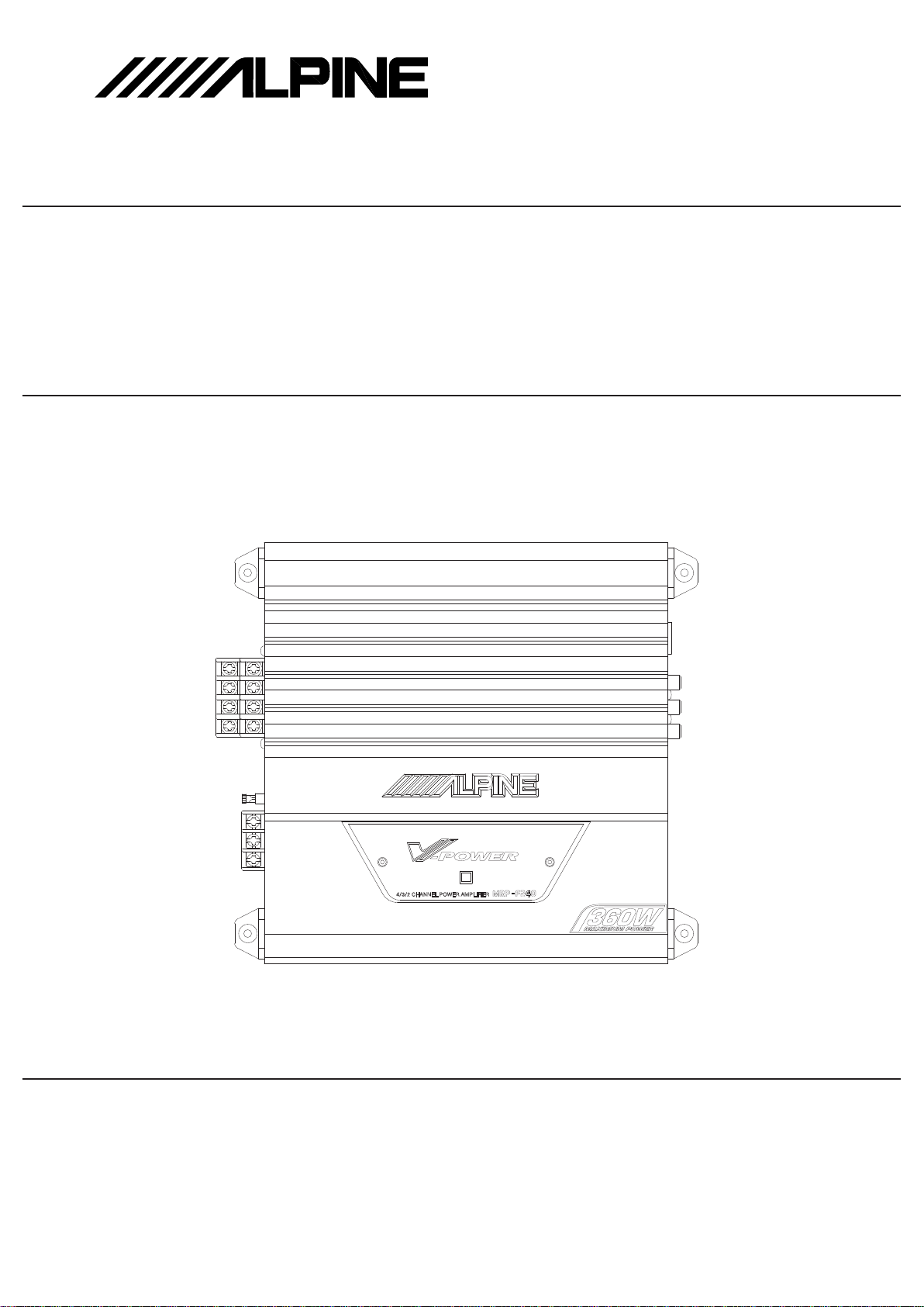
MRP-F240
SERVICE MANUAL
4/3/2 CHANNEL POWER AMPLIFIER
1/03-A
68E35050S01
TO ALPINE Home Page
Page 2
<Cautions for Safe Repair Work>
r
s
The following cautions will prevent accidents in the workplace and will ensure safe products.
*The symbols indicate caution is needed to prevent injuries and damage to property.
The symbols and their meanings follow.
Warning
Caution
*The following symbols indicate two levels of cautions.
When you see this symbol, you have to be very careful.
When you see this symbol, you have to follow the instructions there.
If you ignore this symbol and handle the product incorrectly or unsafely,
serious injury or death may result.
If you ignore this symbol and handle the product incorrectly or unsafely,
injury or only material damage may result.
Warning
Do not look squarely into the laser light
coming from the pickup. Always use a designated fuse.
You may loose you sight. Use of an incorrect fuse may result in a fire.
Caution
Do not allow wiring to be caught in the Battery Caution
screw/chassis. Use the designated battery.
If wiring is caught in the screw/chassis, it may Confirm the correct polarity and seat of the
cause a short circuit, resulting in a fire. battery.
Fuse Caution
An incorrect battery or an improperly connected
or seated battery may result in a fire.
High Temperature Caution Designated Parts Caution
Touching the heat sink may cause severe burns. Look up the part list and ensure that only
designated parts are used to prevent problems or
accidents.
Reverse Power Supply Connections o
Misconnections Caution Ensure that the wiring is correct when rewiring to
Reverse power supply connections or prevent problems with ignition/breakdown.
misconnections may cause ignition problems and
smoke may result.
Soldering Caution Wear Glove
Hot solder from solder splash may cause severe Wear gloves to prevent electrical shocks or injury
burns. from the end face of the metal.
Wiring Caution
Page 3

Contents
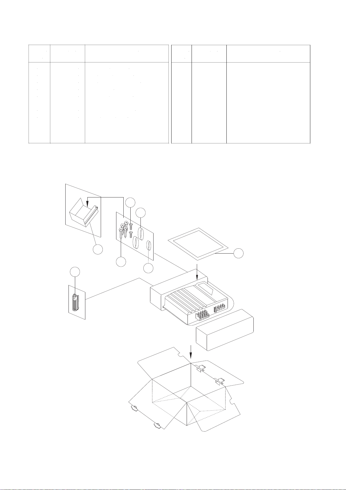
Packing Assembly Parts List
Packing Method View
Specifications
Block Diagram
Parts Layout on P.W.Boards and Wiring Diagram
Schematic Diagram
Terminal Voltage of IC/TR
Exploded View (Cabinet)
NOTE : Due to continuing product improvement, specifications and designs are subject to
change without notice.
Page 4
R
104
103
106
101
102
105
X4
X2
X2
107
Symbol
No.
Part No.
Description
101
102
103
104
105
106
107
68P02294K68
03E34961S01
03E34955S01
15E34956S01
75E22439S01
75E22440S01
01E23875S01
OWNER'S MANUAL
SCR M4X20 TPG1,BLK
SCR M3X10(B)MCH(BLK)
COVER,RCA
HOUSING RUBBER-B
HOUSING,RUBBER(C)
ASS'Y INPUT WIRE
Packing Method View
Symbol
No.
Part No.
Description
Packing Assembly Parts List
TO CONTENTS
Page 5

Specifications
T.H.D. (DC14.4V, 20Hz~20kHz) ....................................................................... 4ohm-Load/4ch, 35W Output : 0.2%
4ohm-Load/2ch (BTL), 95W Output : 1.0%
Power Output (Normal Input, DC14.4V, 20Hz~20kHz) ..................................... 0.2% T.H.D., 4ohm-Load/4ch : 35W
1.0% T.H.D., 4ohm-Load/2ch (BTL) : 90W
S/N Ratio (Ref. Output 35W/4ohm, Input Shorted) ............................................................................................ 94dB
Input Sensitivity (35W Output) .................................................................... GAIN-VR Center : RCA Input : 1.1V±5dB
SP Input : 2.2V±5dB
GAIN-VR CW : RCA Input : 0.2V±5dB
SP Input : 0.4V±5dB
GAIN-VR CCW : RCA Input : 4.5V±5dB
SP Input : 8.9V±5dB
Frequency Response Ratio (Ref. 1kHz, 0±1dB) ..................................................................................... 20Hz~40kHz
Current Drain ..................................................................................................................................... No Signal : 1.5A
4ohm-Load/4ch, T.H.D. 10% : 30A
Residual Noise (Input Shorted, 4ohm-Load/4ch, VR Center) ........................................................................... 3.0mV
Channel Separation (Input Shorted, 1kHz, 35W Output) .................................................................................... 55dB
Remote on Voltage (1W Output) .......................................................................................................... 6.5+1.0, -1.5V
Remote Current Drain ....................................................................................................................................... 3.0mA
Back-up Current Drain ...................................................................................................................................... 1.2mA
Input Impedance
............................................................................................................... RCA Input : 13.8±2.0kohm
SP Input : 13.8±2.0kohm
Power Source ........................................................................................................................... DC14.4V (9.0~16.0V)
Dimensions (W x H x D)
........................................................................................................... 265.6 x 60 x 241.4mm
Weight ............................................................................................................................................................... 2.54kg
NOTE : Due to Continuing product improvement, specifications and designs are subject to change without notice.
TO CONTENTS
Page 6
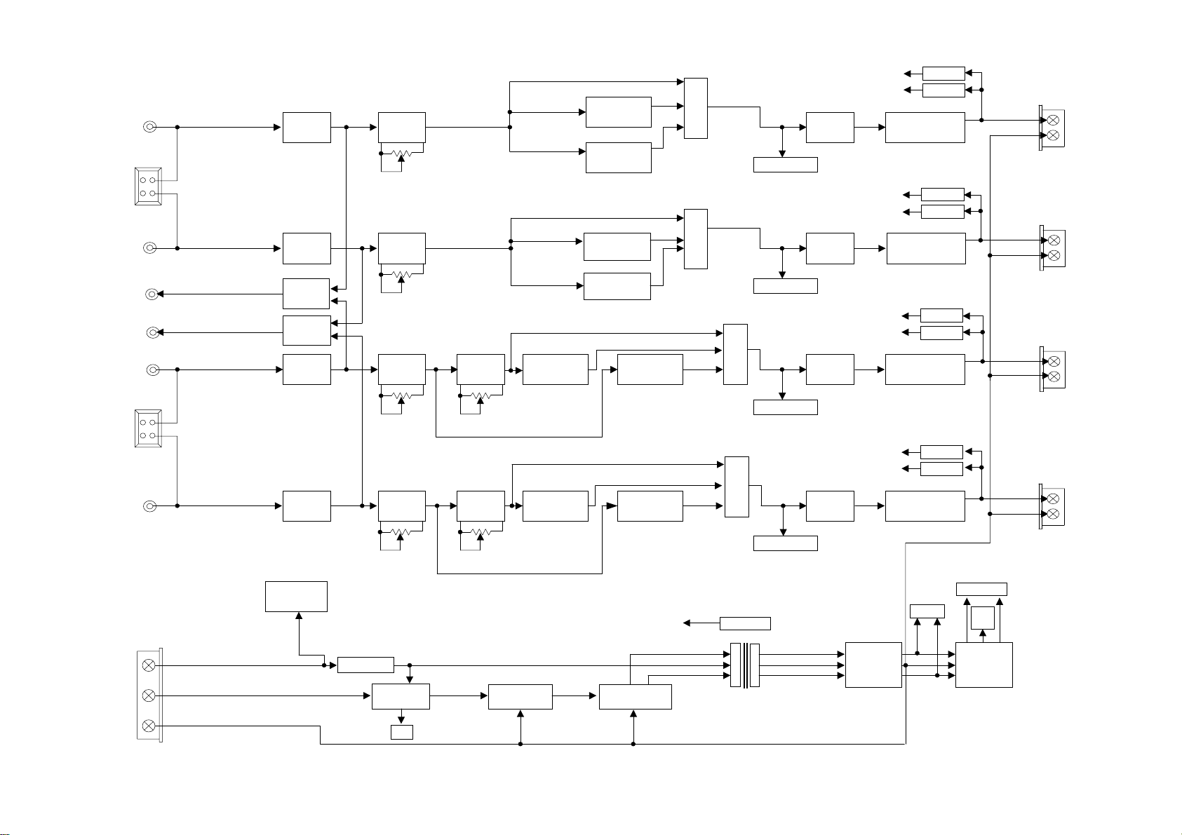
Block Diagram
TO CONTENTS
HPF(12dB/OCT)
RCA-IN CH-1(+)
CH-1(L) CH-1(-)
ISOLATOR GAIN
SP-IN
CH-1 50K-A
CH-2
RCA-IN CH-2(-)
CH-2(R) CH-2(+)
PRE-OUT
CH-1+3(L) 50K-A
ISOLATOR GAIN
BUFFER
80Hz-FIX
LPF(12dB/OCT)
80Hz-FIX
HPF(12dB/OCT)
80Hz-FIX
LPF(12dB/OCT)
80Hz-FIX
PRE-OUT
CH-2+4(R)
RCA-IN CH-3(+)
CH-3(L) CH-3(-)
BUFFER
ISOLATOR GAIN
BASS EQ
LPF(12dB/OCT)
80Hz-FIX
HPF(12dB/OCT)
80Hz-FIX
SEL
S/W
MUTE ON/OFF
SEL
S/W
MUTE ON/OFF
SEL
S/W
DC off set
Over Current Protect
Pre
drive
DC off set
Over Current Protect
Pre
drive
DC off set
Over Current Protect
Pre
drive
SENSOR
SENSOR
POWER AMP
SENSOR
SENSOR
POWER AMP
SENSOR
SENSOR
POWER AMP
SEL
S/W
Thermal
Power trans
MUTE ON/OFF
MUTE ON/OFF
DC off set
Over Current Protect
Pre
drive
RECTIFIER
AND
REGULATER
SENSOR
SENSOR
POWER AMP
±Vcc
±15V
GND
SIG
±15V
REGULATOR
SP-IN
CH-3 50K-A 5K-E
CH-4
RCA-IN CH-4(-)
CH-4(R) CH-4(+)
BATT
REM
GND
ISOLATOR GAIN
MUTE ON/OFF
DRIVER
LINE CHOKE
BASS EQ
50K-A 5K-E
POWER
ON/OFF
LED
LPF(12dB/OCT)
80Hz-FIX
PWM IC
HPF(12dB/OCT)
80Hz-FIX
Over Temperature Protect (Trans)
POWER
FET
Page 7

Q525
TO CONTENTS
TO PARTS LIST
TO P. W. Board
47
47
R537
R545
Q529
KTA1266
C509
5p
R553
R549
110
R541
220/10
7.5k
R561
B2K-1/8
0.01
C513
3.3K
R565
18p
C517
1.2K
16k
R557
R569
180-1/8
KTC3228
Q533
KSC2682
R573
180-1/8
C525
C521
Q537
2.2/50
68p
R725
10K-1/8
E521
68p
Q545
R577
2SC2412K
180-1/4
Q541
KTA1275
R589 R597
Q553
KTB688
Q549
KTD718
1K-1/8
R593
R717
0.1-3Wx2
1.5k
10-1W
R721
12K
C529
0.047
R105
E101
11K
22kR101
RCA101-1
R109
11K-1/8
R117
10/25
1K
R113 22K
E105
10/25
R121
1.2K
C105 100p
100p
C109
C101
RCA JACK 06P
IC101
NJM4560M
R125 120K
R134
15k-F
R138
15K-F
C117 10p
R146 15K-F
C113
10p
R142
15k-F
120K
R130
1000p
R213
910-1/B
VR201-1
50KA
C205
10p
C121
1000p
R201
6.8k-1/8
IC105
NJM4560M
1.5k
R209
C122
1000p
6.8k
R205
C201
C301
0.033
R309
R305
120k
120k
8200p
51k
R301
33p
R313
910
IC201
NJM4560M
C317
C321
0.018
E301
2.2/50
C305
220k
R321
0.018
R317
47k
E305
0.22/50
E501
R501
22/50
9.1k
SW301-1
SSAF 123NA
27k
R325
E505
R509
22/50
1.2K
R513
5.6K-1/8
Q501
KTC2874-B
4.3k
R505
C501 560p
47
R521
Q517
2SA1037K
Q505
2SA1037K
C505
R529
1000p
470
Q521
2SC2412K
Q509
2SC2412K
Q513
2SC2412K
R533
0.47/50
R517 12K
E509
240
KTC3198
D501
330
R525
1SS133
D505
1SS133
E513
0.47/50
E517
RCA101-5
RCA JACK 06P
RCA101-6
RCA JACK 06P
SP101
CONN BASE 5569-08AI
R150
R159 47k
220
47k
R151
R160
1k
E110
22/50
E111
22/50
2K-1/8
R155
22k R103
C103
47
R522
Q518
2SA1037k
Q506
2SA1037k
R530
C506
470
1000p
Q522
2SC2412k
Q510
2SC2412k
Q514
2SC2412k
R534
240
KTC3198
D502
330
R526
R518 12k
E510 0.47/50
R511
1.2k
R515
5.6k
1SS133
D506
1SS133
E514
0.47/50
47
Q519
ER523
2SA1037K
Q507
2SA1037K
R531
470
Q511
2SC2412K
E511
0.47/50
330
R527
R519 12k
D503
E515
560p
C503
0.47/50
120kR126
R156 2K
R157
2K
120K
120K
R135
C118
10p
15k-F
R139
15K-F
C114 10p
R143
NJM4560M
R136
15K-F
R140
15K-F
C119 10p
R148 15K-F
IC102
NJM4560M
15K-F
IC103
C115
10p
R144
15k-F
R147
15K-F
R203
6.8k-1/8
IC107
NJM4560M
R214
910
VR201-2
50KA
C206
10p
R202
6.8K-1/8
IC106
NJM4560M
6.8k
R206
R215
910-1/8
VR202-1
50KA
C207
10p
33pC203
1.5k
R211
6.8K
R207
R306
120k-1/8
51k
1.5k
R302
R210
33p
C202
C302
0.033
R310
120k
R314
910-1/8
C306
R331
5.1k
R335
E311
2.2/50
R337
1.5k
C325
0.022
150k
R333
8200p
5.1k
E302
2.2/50
5KE
VR302-1
IC205
NJM4560M
IC202
NJM4560M
E502
22/50
R326
R315
910
IC203
NJM4560M
C323
0.018
27k
R319 47k
SW301-2
SSAF 123NA
C319
0.018
C318
C322
0.018
0.018
220k
R322
E309
0.33/50
R339
5.1k
C327
10p
R318
47k
E306
0.22/50
C303
0.033
R311
R307
120k
120k
51k
R303
C307
8200p
220k
R323
R502
E506
R510
22/50
9.1k
4.3k
R506
E307
0.22/50
R327
E303
2.2/50
Q502
KTC2874-B
E503
22/50
SW302-1
SSAF 123NA
27k
R503
1.2k
R514
5.6k
C502 560p
9.1k
E507
22/50
Q503
KTC2874-B
4.3k
R507
R812
10k
R810
100k
47k
R811
R106
E102
RCA JACK 06P
IC109
NJM4560M
10p
10/25
E107
10/25
10/25
E106
10/25
E103
R118
1K-1/8
22k
100p
R114
C106
120K
100p
C110
R122
R131
1.2K
C102
1000p
R154
10K-1/8
11K
R152
R119
11K
N.U.
R127
100p
C107
100p
C111
R153
R132
R115 22K
R123
1.2K
11k
22kR102
RCA101-2
R110
11k
C129
R107
11K
RCA101-3
RCA JACK 06P
R111
11k
1000p
R53847R546
Q526
R542
E518 220/10
R539
C507
1000p
Q515
2SC2412K
R535
240
Q527
KTC3198
1SS133
D507
1SS133
E519
220/10
C510
5p
110
47
2SC2412K
Q523
R543
47
Q530
KTA1266
7.5k
R562
R554
82k-1/8
0.01
C514
3.3k
R566
18p
C518
16k
R558
1.2k R550
47
R547
Q531
KTA1266
C511
5p
R555
82k-1/8
7.5k
R563
0.01
C515
3.3k
R567
110
C519
R559 16k
R551 1.2k
68p
C522
R570
180-1/8
Q538
KTC3228
Q534
KSC2682
E522
2.2/50
R578
R574
180-1/8
68p
C526
R571
R523
180-1/8
Q539
KTC3228
E523
2.2/50
R579
180-1/4
Q535
KSC2682
Q543
KTA1275
R575
180-1/8
C527
18p
Q542
KTA1275
68p
68p
R726
Q546
2SC2412k
180-1/4
Q555
KTB688
10k-1/8
Q547
2SC2412k
R591
R598
R590
KTB688
1.5k
Q554
1k-1/B
1.5k
Q550
KTD718
Q551
KTD718
R727
R594
R718
0.1-3Wx2
C530
10-1W
0.047
R722
12k
BLT902
BLOCK TERMINAL 8P
10k-1/8
R719
C531
10-1W
R599
1k-1/B
R595
0.1-3Wx2
R723
0.047
12k
R158
2k-1/8
E104
10/25
10/25
E108
R120
1k
100p
C108
R116 22k
100p
C112
R124
1.2k
C104
R108
11k
RCA101-4
RCA JACK 06P
R104 22k
R112
11k
IC104
NJM4560M
C116
10p
R145
120k
R129
R133
1000p
120k
R137
15k-F
R141
15k-F
C120 10p
R149 15k-F
15k-F
R204
6.8k-1/8
IC108
NJM4560M
C124 1000p
R216
910
C208
10p
VR202-2
50KA
R208
2SA1037K
Q508
2SA1037K
R532
470
Q512
2SC2412K
2SC2412K
330
D504
1SS133
Q520
Q516
C508
1000p
R536
240
E520
220/10
KTC3198
D508
1SS133
Q528
R540
47
2SC2412K
R544
Q524
C512
47
R548
5p
R556 82k-1/8
110
R560 16k
R552 1.2k
Q532
KTA1266
C516
R572
68p
C524
180-1/8
Q540
KTC3228
E524
2.2/50
R580
Q536
KSC2682
R576
180-1/8
Q544
KTA1275
C528
180-1/4
68p
Q556
KTB688
7.5k
R564
0.01
3.3k
R568
18p
C520
Q548
2SC2412K
1.5k
R592
Q552
KTD718
R728
10k-1/8
R720
C532
10-1W
R600
1k-1/B
0.047
R724
R596
0.1-3Wx2
12k
47
R332
5.1K
R336
5.1K-1/8
5KE
VR302-2
E312
2.2/50
R338
1.5k
C326
0.022
IC206
NJM4560M
1.5k
R212
C204 33p
6.8-k
C123 1000p
150k
R334
C328
R340
10p
0.33/50
5.1k
E310
C304
0.033
R312
R308
120k
120k-1/8
51k
R304
C308
R316
910-1/8
IC204
NJM4560M
R320 47k
C324
C320
0.018
8200p
220k
R324
0.018
E504
R504
22/50
9.1k-1/8
SW302-2
SSAF 123NA
E308
0.22/50
27k
R328
E304
2.2/50
R512
1.2k
E508
22/50
R516
5.6k
Q504
KTC2874-B
4.3k
R508
R524
E512
0.47/50
R528
R520 12k
560p
C504
E516
0.47/50
Page 8

BLT901
TO CONTENTS
TO PARTS LIST
TO P. W. Board
FUSE TERMINAL 3P
F901
FUSE, AUTO 25A
D901
1N4004
R901
R902
T901
CHOKE TRANS
R903
Q902
10k
DTC143EK
C901 0.15
10k
CONN BASE, GIL-S-02P-S2T2
2P CONNECTOR ASSY
Q605
KSC2690A
T601
ASS'Y POWER TRANS
R605
10-1/8
Q601
R606
10-1/8
R603
110-1/2
R607
10-1/8
R604
110-1/2
R608
10-1/B
Q802
Q901
KTA1275
150k
3.3k
R904
R905
2.7k-1/4
R907
5.6k-1/4
CONN901
CON901
LED901
YLB-304W,3
D803
1SS133
D804
1SS133
R801
D801
1N4004
12k
D802
1SS133
ZD801
Q801
2SA1037K
R802
100k
2k
R805
4.7k
R803
D805
1N4004
E802
E801
MTZ-J-6.8-A
10/25
220/10
100k
R804
DTA144EK
R806
100k
Q803
DTC144EK
R809
680k
Q804
2k
R807
2SC2412K
1M
R808
E803
10/25
IRFZ44N
Q602
IRFZ44N
Q603
IRFZ44N
Q604
IRFZ44N
R701
1k
E701
100/10 (B.P)
1k
R702
E603
3300/16
E604
3300/16
1k
R703
Q701
2SC2412K
Q702
2SC2412K
R609
10-1W
C602
0.022
C603
0.022
R610
10-1W
Q703
2SA1037K
D601
R613
10-1W
F10P20F
C604
E607
C606
1000p
C607
1000p
R614
10-1W
E702
2.2/50
R704
3.3k
Q704
2SA1037K
470
R716
R732
4.7k
E703
100/25
D602
F10P20FR
R707
100k
R705
E608
1k
0.047
2200/35
C605
0.047
2200/35
R714
240k
E704
Q707
2SC2412K
R730
220/10
Q706
2SA1037K
R715
510k
47k
62k
R729
10k
R712
20k
TH701
ZD701 MTZ-J-22-B
R710 22k
R706 20k
R711 20k
150
R709
5.6k
R708
R713
10k
Q705
2SC2412K
R611
2.7k-1/4
E611
Q606
47/25
MTZ-J-16-B
MTZ-J-16-B
E612
47/25
E601
10/25
IC601 uPC494GS
R601 8.2k
C601 1500p
R602 18k
E602
10/25
E609
ZD601
0.47/50
E610
ZD602
0.47/50
R612
2.7k-1/4
KSA1220A
D701
1SS133
D702
1SS133
2k
R731
E705
10/25
Page 9

Terminal Voltage of IC/TR
TO CONTENTS
TO SCHEMATIC
IC101 IC102 IC103
1 5.7m 1 5.7m 1 5.4m 1 5.7m
2 5.7m 2 5.7m 2 5.4m 2 5.7m
3 5.4m 3 5.4m 3 5.5m 3 5.3m
4 -15.5 4 -15.5 4 -15.3 4 -15.3
5 5.4m 5 5.4m 5 5.4m 5 5.3m
6 6.0m 6 6.0m 6 5.6m 6 6.0m
7 6.0m 7 6.0m 7 5.6m 7 6.0m
8 15.3 8 15.3 8 15.2 8 15.2
IC105 IC106 IC107 IC108
1 0.0 1 0.0 1 0.0 1 0.0
2 4.0m 2 3.3m 2 3.5m 2 3.8m
3 3.3m 3 5.2m 3 3.1m 3 3.2m
4 -15.5 4 -15.5 4 -15.5 4 -15.5
5 0.0 5 0.0 5 0.0 5 0.0
6 0.0 6 0.0 6 0.0 6 0.0
7 10.8m 7 0.0 7 11.0m 7 4.0m
8 15.3 8 15.3 8 15.3 8 15.3
IC109 IC201
1 0.0 1 22.6m 1 11.3m 1 13.1m
2 0.0 2 22.6m 2 11.3m 2 13.5m
3 0.0 3 22.4m 3 11.3m 3 14.3m
4 -15.4 4 -15.5 4 -15.5 4 -15.5
5 2.1m 5 10.4m 5 10m 5 9.2m
6 2.1m 6 11.0m 6 10.3m 6 10.6m
7 0.0 7 11.0m 7 10.3m 7 10.6m
8 15.4 8 15.4 8 15.4 8 15.4
IC202
IC104
IC203
IC204 IC205
1 13.5m 1 6.8m 1 7.2m
2 13.5m 2 6.8m 2 7.2m
3 13.2m 3 6.8m 3 6.9m
4 -15.5 4 -15.5 4 -15.5
5 10m 5 11.4m 5 4.5m
6 10.5m 6 12.0m 6 5.4m
7 10.5m 7 12.0m 7 5.4m
8 15.3 8 15.3 8 15.3
IC601
1 0.0 9 5.15
2 4.97 10 5.65
3 83m 11 14.3
4 0.18 12 14.3
5 1.73 13 4.97
6 3.7 14 4.97
7 0.0 15 4.97
8 14.3 16 0.0
IC206
Page 10

Ref. No. E C B Ref. No. E C B
TO CONTENTS
TO SCHEMATIC
Q501 0.0 0.0 -2.74 Q541 -0.5 -26.0 -1.1
Q502 0.0 0.0 -2.75 Q542 -0.5 -26.0 -1.1
Q503 0.0 0.0 -2.75 Q543 -0.5 -26.0 -1.1
Q504 0.0 0.0 -2.75 Q544 -0.51 -26.0 -1.1
Q505 25.4 24.6 24.8 Q545 18.2m 25.4 19.5m
Q506 25.4 24.6 24.8 Q546 23.2m 25.4 23.5m
Q507 25.4 24.6 24.8 Q547 18.8m 25.4 18.5m
Q508 25.4 24.6 24.8 Q548 18.1m 25.4 18.4m
Q509 -0.66 24.6 -47.6m Q549 19.6m 25.4 0.54
Q510 -0.65 24.6 -45.4m Q550 23.5m 25.4 0.55
Q511 -0.65 24.6 -46.8m Q551 18.9m 25.4 0.55
Q512 -0.65 24.6 -47.4m Q552 18.5m 25.4 0.55
Q513 -25.5 -0.64 -24.9 Q553 19.3m -26.1 -0.5
Q514 -25.5 -0.64 -24.9 Q554 22.8m -26.1 -0.5
Q515 -25.5 -0.64 -24.9 Q555 18.4m -26.1 -0.5
Q516 -25.5 -0.64 -24.9 Q556 17.5m -26.1 -0.51
Q517 25.4 24.8 24.8 Q605 15.5 25.44 16.0
Q518 25.4 24.8 24.8 Q606 -15.6 -26.0 -16.2
Q519 25.4 24.8 24.8 Q701 0.0 25.4 4.13m
Q520 25.4 24.8 24.8 Q702 3.8m 25.4 0.0
Q521 -0.66 24.8 -44.0m Q703 25.4 0.0 25.4
Q522 -0.65 24.8 -40.6m Q704 25.4 25.0m 25.4
Q523 -0.65 24.8 -43.5m Q705 0.0 4.97 17.2m
Q524 -0.65 24.8 -47.8m Q706 4.97 -62.0m 4.97
Q525 -25.6 -1.09 -24.9 Q707 25.4 14.9m 25.4
Q526 -25.6 -1.09 -24.9 Q801 6.59 8.7m 6.59
Q527 -25.6 -1.09 -24.9 Q802 14.4 -2.75 14.4
Q528 -25.6 -1.1 -24.9 Q803 4.4m 14.4 8.5m
Q529 25.2 1.09 24.6 Q804 0.0 3.7m 0.56
Q530 25.2 1.1 24.6 Q901 14.4 14.4 13.7
Q531 25.2 1.1 24.6 Q902 0.0 23.2m 3.67
Q532 25.2 1.1 24.6
Q533 -1.1 1.1 -0.45
Q534 -1.1 1.11 -0.45 Ref. No. G D S
Q535 -1.1 1.1 -0.45 Q601 5.64 14.4 2.33m
Q536 -1.1 1.11 -0.46 Q602 5.64 14.4 2.45m
Q537 0.55 25.4 1.11 Q603 5.65 14.4 1.67m
Q538 0.56 25.4 1.12 Q604 5.65 14.4 2.0m
Q539 0.55 25.4 1.11
Q540 0.56 25.4 1.12
[Measuring Conditions]
1. Power Supply Voltage : DC14.4V
2. Measuring Meter : Digital Multi Meter
3. Measuring Point Reference : Between GND
4. Measuring Conditions : No Signal Input
Page 11

Exploded View (Cabinet)
TO CONTENTS
TO PARTS LIST
12 X6
SP101
17
22 X3
10 X12
18 X2
23
19
21
RCA101
17
K
29
17
28 X2
9
30
10 X4
27
Q
16
L
E
18 X2
16
21
23
20 X2
D
19
L
F
M
K
Q
10 X2
F901
27
17
Q
J
20 X2
BLT901
28 X4
11
A
5
M
BLT902
16 X2
8
17 X2
D
C
8
B
6
E
22 X3
4
L
M
2
L
M
15 X2
A
N
13
14
P
C
G
F
1
26
24 X2
N
P
B
G
H
25
G
H
21
J
19
H
18 X2
3
H
G
23
21
19
23
20 X3
Page 12

MRP-F240
Cabinet Assembly Parts List
Note : The part that has not PART NUMBER will not be
supplied.
1- - - - - - - - - - MAIN HEAT SINK
2- - - - - - - - - - CHAS,FRONT
3- - - - - - - - - - CHAS,REAR
4- - - - - - - - - - COVER BOTTOM
5- - - - - - - - - - SUB,HEAT SINK(RL)
6- - - - - - - - - - SUB HEAT SINK(D)
814E11487S01 INSULATOR,SHEET-B
914E20977S01 INSULATOR,SHEET-A
1003E20922S01 SCR M3X11(S.W)TPG-TPT(YEL)
1107E11146S01 BKT,TR
1203E29347S01 SCR M3X11(W)TPG-TPT(YEL)
1315E34943S01 HOLDER,LED
1461E34941S01 LENS,LED
1503E24424S01 SCR M2.6X5(B)TPG-TPT(YEL)
1603E09417S10 SCR M3X10(B)TPG-TPT(YEL)
1703E34940S01 SCR M3X14(SW)TPG-TPT(YEL)
1803E20077S01 SCR M3X6(B)TPG-TPT(BLK)
1929E34942S01 LEG,MTG
2003E09416S10 SCR M3X8(P)TPG-TPT(BLK)
2103E34938S01 SCR M3X11(B)MCH-TPT(BLK)
2203E22133S01 SCR M2.6X6(B)MCH-TPT(BLK)
2303E20919S01 SCR M3X8(B)TPG-TPT(BLK)
2403E34939S01 WRENCH BOLT M2.6X11(WHT)
25- - - - - - - - - - BADGE,PLATE
26- - - - - - - - - - BADGE,V-POWER
2729E23793S01 LUG,GND
28- - - - - - - - - - SUPPORT PWB
2907E27744S01 BKT,GND-(A)
3007E27745S01 BKT,GND-(B)
Page 13

MRP-F240
Electrical Parts List
*******MAIN P.W.Board
=======IC's
IC101 51E22130S01 IC, NJM 4560M-TE3
IC102 51E22130S01 IC, NJM 4560M-TE3
IC103 51E22130S01 IC, NJM 4560M-TE3
IC104 51E22130S01 IC, NJM 4560M-TE3
IC105 51E22130S01 IC, NJM 4560M-TE3
IC106 51E22130S01 IC, NJM 4560M-TE3
IC107 51E22130S01 IC, NJM 4560M-TE3
IC108 51E22130S01 IC, NJM 4560M-TE3
IC109 51E22130S01 IC, NJM 4560M-TE3
IC201 51E22130S01 IC, NJM 4560M-TE3
IC202 51E22130S01 IC, NJM 4560M-TE3
IC203 51E22130S01 IC, NJM 4560M-TE3
IC204 51E22130S01 IC, NJM 4560M-TE3
IC205 51E22130S01 IC, NJM 4560M-TE3
IC206 51E22130S01 IC, NJM 4560M-TE3
IC601 51E27890S01 IC,uPC 494GS
=======Transistors/FET's
Q501 48E31104S01 TR,KTC2874-B-RD
Q502 48E31104S01 TR,KTC2874-B-RD
Q503 48E31104S01 TR,KTC2874-B-RD
Q504 48E31104S01 TR,KTC2874-B-RD
Q505 48E22900S01 TR,2SA1037K-CP
Q506 48E22900S01 TR,2SA1037K-CP
Q507 48E22900S01 TR,2SA1037K-CP
Q508 48E22900S01 TR,2SA1037K-CP
Q509 48E22902S01 TR,2SC2412K-T146-CP
Q510 48E22902S01 TR,2SC2412K-T146-CP
Q511 48E22902S01 TR,2SC2412K-T146-CP
Q512 48E22902S01 TR,2SC2412K-T146-CP
Q513 48E22902S01 TR,2SC2412K-T146-CP
Q514 48E22902S01 TR,2SC2412K-T146-CP
Q515 48E22902S01 TR,2SC2412K-T146-CP
Q516 48E22902S01 TR,2SC2412K-T146-CP
Q517 48E22900S01 TR,2SA1037K-CP
Q518 48E22900S01 TR,2SA1037K-CP
Q519 48E22900S01 TR,2SA1037K-CP
Q520 48E22900S01 TR,2SA1037K-CP
Q521 48E22902S01 TR,2SC2412K-T146-CP
Q522 48E22902S01 TR,2SC2412K-T146-CP
Q523 48E22902S01 TR,2SC2412K-T146-CP
Q524 48E22902S01 TR,2SC2412K-T146-CP
Q525 48E09088S01 TR,KTC 3198-Y-RD
Q526 48E09088S01 TR,KTC 3198-Y-RD
Q527 48E09088S01 TR,KTC 3198-Y-RD
Q528 48E09088S01 TR,KTC 3198-Y-RD
Q529 48E09036S02 TR,KTA 1266-Y-RD
Q530 48E09036S02 TR,KTA 1266-Y-RD
Q531 48E09036S02 TR,KTA 1266-Y-RD
Q532 48E09036S02 TR,KTA 1266-Y-RD
Q533 48E08329S01 TR,KSC 2682-Y
Q534 48E08329S01 TR,KSC 2682-Y
Q535 48E08329S01 TR,KSC 2682-Y
Q536 48E08329S01 TR,KSC 2682-Y
Q537 48E23701S01 TR KTC 3228-0-RD
Q538 48E23701S01 TR KTC 3228-0-RD
Q539 48E23701S01 TR KTC 3228-0-RD
Q540 48E23701S01 TR KTC 3228-0-RD
Q541 48E23700S01 TR KTA 1275-0-RD
Q542 48E23700S01 TR KTA 1275-0-RD
Q543 48E23700S01 TR KTA 1275-0-RD
Q544 48E23700S01 TR KTA 1275-0-RD
Q545 48E22902S01 TR,2SC2412K-T146-CP
Q546 48E22902S01 TR,2SC2412K-T146-CP
Q547 48E22902S01 TR,2SC2412K-T146-CP
Q548 48E22902S01 TR,2SC2412K-T146-CP
Q549 48E27748S01 TR,KTD 718-O
Q550 48E27748S01 TR,KTD 718-O
Q551 48E27748S01 TR,KTD 718-O
Q552 48E27748S01 TR,KTD 718-O
Q553 48E27747S01 TR,KTB 688-O
Q554 48E27747S01 TR,KTB 688-O
Q555 48E27747S01 TR,KTB 688-O
Q556 48E27747S01 TR,KTB 688-O
Q601 48E29536S01 FET,IRFZ 44N
Q602 48E29536S01 FET,IRFZ 44N
Q603 48E29536S01 FET,IRFZ 44N
Q604 48E29536S01 FET,IRFZ 44N
Q605 48E10027S01 TR,KSC 2690A-Y
Q606 48E05943S01 TR,KSA 1220A-Y
Q701 48E22902S01 TR,2SC2412K-T146-CP
Q702 48E22902S01 TR,2SC2412K-T146-CP
Q703 48E22900S01 TR,2SA1037K-CP
Q704 48E22900S01 TR,2SA1037K-CP
Q705 48E22902S01 TR,2SC2412K-T146-CP
Q706 48E22900S01 TR,2SA1037K-CP
Q707 48E22902S01 TR,2SC2412K-T146-CP
Q801 48E22900S01 TR,2SA1037K-CP
Q802 48E23697S01 TR,DTA 144EK-T146-CP
Q803 48E22555S01 TR,DTC 144EK-T146-CP
Q804 48E22902S01 TR,2SC2412K-T146-CP
Q901 48E23700S01 TR KTA 1275-0-RD
Q902 48E22903S01 TR,DTC 143EK-T-146-CP
=======Diodes
D501 48E22916S01 DIO,1SS133-T-77-AX
D502 48E22916S01 DIO,1SS133-T-77-AX
D503 48E22916S01 DIO,1SS133-T-77-AX
D504 48E22916S01 DIO,1SS133-T-77-AX
D505 48E22916S01 DIO,1SS133-T-77-AX
D506 48E22916S01 DIO,1SS133-T-77-AX
D507 48E22916S01 DIO,1SS133-T-77-AX
D508 48E22916S01 DIO,1SS133-T-77-AX
D601 48T65059W01 DIO,REC F10P20F
D602 48T65059W02 DIO,REC F10P20FR
D701 48E22916S01 DIO,1SS133-T-77-AX
D702 48E22916S01 DIO,1SS133-T-77-AX
D801 48E33671S01 DIO,1N 4004-AX
D802 48E22916S01 DIO,1SS133-T-77-AX
D803 48E22916S01 DIO,1SS133-T-77-AX
D804 48E22916S01 DIO,1SS133-T-77-AX
D805 48E33671S01 DIO,1N 4004-AX
Page 14

MRP-F240
D901 48E33671S01 DIO,1N 4004-AX
ZD601 48E22436S01 DIO,ZEN,MTZ-J-16-B-AX
ZD602 48E22436S01 DIO,ZEN,MTZ-J-16-B-AX
ZD701 48E08332S01 DIO,ZEN,MTZ-J-22-B-AX
ZD801 48E22917S01 DIO,ZEN,MTZ-J-6.8-A-AX
=======Switches
SW301 40E20895S01 S/W SSAF 123NA((80Hz)
FILTER)
SW302 40E20895S01 S/W SSAF 123NA((80Hz)
FILTER)
=======Coil
T901 24E29250S01 CHOKE TRANS 28MM 150
=======Thermistor
TH701 48E20887S01 TH,YTD5-320(20K)-YEL
=======Transformer
T601 25E29258S01 ASS'Y POWER TRANS
=======Capacitors
C101 08E28769S01 CAP,CER 102-K-SL1H -CP
C102 08E28769S01 CAP,CER 102-K-SL1H -CP
C103 08E28769S01 CAP,CER 102-K-SL1H -CP
C104 08E28769S01 CAP,CER 102-K-SL1H -CP
C105 08E28764S01 CAP,CER 101-J-SL1H-CP
C106 08E28764S01 CAP,CER 101-J-SL1H-CP
C107 08E28764S01 CAP,CER 101-J-SL1H-CP
C108 08E28764S01 CAP,CER 101-J-SL1H-CP
C109 08E28764S01 CAP,CER 101-J-SL1H-CP
C110 08E28764S01 CAP,CER 101-J-SL1H-CP
C111 08E28764S01 CAP,CER 101-J-SL1H-CP
C112 08E28764S01 CAP,CER 101-J-SL1H-CP
C113 08E28760S01 CAP,CER 10R-D-SL1H-CP
C114 08E28760S01 CAP,CER 10R-D-SL1H-CP
C115 08E28760S01 CAP,CER 10R-D-SL1H-CP
C116 08E28760S01 CAP,CER 10R-D-SL1H-CP
C117 08E28760S01 CAP,CER 10R-D-SL1H-CP
C118 08E28760S01 CAP,CER 10R-D-SL1H-CP
C119 08E28760S01 CAP,CER 10R-D-SL1H-CP
C120 08E28760S01 CAP,CER 10R-D-SL1H-CP
C121 08E28769S01 CAP,CER 102-K-SL1H -CP
C122 08E28769S01 CAP,CER 102-K-SL1H -CP
C123 08E28769S01 CAP,CER 102-K-SL1H -CP
C124 08E28769S01 CAP,CER 102-K-SL1H -CP
C129 08E28760S01 CAP,CER 10R-D-SL1H-CP
C201 08E28762S01 CAP,CER 33R-J-SL1H-CP
C202 08E28762S01 CAP,CER 33R-J-SL1H-CP
C203 08E28762S01 CAP,CER 33R-J-SL1H-CP
C204 08E28762S01 CAP,CER 33R-J-SL1H-CP
C205 08E28760S01 CAP,CER 10R-D-SL1H-CP
C206 08E28760S01 CAP,CER 10R-D-SL1H-CP
C207 08E28760S01 CAP,CER 10R-D-SL1H-CP
C208 08E28760S01 CAP,CER 10R-D-SL1H-CP
C301 08E33406S01 CAP,MYL,333-J-RD
C302 08E33406S01 CAP,MYL,333-J-RD
C303 08E33406S01 CAP,MYL,333-J-RD
C304 08E33406S01 CAP,MYL,333-J-RD
C305 08E34952S01 CAP,MYL,822-J-RD
C306 08E34952S01 CAP,MYL,822-J-RD
C307 08E34952S01 CAP,MYL,822-J-RD
C308 08E34952S01 CAP,MYL,822-J-RD
C317 08E34953S01 CAP,MYL,183-J-RD
C318 08E34953S01 CAP,MYL,183-J-RD
C319 08E34953S01 CAP,MYL,183-J-RD
C320 08E34953S01 CAP,MYL,183-J-RD
C321 08E34953S01 CAP,MYL,183-J-RD
C322 08E34953S01 CAP,MYL,183-J-RD
C323 08E34953S01 CAP,MYL,183-J-RD
C324 08E34953S01 CAP,MYL,183-J-RD
C325 08E33353S01 CAP,MYL,223-J-RD
C326 08E33353S01 CAP,MYL,223-J-RD
C327 08E28760S01 CAP,CER 10R-D-SL1H-CP
C328 08E28760S01 CAP,CER 10R-D-SL1H-CP
C501 08E31814S01 CAP,CER 561-K-SL1H -CP
C502 08E31814S01 CAP,CER 561-K-SL1H -CP
C503 08E31814S01 CAP,CER 561-K-SL1H -CP
C504 08E31814S01 CAP,CER 561-K-SL1H -CP
C505 08E28769S01 CAP,CER 102-K-SL1H -CP
C506 08E28769S01 CAP,CER 102-K-SL1H -CP
C507 08E28769S01 CAP,CER 102-K-SL1H -CP
C508 08E28769S01 CAP,CER 102-K-SL1H -CP
C509 06E32049S01 CAP,CER 5R0-C-SL1H-CP
C510 06E32049S01 CAP,CER 5R0-C-SL1H-CP
C511 06E32049S01 CAP,CER 5R0-C-SL1H-CP
C512 06E32049S01 CAP,CER 5R0-C-SL1H-CP
C513 08E33405S01 CAP,MYL,103-J-RD
C514 08E33405S01 CAP,MYL,103-J-RD
C515 08E33405S01 CAP,MYL,103-J-RD
C516 08E33405S01 CAP,MYL,103-J-RD
C517 08E29171S01 CAP,CER 18R-J-SL1H-CP
C518 08E29171S01 CAP,CER 18R-J-SL1H-CP
C519 08E29171S01 CAP,CER 18R-J-SL1H-CP
C520 08E29171S01 CAP,CER 18R-J-SL1H-CP
C521 08E31812S01 CAP,CER 68R-J-SL1H-CP
C522 08E31812S01 CAP,CER 68R-J-SL1H-CP
C523 08E31812S01 CAP,CER 68R-J-SL1H-CP
C524 08E31812S01 CAP,CER 68R-J-SL1H-CP
C525 08E31812S01 CAP,CER 68R-J-SL1H-CP
C526 08E31812S01 CAP,CER 68R-J-SL1H-CP
C527 08E31812S01 CAP,CER 68R-J-SL1H-CP
C528 08E31812S01 CAP,CER 68R-J-SL1H-CP
C529 08E33668S01 CAP,MYL,473-J-RD
C530 08E33668S01 CAP,MYL,473-J-RD
C531 08E33668S01 CAP,MYL,473-J-RD
C532 08E33668S01 CAP,MYL,473-J-RD
C601 08E25318S01 CAP,TF,AMCS 152-J-RD
C602 08E33353S01 CAP,MYL,223-J-RD
C603 08E33353S01 CAP,MYL,223-J-RD
C604 08E33668S01 CAP,MYL,473-J-RD
C605 08E33668S01 CAP,MYL,473-J-RD
C606 08E34960S01 CAP,MYL,102-J-RD
C607 08E34960S01 CAP,MYL,102-J-RD
C901 08E31021S01 CAP, MF 154-J-63V-RD
E101 23E34950S01 CAP ELEC SHL 10/25-M-RD
E102 23E34950S01 CAP ELEC SHL 10/25-M-RD
E103 23E34950S01 CAP ELEC SHL 10/25-M-RD
E104 23E34950S01 CAP ELEC SHL 10/25-M-RD
Page 15

MRP-F240
E105 23E34950S01 CAP ELEC SHL 10/25-M-RD
E106 23E34950S01 CAP ELEC SHL 10/25-M-RD
E107 23E34950S01 CAP ELEC SHL 10/25-M-RD
E108 23E34950S01 CAP ELEC SHL 10/25-M-RD
E110 23E33351S01 CAP,ELEC,SHL 22/50-M-RD
E111 23E33351S01 CAP,ELEC,SHL 22/50-M-RD
E301 23E33398S01 CAP,ELEC,SHL 2.2/50-M-RD
E302 23E33398S01 CAP,ELEC,SHL 2.2/50-M-RD
E303 23E33398S01 CAP,ELEC,SHL 2.2/50-M-RD
E304 23E33398S01 CAP,ELEC,SHL 2.2/50-M-RD
E305 23E34948S01 CAP ELEC SHL 0.22/50-M-
RD
E306 23E34948S01 CAP ELEC SHL 0.22/50-M-
RD
E307 23E34948S01 CAP ELEC SHL 0.22/50-M-
RD
E308 23E34948S01 CAP ELEC SHL 0.22/50-M-
RD
E309 23E34949S01 CAP,ELEC,SHL 0.33/50-M-
RD
E310 23E34949S01 CAP,ELEC,SHL 0.33/50-M-
RD
E311 23E33398S01 CAP,ELEC,SHL 2.2/50-M-RD
E312 23E33398S01 CAP,ELEC,SHL 2.2/50-M-RD
E501 23E33351S01 CAP,ELEC,SHL 22/50-M-RD
E502 23E33351S01 CAP,ELEC,SHL 22/50-M-RD
E503 23E33351S01 CAP,ELEC,SHL 22/50-M-RD
E504 23E33351S01 CAP,ELEC,SHL 22/50-M-RD
E505 23E33351S01 CAP,ELEC,SHL 22/50-M-RD
E506 23E33351S01 CAP,ELEC,SHL 22/50-M-RD
E507 23E33351S01 CAP,ELEC,SHL 22/50-M-RD
E508 23E33351S01 CAP,ELEC,SHL 22/50-M-RD
E509 23E33664S01 CAP,ELEC,SHL 0.47/50-M-
RD
E510 23E33664S01 CAP,ELEC,SHL 0.47/50-M-
RD
E511 23E33664S01 CAP,ELEC,SHL 0.47/50-M-
RD
E512 23E33664S01 CAP,ELEC,SHL 0.47/50-M-
RD
E513 23E33664S01 CAP,ELEC,SHL 0.47/50-M-
RD
E514 23E33664S01 CAP,ELEC,SHL 0.47/50-M-
RD
E515 23E33664S01 CAP,ELEC,SHL 0.47/50-M-
RD
E516 23E33664S01 CAP,ELEC,SHL 0.47/50-M-
RD
E517 23E33663S01 CAP,ELEC,SHL 220/10-M-RD
E518 23E33663S01 CAP,ELEC,SHL 220/10-M-RD
E519 23E33663S01 CAP,ELEC,SHL 220/10-M-RD
E520 23E33663S01 CAP,ELEC,SHL 220/10-M-RD
E521 23E33398S01 CAP,ELEC,SHL 2.2/50-M-RD
E522 23E33398S01 CAP,ELEC,SHL 2.2/50-M-RD
E523 23E33398S01 CAP,ELEC,SHL 2.2/50-M-RD
E524 23E33398S01 CAP,ELEC,SHL 2.2/50-M-RD
E601 23E34950S01 CAP ELEC SHL 10/25-M-RD
E602 23E34950S01 CAP ELEC SHL 10/25-M-RD
E603 23E29269S01 CAP,ELEC,3300/16-M
E604 23E29269S01 CAP,ELEC,3300/16-M
E607 23E09551S02 CAP,ELEC KMG 2200/35
E608 23E09551S02 CAP,ELEC KMG 2200/35
E609 23E33664S01 CAP,ELEC,SHL 0.47/50-M-
RD
E610 23E33664S01 CAP,ELEC,SHL 0.47/50-M-
RD
E611 23E33348S01 CAP,ELEC,SHL 47/25-M-RD
E612 23E33348S01 CAP,ELEC,SHL 47/25-M-RD
E701 23E11142S01 CAP,ELEC,100/10-M-BP-RD
E702 23E33398S01 CAP,ELEC,SHL 2.2/50-M-RD
E703 23E33397S01 CAP,ELEC,SHL 100/25-M-RD
E704 23E33663S01 CAP,ELEC,SHL 220/10-M-RD
E705 23E34950S01 CAP ELEC SHL 10/25-M-RD
E801 23E33663S01 CAP,ELEC,SHL 220/10-M-RD
E802 23E34950S01 CAP ELEC SHL 10/25-M-RD
E803 23E34950S01 CAP ELEC SHL 10/25-M-RD
=======Resistors
CJ001 06E22039S01 RES,CF,0R0-J-1/8-CP
CJ002 06E22039S01 RES,CF,0R0-J-1/8-CP
CJ003 06E22039S01 RES,CF,0R0-J-1/8-CP
CJ005 06E22039S01 RES,CF,0R0-J-1/8-CP
R101 06E28535S01 RES,CF,223-J-1/16-CP
R102 06E28535S01 RES,CF,223-J-1/16-CP
R103 06E28535S01 RES,CF,223-J-1/16-CP
R104 06E28535S01 RES,CF,223-J-1/16-CP
R105 06E32035S01 RES,CF,113-J-1/16-CP
R106 06E32035S01 RES,CF,113-J-1/16-CP
R107 06E32035S01 RES,CF,113-J-1/16-CP
R108 06E32035S01 RES,CF,113-J-1/16-CP
R109 06E23685S01 RES,CF,113-J-1/8-CP
R110 06E32035S01 RES,CF,113-J-1/16-CP
R111 06E32035S01 RES,CF,113-J-1/16-CP
R112 06E32035S01 RES,CF,113-J-1/16-CP
R113 06E28535S01 RES,CF,223-J-1/16-CP
R114 06E28535S01 RES,CF,223-J-1/16-CP
R115 06E28535S01 RES,CF,223-J-1/16-CP
R116 06E28535S01 RES,CF,223-J-1/16-CP
R117 06E28533S01 RES,CF,102-J-1/16-CP
R118 06E22030S01 RES,CF,102-J-1/8-CP
R119 06E28533S01 RES,CF,102-J-1/16-CP
R120 06E28533S01 RES,CF,102-J-1/16-CP
R121 06E28788S01 RES,CF,122-J-1/16-CP
R122 06E28788S01 RES,CF,122-J-1/16-CP
R123 06E28788S01 RES,CF,122-J-1/16-CP
R124 06E28788S01 RES,CF,122-J-1/16-CP
R125 06E32037S01 RES,CF,124-J-1/16-CP
R126 06E32037S01 RES,CF,124-J-1/16-CP
R127 06E32037S01 RES,CF,124-J-1/16-CP
R129 06E32037S01 RES,CF,124-J-1/16-CP
R130 06E32037S01 RES,CF,124-J-1/16-CP
R131 06E32037S01 RES,CF,124-J-1/16-CP
R132 06E32037S01 RES,CF,124-J-1/16-CP
R133 06E32037S01 RES,CF,124-J-1/16-CP
R134 06E33657S01 RES,CF,153-F-1/16-CP
R135 06E33657S01 RES,CF,153-F-1/16-CP
R136 06E33657S01 RES,CF,153-F-1/16-CP
R137 06E33657S01 RES,CF,153-F-1/16-CP
R138 06E33657S01 RES,CF,153-F-1/16-CP
R139 06E33657S01 RES,CF,153-F-1/16-CP
R140 06E33657S01 RES,CF,153-F-1/16-CP
Page 16

MRP-F240
R141 06E33657S01 RES,CF,153-F-1/16-CP
R142 06E33657S01 RES,CF,153-F-1/16-CP
R143 06E33657S01 RES,CF,153-F-1/16-CP
R144 06E33657S01 RES,CF,153-F-1/16-CP
R145 06E33657S01 RES,CF,153-F-1/16-CP
R146 06E33657S01 RES,CF,153-F-1/16-CP
R147 06E33657S01 RES,CF,153-F-1/16-CP
R148 06E33657S01 RES,CF,153-F-1/16-CP
R149 06E33657S01 RES,CF,153-F-1/16-CP
R150 06E31149S01 RES,CF,221-J-1/16-CP
R151 06E31160S01 RES,CF,473-J-1/16-CP
R152 06E32035S01 RES,CF,113-J-1/16-CP
R154 06E26014S01 RES,CF,103-J-1/8-CP
R155 06E23737S01 RES,CF,202-J-1/8-CP
R156 06E32034S01 RES,CF,202-J-1/16-CP
R157 06E32034S01 RES,CF,202-J-1/16-CP
R158 06E23737S01 RES,CF,202-J-1/8-CP
R159 06E31160S01 RES,CF,473-J-1/16-CP
R160 06E28533S01 RES,CF,102-J-1/16-CP
R201 06E22656S01 RES,CF,682-J-1/8-CP
R202 06E22656S01 RES,CF,682-J-1/8-CP
R203 06E22656S01 RES,CF,682-J-1/8-CP
R204 06E22656S01 RES,CF,682-J-1/8-CP
R205 06E28622S01 RES,CF,682-J-1/16-CP
R206 06E28622S01 RES,CF,682-J-1/16-CP
R207 06E28622S01 RES,CF,682-J-1/16-CP
R208 06E28622S01 RES,CF,682-J-1/16-CP
R209 06E31152S01 RES,CF,152-J-1/16-CP
R210 06E31152S01 RES,CF,152-J-1/16-CP
R211 06E31152S01 RES,CF,152-J-1/16-CP
R212 06E31152S01 RES,CF,152-J-1/16-CP
R213 06E23735S01 RES,CF,911-J-1/8-CP
R214 06E32033S01 RES,CF,911-J-1/16-CP
R215 06E23735S01 RES,CF,911-J-1/8-CP
R216 06E32033S01 RES,CF,911-J-1/16-CP
R301 06E31803S01 RES,CF,513-J-1/16-CP
R302 06E31803S01 RES,CF,513-J-1/16-CP
R303 06E31803S01 RES,CF,513-J-1/16-CP
R304 06E31803S01 RES,CF,513-J-1/16-CP
R305 06E32037S01 RES,CF,124-J-1/16-CP
R306 06E22922S01 RES,CF,124-J-1/8-CP
R307 06E32037S01 RES,CF,124-J-1/16-CP
R308 06E22922S01 RES,CF,124-J-1/8-CP
R309 06E32037S01 RES,CF,124-J-1/16-CP
R310 06E32037S01 RES,CF,124-J-1/16-CP
R311 06E32037S01 RES,CF,124-J-1/16-CP
R312 06E32037S01 RES,CF,124-J-1/16-CP
R313 06E32033S01 RES,CF,911-J-1/16-CP
R314 06E23735S01 RES,CF,911-J-1/8-CP
R315 06E32033S01 RES,CF,911-J-1/16-CP
R316 06E23735S01 RES,CF,911-J-1/8-CP
R317 06E31160S01 RES,CF,473-J-1/16-CP
R318 06E31160S01 RES,CF,473-J-1/16-CP
R319 06E31160S01 RES,CF,473-J-1/16-CP
R320 06E31160S01 RES,CF,473-J-1/16-CP
R321 06E31163S01 RES,CF,224-J-1/16-CP
R322 06E31163S01 RES,CF,224-J-1/16-CP
R323 06E31163S01 RES,CF,224-J-1/16-CP
R324 06E31163S01 RES,CF,224-J-1/16-CP
R325 06E28794S01 RES,CF,273-J-1/16-CP
R326 06E28794S01 RES,CF,273-J-1/16-CP
R327 06E28794S01 RES,CF,273-J-1/16-CP
R328 06E28794S01 RES,CF,273-J-1/16-CP
R331 06E31156S01 RES,CF,512-J-1/16-CP
R332 06E31156S01 RES,CF,512-J-1/16-CP
R333 06E31683S01 RES,CF,154-J-1/16-CP
R334 06E31683S01 RES,CF,154-J-1/16-CP
R335 06E31156S01 RES,CF,512-J-1/16-CP
R336 06E29209S01 RES,CF,512-J-1/8-CP
R337 06E31152S01 RES,CF,152-J-1/16-CP
R338 06E31152S01 RES,CF,152-J-1/16-CP
R339 06E31156S01 RES,CF,512-J-1/16-CP
R340 06E31156S01 RES,CF,512-J-1/16-CP
R501 06E28791S01 RES,CF,912-J-1/16-CP
R502 06E28791S01 RES,CF,912-J-1/16-CP
R503 06E28791S01 RES,CF,912-J-1/16-CP
R504 06E27832S01 RES,CF,912-J-1/8-CP
R505 06E33277S01 RES,CF,432-J-1/16-CP
R506 06E33277S01 RES,CF,432-J-1/16-CP
R507 06E33277S01 RES,CF,432-J-1/16-CP
R508 06E33277S01 RES,CF,432-J-1/16-CP
R509 06E28788S01 RES,CF,122-J-1/16-CP
R510 06E28788S01 RES,CF,122-J-1/16-CP
R511 06E28788S01 RES,CF,122-J-1/16-CP
R512 06E28788S01 RES,CF,122-J-1/16-CP
R513 06E21162S01 RES,CF,562-J-1/8-CP
R514 06E28790S01 RES,CF,562-J-1/16-CP
R515 06E28790S01 RES,CF,562-J-1/16-CP
R516 06E28790S01 RES,CF,562-J-1/16-CP
R517 06E28792S01 RES,CF,123-J-1/16-CP
R518 06E28792S01 RES,CF,123-J-1/16-CP
R519 06E28792S01 RES,CF,123-J-1/16-CP
R520 06E28792S01 RES,CF,123-J-1/16-CP
R521 06E31172S01 RES,CF,47R-J-1/16-CP
R522 06E31172S01 RES,CF,47R-J-1/16-CP
R523 06E31172S01 RES,CF,47R-J-1/16-CP
R524 06E31172S01 RES,CF,47R-J-1/16-CP
R525 06E28786S01 RES,CF,331-J-1/16-CP
R526 06E28786S01 RES,CF,331-J-1/16-CP
R527 06E28786S01 RES,CF,331-J-1/16-CP
R528 06E28786S01 RES,CF,331-J-1/16-CP
R529 06E28548S01 RES,CF,471-J-1/16-CP
R530 06E28548S01 RES,CF,471-J-1/16-CP
R531 06E28548S01 RES,CF,471-J-1/16-CP
R532 06E28548S01 RES,CF,471-J-1/16-CP
R533 06E34946S01 RES,CF,241-J-1/16-CP
R534 06E34946S01 RES,CF,241-J-1/16-CP
R535 06E34946S01 RES,CF,241-J-1/16-CP
R536 06E34946S01 RES,CF,241-J-1/16-CP
R537 06E31172S01 RES,CF,47R-J-1/16-CP
R538 06E31172S01 RES,CF,47R-J-1/16-CP
R539 06E31172S01 RES,CF,47R-J-1/16-CP
R540 06E31172S01 RES,CF,47R-J-1/16-CP
R541 06E32032S01 RES,CF,111-J-1/16-CP
Page 17

MRP-F240
R542 06E32032S01 RES,CF,111-J-1/16-CP
R543 06E32032S01 RES,CF,111-J-1/16-CP
R544 06E32032S01 RES,CF,111-J-1/16-CP
R545 06E31172S01 RES,CF,47R-J-1/16-CP
R546 06E31172S01 RES,CF,47R-J-1/16-CP
R547 06E31172S01 RES,CF,47R-J-1/16-CP
R548 06E31172S01 RES,CF,47R-J-1/16-CP
R549 06E28788S01 RES,CF,122-J-1/16-CP
R550 06E28788S01 RES,CF,122-J-1/16-CP
R551 06E28788S01 RES,CF,122-J-1/16-CP
R552 06E28788S01 RES,CF,122-J-1/16-CP
R553 06E28950S01 RES,CF,823-J-1/8-CP
R554 06E28950S01 RES,CF,823-J-1/8-CP
R555 06E28950S01 RES,CF,823-J-1/8-CP
R556 06E28950S01 RES,CF,823-J-1/8-CP
R557 06E34947S01 RES,CF,163-J-1/16-CP
R558 06E34947S01 RES,CF,163-J-1/16-CP
R559 06E34947S01 RES,CF,163-J-1/16-CP
R560 06E34947S01 RES,CF,163-J-1/16-CP
R561 06E33234S01 RES,CF,752-J-1/16-CP
R562 06E33234S01 RES,CF,752-J-1/16-CP
R563 06E33234S01 RES,CF,752-J-1/16-CP
R564 06E33234S01 RES,CF,752-J-1/16-CP
R565 06E31174S01 RES,CF,332-J-1/16-CP
R566 06E31174S01 RES,CF,332-J-1/16-CP
R567 06E31174S01 RES,CF,332-J-1/16-CP
R568 06E31174S01 RES,CF,332-J-1/16-CP
R569 06E34945S01 RES,CF,181-J-1/8-CP
R570 06E34945S01 RES,CF,181-J-1/8-CP
R571 06E34945S01 RES,CF,181-J-1/8-CP
R572 06E34945S01 RES,CF,181-J-1/8-CP
R573 06E34945S01 RES,CF,181-J-1/8-CP
R574 06E34945S01 RES,CF,181-J-1/8-CP
R575 06E34945S01 RES,CF,181-J-1/8-CP
R576 06E34945S01 RES,CF,181-J-1/8-CP
R577 06E24395S01 RES,CF, 181R-J-1/4-CP
R578 06E24395S01 RES,CF, 181R-J-1/4-CP
R579 06E24395S01 RES,CF, 181R-J-1/4-CP
R580 06E24395S01 RES,CF, 181R-J-1/4-CP
R589 06E31152S01 RES,CF,152-J-1/16-CP
R590 06E31152S01 RES,CF,152-J-1/16-CP
R591 06E31152S01 RES,CF,152-J-1/16-CP
R592 06E31152S01 RES,CF,152-J-1/16-CP
R593 06E32024S01 RES, MPR 0.1J-3WX2
R594 06E32024S01 RES, MPR 0.1J-3WX2
R595 06E32024S01 RES, MPR 0.1J-3WX2
R596 06E32024S01 RES, MPR 0.1J-3WX2
R597 06E22030S01 RES,CF,102-J-1/8-CP
R598 06E22030S01 RES,CF,102-J-1/8-CP
R599 06E22030S01 RES,CF,102-J-1/8-CP
R600 06E22030S01 RES,CF,102-J-1/8-CP
R601 06E31175S01 RES,CF,822-J-1/16-CP
R602 06E28793S01 RES,CF,183-J-1/16-CP
R603 06E32062S01 RES,MO,111-J-1/2W-AX
R604 06E32062S01 RES,MO,111-J-1/2W-AX
R605 01E25506S01 RES,CF,10R-J-1/8-CP
R606 01E25506S01 RES,CF,10R-J-1/8-CP
R607 01E25506S01 RES,CF,10R-J-1/8-CP
R608 01E25506S01 RES,CF,10R-J-1/8-CP
R609 06E20907S01 RES MO 1W ERG 1SJ 100E-
RD
R610 06E20907S01 RES MO 1W ERG 1SJ 100E-
RD
R611 06E23694S01 RES,CF, 272-J-1/4-CP
R612 06E23694S01 RES,CF, 272-J-1/4-CP
R613 06E20907S01 RES MO 1W ERG 1SJ 100E-
RD
R614 06E20907S01 RES MO 1W ERG 1SJ 100E-
RD
R701 06E28533S01 RES,CF,102-J-1/16-CP
R702 06E28533S01 RES,CF,102-J-1/16-CP
R703 06E28533S01 RES,CF,102-J-1/16-CP
R704 06E31174S01 RES,CF,332-J-1/16-CP
R705 06E28537S01 RES,CF,104-J-1/16-CP
R706 06E31157S01 RES,CF,203-J-1/16-CP
R707 06E28533S01 RES,CF,102-J-1/16-CP
R708 06E28790S01 RES,CF,562-J-1/16-CP
R709 06E31800S01 RES,CF,151-J-1/16-CP
R710 06E28535S01 RES,CF,223-J-1/16-CP
R711 06E31157S01 RES,CF,203-J-1/16-CP
R712 06E28534S01 RES,CF,103-J-1/16-CP
R713 06E28534S01 RES,CF,103-J-1/16-CP
R714 06E31806S01 RES,CF,244-J-1/16-CP
R715 06E32048S01 RES,CF,514-J-1/16-CP
R716 06E28548S01 RES,CF,471-J-1/16-CP
R717 06E20907S01 RES MO 1W ERG 1SJ 100E-
RD
R718 06E20907S01 RES MO 1W ERG 1SJ 100E-
RD
R719 06E20907S01 RES MO 1W ERG 1SJ 100E-
RD
R720 06E20907S01 RES MO 1W ERG 1SJ 100E-
RD
R721 06E28792S01 RES,CF,123-J-1/16-CP
R722 06E28792S01 RES,CF,123-J-1/16-CP
R723 06E28792S01 RES,CF,123-J-1/16-CP
R724 06E28792S01 RES,CF,123-J-1/16-CP
R725 06E26014S01 RES,CF,103-J-1/8-CP
R726 06E26014S01 RES,CF,103-J-1/8-CP
R727 06E26014S01 RES,CF,103-J-1/8-CP
R728 06E26014S01 RES,CF,103-J-1/8-CP
R729 06E28796S01 RES,CF,623-J-1/16-CP
R730 06E31160S01 RES,CF,473-J-1/16-CP
R731 06E32034S01 RES,CF,202-J-1/16-CP
R732 06E28549S01 RES,CF,472-J-1/16-CP
R801 06E28792S01 RES,CF,123-J-1/16-CP
R802 06E28537S01 RES,CF,104-J-1/16-CP
R803 06E28549S01 RES,CF,472-J-1/16-CP
R804 06E28537S01 RES,CF,104-J-1/16-CP
R805 06E32034S01 RES,CF,202-J-1/16-CP
R806 06E28537S01 RES,CF,104-J-1/16-CP
R807 06E32034S01 RES,CF,202-J-1/16-CP
R808 06E31685S01 RES,CF,105-J-1/16-CP
R809 06E31684S01 RES,CF,684-J-1/16-CP
Page 18

MRP-F240
R810 06E28534S01 RES,CF,103-J-1/16-CP
R811 06E31160S01 RES,CF,473-J-1/16-CP
R812 06E28537S01 RES,CF,104-J-1/16-CP
R901 06E28534S01 RES,CF,103-J-1/16-CP
R902 06E28534S01 RES,CF,103-J-1/16-CP
R903 06E31683S01 RES,CF,154-J-1/16-CP
R904 06E31174S01 RES,CF,332-J-1/16-CP
R905 06E23694S01 RES,CF, 272-J-1/4-CP
R907 06E30008S01 RES,CF, 562-J-1/4-CP
VR201 18E20880S01 VR,50KAX2
VR202 18E20880S01 VR,50KAX2
VR302 18E27746S01 VR 5KEX2(RK0971210)
*******LED P.W.Board
=======LED
LED901 48E34944S01 LED-LAMP BLUE,YLB-
=======Connector
CON901 01E28616S01 2P CONNECTOR ASS'Y
*******Miscellaneous
BLT901 09E32028S01 FUSE TERMINAL 3P
BLT902 09E29255S01 BLOCK TERMINAL 8P
F901 65E27881S01 FUSE,AUTO 25A(257025)
RCA101 09E32066S01 RCA JACK 06P(ISOLATED)
SP101 09E23725S01 CONN BASE 5569-
RK0971210(GAIN)
RK0971210(GAIN)
(BASS EQ)
304W,3
(POWER SUPPLY)
(SPEAKER OUTPUT)
(For Battery Line)
(INPUT/PRE OUT)
08AI(BLACK) (SPEAKER
LEVEL INPUT)
 Loading...